EP0134989B1 - Dual mode gas sampler and pneumatic flow control system - Google Patents
Dual mode gas sampler and pneumatic flow control system Download PDFInfo
- Publication number
- EP0134989B1 EP0134989B1 EP84108026A EP84108026A EP0134989B1 EP 0134989 B1 EP0134989 B1 EP 0134989B1 EP 84108026 A EP84108026 A EP 84108026A EP 84108026 A EP84108026 A EP 84108026A EP 0134989 B1 EP0134989 B1 EP 0134989B1
- Authority
- EP
- European Patent Office
- Prior art keywords
- flow
- valve
- pump
- flow control
- plenum chamber
- Prior art date
- Legal status (The legal status is an assumption and is not a legal conclusion. Google has not performed a legal analysis and makes no representation as to the accuracy of the status listed.)
- Expired
Links
- 230000009977 dual effect Effects 0.000 title description 5
- 230000001105 regulatory effect Effects 0.000 claims description 21
- 230000008878 coupling Effects 0.000 claims description 6
- 238000010168 coupling process Methods 0.000 claims description 6
- 238000005859 coupling reaction Methods 0.000 claims description 6
- 239000007789 gas Substances 0.000 description 46
- 238000005070 sampling Methods 0.000 description 23
- 239000002594 sorbent Substances 0.000 description 15
- 239000000126 substance Substances 0.000 description 5
- 238000004458 analytical method Methods 0.000 description 4
- 238000010586 diagram Methods 0.000 description 4
- 239000012530 fluid Substances 0.000 description 4
- 238000000034 method Methods 0.000 description 4
- 238000011144 upstream manufacturing Methods 0.000 description 3
- 230000000712 assembly Effects 0.000 description 2
- 238000000429 assembly Methods 0.000 description 2
- 230000033228 biological regulation Effects 0.000 description 2
- 238000006073 displacement reaction Methods 0.000 description 2
- 239000013536 elastomeric material Substances 0.000 description 2
- 210000004907 gland Anatomy 0.000 description 2
- 239000002245 particle Substances 0.000 description 2
- 230000010349 pulsation Effects 0.000 description 2
- 239000007787 solid Substances 0.000 description 2
- 239000013589 supplement Substances 0.000 description 2
- OJIJEKBXJYRIBZ-UHFFFAOYSA-N cadmium nickel Chemical compound [Ni].[Cd] OJIJEKBXJYRIBZ-UHFFFAOYSA-N 0.000 description 1
- 239000003610 charcoal Substances 0.000 description 1
- 230000006835 compression Effects 0.000 description 1
- 238000007906 compression Methods 0.000 description 1
- 239000000356 contaminant Substances 0.000 description 1
- 230000001276 controlling effect Effects 0.000 description 1
- 230000007423 decrease Effects 0.000 description 1
- 230000000694 effects Effects 0.000 description 1
- 238000005516 engineering process Methods 0.000 description 1
- 230000007613 environmental effect Effects 0.000 description 1
- 238000004817 gas chromatography Methods 0.000 description 1
- 239000000383 hazardous chemical Substances 0.000 description 1
- 239000012528 membrane Substances 0.000 description 1
- 239000013618 particulate matter Substances 0.000 description 1
- 238000002360 preparation method Methods 0.000 description 1
- 230000035945 sensitivity Effects 0.000 description 1
- 238000001179 sorption measurement Methods 0.000 description 1
- 230000003068 static effect Effects 0.000 description 1
- 238000006467 substitution reaction Methods 0.000 description 1
- XLYOFNOQVPJJNP-UHFFFAOYSA-N water Substances O XLYOFNOQVPJJNP-UHFFFAOYSA-N 0.000 description 1
Images


Classifications
-
- G—PHYSICS
- G05—CONTROLLING; REGULATING
- G05D—SYSTEMS FOR CONTROLLING OR REGULATING NON-ELECTRIC VARIABLES
- G05D7/00—Control of flow
- G05D7/03—Control of flow with auxiliary non-electric power
-
- G—PHYSICS
- G01—MEASURING; TESTING
- G01N—INVESTIGATING OR ANALYSING MATERIALS BY DETERMINING THEIR CHEMICAL OR PHYSICAL PROPERTIES
- G01N1/00—Sampling; Preparing specimens for investigation
- G01N1/02—Devices for withdrawing samples
- G01N1/22—Devices for withdrawing samples in the gaseous state
- G01N1/2273—Atmospheric sampling
-
- G—PHYSICS
- G01—MEASURING; TESTING
- G01N—INVESTIGATING OR ANALYSING MATERIALS BY DETERMINING THEIR CHEMICAL OR PHYSICAL PROPERTIES
- G01N1/00—Sampling; Preparing specimens for investigation
- G01N1/02—Devices for withdrawing samples
- G01N1/22—Devices for withdrawing samples in the gaseous state
- G01N1/2202—Devices for withdrawing samples in the gaseous state involving separation of sample components during sampling
- G01N1/2214—Devices for withdrawing samples in the gaseous state involving separation of sample components during sampling by sorption
-
- G—PHYSICS
- G01—MEASURING; TESTING
- G01N—INVESTIGATING OR ANALYSING MATERIALS BY DETERMINING THEIR CHEMICAL OR PHYSICAL PROPERTIES
- G01N1/00—Sampling; Preparing specimens for investigation
- G01N1/02—Devices for withdrawing samples
- G01N1/22—Devices for withdrawing samples in the gaseous state
- G01N1/24—Suction devices
Definitions
- the invention relates to a pneumatic flow control system for collecting gas samples in a collecting device at a constant preselected flow rate.
- a typical sampling method involves collecting a sample of a test gas such as air by drawing a known volume of the test gas through a collecting device such as a sorbent tube.
- the sorbent tube may include a solid sorbent capable of trapping and removing chemicals from the air or may include a filter for selectively collecting particulate.
- the test sample is then analyzed to determine the concentration level of the collected samples of chemical or particulate matter.
- the method of analysis may involve gas chromatography or atomic adsorption, etc. The analysis is based on a time weighted average over an eight hour work day to determine the concentration level of contaminants in parts per million. For the analysis to be accurate it is essential that sampling of test gas be performed at a constant fluid flow rate which is preselected for the chemical hazard under examination and the particular sorbent tube employed.
- Constant flow chemical sampling i.e., sampling of gases or vapors through a single sample at a constant flow rate
- Constant flow chemical sampling is typically conducted at low flow levels in a flow range typically between 2 to 200 cm 3 per minute depending upon the chemical hazard under analysis.
- air is drawn through the sorbent tube by a vacuum pump at a flow rate which must be held constant in order to obtain a meaningful determination of the concentration level of the hazard under test.
- One currently used technique to assure constant flow is to use a pump and counter in conjunction with a precalibrated known volume of test gas from which the total volume can be derived. This technique is nonetheless susceptible to erroneous results from changes in load pressure, changes in pump volumetric efficiency, valve loading effects, etc.
- air flow is controlled by adjustment of the pump motor speed.
- One conventional system uses a pressure switch to generate output pulses which vary in duration corresponding to variations in flow rate.
- the pulsed output is electronically sensed and converted to control signals having an amplitude which varies with pulse duration.
- the control signals are then used to adjust the pump motor speed.
- Another known motor speed control system disclosed in applicant's earlier "Hi-Flow" fluid sampling system, U.S. Patent No. 4,432, 248, utilizes load sensing of the pump motor to adjust motor speed in proportion to the pump load line curve. All known pump sampling systems which control flow by adjustment of pump motor speed produce an air flow with relatively high pulse undulations at the lower end of the flow regime.
- Multiple sampling involves the preparation of a multiple number of sorbent tubes, each of which is ported in series with individual variable restrictors dedicated to each tube station. The pressure across the manifold is maintained constant, thus allowing the flow rate through each sorbent tube to be individually determined by the setting of the individual restrictors in the manifold assembly. This arrangement allows independent control of the flow rates through each sorbent tube, provided that the total flow through all tubes does not exceed the constant pressure delivery capacity of the device.
- GB-A-2 037 426 from which the preamble of claim 1 has been derived discloses an apparatus for sampling a particle-bearing gas, which comprises a pump and a constant flow controller responsive to the static pressure of the gas in the stream downstream of the pump communicated to it via a duct.
- the flow controller provides a flow restriction upstream of the pump which gradually decreases to compensate for particles collecting on a filter located in the stream.
- the flow rate is set by a valve and timed by a programmer.
- US-A-3 251 377 discloses a hydraulic valve system which uses a pilot flow in a bypass line.
- the main flow passes through a pump and a flow controller and is throttled based on sensing a pilot flow variation.
- the valve is in the main flow path under the control of a secondary pilot flow.
- the problem underlying the present invention is to provide a pneumatic gas flow control system for regulating gas flow through a load at low gas flow rates so as to provide a flow stable system.
- a pneumatic flow control system for collecting gas samples in a collecting device at a constant preselected flow rate comprising a vacuum pump, having a suction side and a discharge side, with said collecting device connected to the suction side of said pump,
- a flow control valve having a flow restricting orifice connected on the discharge side of said pump in series with said pump and said collecting device and a flow controller having in- and output openings and valve means, which are responsive to the pressure at the discharge side of the pump so as to maintain the flow of gas flowing through the collecting device constant at said preselected flow rate independent of load variations, which is characterized in that:
- said flow control valve is manually adjustable for varying the size of said flow restricting orifice in order to preset said flow rate through said collecting device.
- said flow controller further comprises a hollow casing, a flexible diaphragm assembly separating the hollow casing into a first and second plenum chamber, means for coupling said first plenum chamberto the flow control valve on the discharge side of the pump, means for coupling said second plenum chamber to the opposite side of said flow control valve such that it is at substantially atmospheric pressure, spring means extending into said second plenum chamber in engagement with said diaphragm for applying a predetermined spring force, said valve means being responsive to the pressure differential between said first and second plenum chamber and to said spring force for regulating said supplementary flow of gas through said first plenum chamber into the suction side of said pump;
- a further aspect of the invention relates to a pneumatic control system for devices for collecting gas samples in a load represented either by a single test article or a multiple number of test articles connected in series with individual variable restrictors dedicated to each test article, having a vacuum pump including a suction side and a discharge side, this system being characterized in that it comprises a mode select valve for converting the control system from a constant flow control to a constant pressure control, whereby in a first position of the mode select valve the flow controller is coupled across the pump so that the valve means regulate the supplementary flow in response to the pressure differential across said flow control valve to provide a constant gas flow through said load represented by a single test article and in a second positon of the mode select valve the flow control valve is bypassed and the flow controller is connected across the pump such that the valve means regulate said supplementary flow in response to the pressure differential across the pump to provide a constant pressure across the load represented by a multiple number of test articles.
- said flow controller furthercomprises a hollow casing and a diaphragm assembly separating the casing into a first and second plenum chamber, spring means extending into said second plenum chamber in engagement with said diaphragm assembly and conduit means for coupling said first and second plenum chambers to said mode select valve,
- valve means preferably comprising a valve pad extending from said diaphragm and a hollow valve seat disposed in said first plenum chamber in registration with said valve pad and coupled to the suction side of the pump for regulating the supplementary flow from the first plenum chamber into the valve seat;
- said second plenum chamber preferably is connected through said mode select valve to the downstream side of said flow control valve at substantially atmospheric pressure and said first plenum chamber is connected to the flow control valve at the discharge side of said pump.
- Said load is preferably a single test article and the flow therethrough is regulated at a preselected flow rate based upon the size of said flow restricting orifice.
- said second plenum chamber is connected through said mode select valve to the suction side of said pump and said first plenum chamber is connected to the flow control valve at the discharge side of the pump as well as through said mode select valve to the downstream side of said flow control valve.
- said load is a multiple number of test articles connected to a common manifold with the pressure across said manifold being constant.
- Said mode select valve preferably comprises a base having a multiple number of ports and a manually rotatable rotor having internal tubulations which in one position of the rotor interconnect a first predetermined set of said ports to couple said flow controller across said flow control valve and in another position interconnect a second predetermined set of ports to bypass said flow control valve.
- said mode select valve further comprises detents in said rotor and spring loaded balls arranged in said base to provide controlled rotation between said two positions.
- control system allows a gas sampler which has a dual mode capability permitting the user to readily switch from a constant flow single sample mode of operation to a constant pressure multiple sample mode of operation.
- the flow through a test article connected in series with a vacuum pump and a metering orifice may be held at a constant preselected flow by maintaining a regulated pressure differential across the flow metering orifice.
- This is accomplished by the controlled addition of a secondary gas stream to supplement the metered gas flow stream drawn by the pump through the test article.
- the secondary gas stream is regulated by a flow controller connected across the pump and connected to respond to the pressure differential across the metering orifice.
- the flow controller operates to divert a controlled fraction of the pump total flow from the net pump discharge and to reintroduce it at the pump inlet in combination with the metered mass flow to maintain the mass flow constant.
- the flow controller can include a ganged dual diaphragm assembly forming two diaphragm chambers separated by a central plenum chamber with each diaphragm chamber ported through a separate conduit to one side of the metering orifice, a valve assembly responsive to the difference in pressure in each of the diaphragm chambers for controlling the secondary stream and a preloaded spring for adjusting the initial equilibrium condition.
- the flow controller can be placed on the suction or discharge side of the vacuum pump in a series arrangement with the test article and the pump.
- a single diaphragm flow controller may be used to provide the equivalent function of the more complex dual diaphragm controller not only for constant flow sampling but also for multiple draw sampling provided that the metering orifice is located on the discharge end of the pump in a series arrangement with the test article and the pump, and that one end of the metering orifice is tied, substantially, to atmospheric pressure.
- the pressure differential across the metering orifice is then regulated for the purpose of maintaining a constant mass flow through the test article.
- the suction at the pump inlet is dictated by whatever load or changing load the test article may present, over a wide range bounded by the intrinsic limits of regulation provided by a given sampler specification or design.
- the flow controller regulates the supply of secondary gas flow to assure a constant primary mass flow independent of variations in the test article load and at any preselected primary gas flow level of a wide range. Moreover, flow is controlled substantially independent of the pump operating speed and charcteristics.
- the system will automatically compensate for any change in test load to assure a constant flow rate without requiring recalibration each time a new test sorbent tube is introduced into the system.
- the flow rate is established by adjustment of the metering orifice to a desired flow setting over a wide flow range.
- the flow controller in the present application is a miniature structure having a cylindrical cavity with a single flexible diaphragm disposed in the cavity to constitute a common wall for dividing the cavity into a first and second plenum chamber and also includes a preloaded manually adjustable spring extending into one of the chambers in engagement with the diaphragm.
- the flow controller further includes a valve assembly having a valve head connected to the diaphragm with which it moves freely as one unit to assume a valve displacement dictated by the equilibrium of the preloaded spring acting against the force of . the differential pressure across the diaphragm.
- the flow controller responds to the pressure difference across the flow control valve to regulate the secondary supply of gas to maintain the mass flow through the collecting device constant independent of load variations.
- the mode selector valve provides for two operating modes, constant flow and constant pressure.
- constant flow mode a single test article is sampled and the system will maintain the flow constant regardless of pressure changes in the test article.
- the mode selector valve bypasses the flow control valve to reduce the gas sample to a series arrangement between the pump and collecting device preferably represented for this operation by a common manifold and a multiple number of test articles.
- the flow controller remains connected across the pump to divert flow from the pump discharges to the pump inlet and is connected, in this mode of operation, through the mode selector valve to respond to the pressure differential across the pump.
- This arrangement for constant pressure sampling is substantially similar to the regulator and pump arrangement shown and described in applicant's earlier U.S. Patent No. 4,432,248 entitled Fluid Sampling.
- the mode selector valve is in itself unique in that it provides for switching the interconnections between the flow control valve, the flow controller and the pump to convert from a constant flow mode of operation to a constant pressure mode of operation and vice versa by means of a single manual rotation of the selector valve rotor.
- the selector valve is also of miniature size permitting the entire gas sampling system to be housed in a compact miniature case.
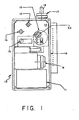
- the gas sampler 10 shown in Figure 1 includes a pump P, a DC motor M, a battery supply system 11, a flow control valve 12, a flow controller 14, a pressure switch 15, a damper 13, a mode selector valve 16 and a filter assembly 17, all of which are mounted in the case 18.
- the filter assembly 17 has an air intake boss 19 mounted on the outside of the case 18 and a filter membrane (not shown) to protect the gas sampler 10 from dirt and debris.
- the pump P may be a conventional single or dual piston diaphragm type pump such as is disclosed in applicant's earlier Patent No. US-A-4,432,248.
- the pump P is driven by the DC motor M which is powered by the battery supply system 11.
- the battery supply system 11 may consist of a nickel cadmium battery assembly and may further include a battery voltage indicator as well as a timer to indicate hours of operation.
- the speed of the drive motor M is proportional to the battery supply voltage.
- the flow envelope characteristic for the pump P is selected to provide the desired operating flow range for low flow air sampling.
- the vacuum pump P should typically provide a flow characteristic of 200 cc per minute at a minimum back pressure of 40 inches (1354.5 mbar) of water.
- a collecting device such as a sorbent tube for taking gas samples, preferably of air, is coupled to the inlet boss 19 of the gas sampler 10.
- a sorbent tube is a cylindrical shaped vial normally filled with a solid sorbent such as granulated charcoal and which is sealed at both ends with breakable end tips. The end tips are broken open when collecting an air sample.
- the pump P draws air through the sorbent tube at a fixed rate, preset by the manual adjustment of the flow control valve 12. The flow rate is monitored and regulated by the flow controller 14.
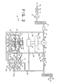
- Figure 2 is a schematic diagram of the gas sampler 10 of Figure 1 in the constant flow mode of operation.
- Figure 3 is a schematic diagram of the gas sampler of Figure 1 in the constant pressure mode of operation.
- the test article 20 represents the collecting device (sorbent tube) through which a flow of gas is drawn, preferably from the atmosphere, by the vacuum pump P, at a preset flow rate selected by adjustment of the flow control valve 12.
- the test article 20 is connected in series with the vacuum pump P and the flow control valve 12, with the test article 20 positioned on the suction side S of the pump P and with the flow control valve 12 positioned on the discharge side D of the pump P.
- An optional second filter 17A is interposed between the pump discharge D and the flow control valve preventing debris from affecting the setting of the flow control valve.
- the downstream end 25 of the flow control valve 12 is open to the atmosphere or is connected through an optional flow meter 26 to the atmosphere.
- the filter assembly 17 is connected on the downstream side 31 of the test article 20, upstream of the pump P.
- a damper 13 is coupled within the series flow path between the test article 20 and the pump P to further reduce pulse flow undulations.
- the operation of the filter 17 and damper 13 are independent of the pneumatic flow control system of the present invention.
- the flow meter 26 may be located in the series flow path between the test article 20 and the pump P, directly downstream of the filter assembly 17 instead of the location downstream of the flow control valve 12.
- the flow meter 26 may represent a vertically mounted conventional rotometer to indicate the preselected level of flow through the test article 20 over the operating range of typically between 2 to 200 cm 3 per minute in the constant flow mode and between 2 to 300 cm 3 per minute in the constant pressure operating mode.
- the flow rate specified are applicable to the low flow sampler described. However, the system can be scaled to operate at any flow rate.
- the manually adjustable flow control valve 12 is a conventional needle valve with an adjustable metering or flow control orifice 28 for establishing a predetermined restriction to flow in the series flow path including, in combination, the test article 20, the filter 17, the damper 13, the pump P, the filter 17A, and the flow control valve 12.
- the pump P draws air through the test article 20 at a fixed preset flow rate W1 as determined by the manual adjustment of the flow control valve 12.
- the flow rate W1 is regulated at the preset constant rate by the bypass flow controller 14.
- the bypass flow controller 14 is connected across the pump P to divert gas flow W2 from the discharge side D of the pump P and to reintroduce the diverted gas flow W2' into the suction side S of the pump P.
- the diverted gas fiow W2 passes through conduit 35 into the flow controller 14 and as regulated flow W2' through conduit 36 to a junction point 37 on the suction side S of the pump P at which point the flow W2' is added to the flow W1 to form a combined flow W3.
- the flow controller 14 is a miniature compact structure having an outer casing 40 with an internal cylindrical cavity 41 which is divided by a flexible diaphragm 42 into two plenum chambers 43 and 44, respectively.
- the flexible diaphragm 42 is of an elastomeric material having an annular rim held securely in place in an annular groove 44 formed in the outer casing 40.
- the diaphragm 42 constitutes a common wall for separating the cavity 41 into the two plenum chambers 43 and 44, respectively.
- a pair of plates 47 and 48 are mounted on opposite sides of the diaphragm 42.
- the plates 47 and 48 are preferably of a plastic composition and may be bonded to each opposite side of the diaphragm 42 or may have a tongue and groove configuration (not shown) so that they may be mechanically coupled to each other with the diaphragm 42 sandwiched between them.
- the bottom plate 48 has a depending pad 49 of elastomeric material which forms a valve piston head.
- the valve piston head 49 is aligned to register with a valve seat 50 formed as a rounded or dimpled protrusion upon a nozzle 51 projecting from the bottom wall 52 of the casing 40.
- the valve head 49 and valve seat 50 form a valve assembly.
- the valve head 49 has a flat surface 53 which engages the valve seat 50 when the valve head is urged into a closed position against the valve seat 50.
- the nozzle 51 has a central passageway 55 extending through the valve seat 50 and through the bottom wall 52 where it joins a conduit 56 leading into the return conduit 36.
- the flow controller 14 has a hollow boss 57 with a bore 58 coaxially aligned with the passageway 55 in the column 51.
- the bore 58 has a threaded counterbore 60 to receive a manually adjusting screw 62.
- a spring 64 is mounted with one end about a cylindrical post 65 extending from the screw 62 and with the opposite end seated in a recess in the plate 47. Adjustment of the screw 62 controls the compression of the spring 64 and in turn the loading force applied by the spring against the plate 47 and diaphragm 42.
- the chambers 43 and 44 of the flow controller 14 are pressurized to provide a pressure differential across the combination of the flow control valve 12 and the filter 17a.
- the lower chamber 44 is ported through an opening 70 to a conduit 71 which is coupled through conduit 35 to the discharge side of the pump P. Accordingly the pressure in the lower plenum chamber 44 is equal to the pressure on the discharge side D of the pump P, which, in this mode, is the same pressure as at the upstream end 74 of the combination of flow control valve 12 and filter 17A.
- the mode of operation of the gas sampler 10 is governed by the mode selector valve 16.
- the mode selector valve 16 as shown in more detail in Figure 4 includes a base 21 having multiple ports 72, 77, 76, 82, 24 and 81 and a manually adjustable rotor 100.
- the rotor 100 is mounted above the base 21 with the ports 72,77,76,82,24, and 81 sealed by O-ring glands 92 through 97.
- the rotor 100 is rotated from a first position as shown in Figure 2 defining the constant flow mode of operation to a second position as shown in Figure 3 defining the constant pressure mode of operation and vice versa.
- the second position requires a 180 degree rotation of the rotor 100 about its central axis. This is more clearly understood from the assembly drawing of Figure 4.
- the rotor 100 is fixed into an operating position only when the spring loaded balls 101 and 102 engage the rotor detents 105 and 106.
- the springs 103 and 104 are seated in recesses 109 and 110 in the base 21. In this position, the rotor 100 is sealed against the base 21 through the O-ring glands 92-97.
- the rotor 100 has internal tubulations 90 and 91 which in the position of Figure 2 interconnect port 72 to port 77 and port 76 to port 82. When the rotor is rotated 180 degrees about is central axis into the position shown in Figure 3, the internal tubulations 90 and 91 interconnect port 72 to port 81 and port 82 to port 24.
- the rotor detents 105 and 106 are configured with adjacent indented surfaces 111 and 112 which function as cams in conjunction with the detents to facilitate locking and unlocking of the rotor 100 with the base 21.
- Mode selection is achieved by rotation of the drive screw 107 which lifts the rotor 100 via the spring loaded balls 101 and 102 until the rotor jams against the lock nut 108. Additional turning of the screw 107 will now cause the rotor to deflect the balls into the housing and permit the rotor to rotate 180 degrees into the alternate position with the balls 101 and 102 engaging the detents 106 and 105 respectively. Reversing the screw direction will cause the detents 105 and 106 to prevent the rotor from rotating until the jam nut 108 disengages the rotor. Additional turning of the screw will cause the rotor to seal against the base by deflection of the O-rings 92 through 97.
- Port 81 in the mode selector valve 16 is coupled to the suction end of the pump through conducit 36 while port 24 is connected to the pump discharge through conduit 35 and to the lower chamber 44 of the flow controller 14.
- the ports 77 and 82 are connected in common to the discharge end of the flow control valve 12 through conduit 80.
- Port 72 is connected to chamber 43 of the flow controller 14 via conduit 75.
- ports 82 and 76 are connected through rotor tubulation 91 and ports 72 and 77 are connected via tubulation 90 thereby connecting chamber 43 to the discharge of the flow control valve 12.
- the supplementary flow W2 is diverted from the discharge end of the pump P and passed through the valve seat 50 into the suction end S of the pump P where it is combined as regulated supplementary flow W2' with the flow W1 such that the flow through the pump P is equal to W3.
- the valve assembly regulates the supplementary flow W2 in response to the summation of forces across the diaphragm 42 resulting in a displacement of the valve pad 49 from the valve seat 50 dictated by the equilibrium between the force applied by the preloaded spring 64 against the force of the differential pressure across the diaphragm and the force applied to the valve pad 49 through the valve seat 50 from the suction end S of the pump P.
- the equilibrium condition is satisfied when the pressure differential across the flow control valve 12 and, accordingly, between the upper and lower chambers 43 and 44, is restored to a preadjusted constant at the initially established operating condition based on the manual adjustment of the spring 64.
- the suction at the pump inlet end S of the pump P is dictated by whatever load the test article 20 may present over a wide range including any increased loading resulting from the filter assembly 17.
- the flow W1 through the test article 20 will be held constant at the pre-established value determined by adjustment of the flow control valve 12. Once the flow W1 is preset the flow controller 14 will maintain the flow W1 at the preset value independent of changes in load based either on a substitution of the test article 20 or resulting from an increased flow impedance due to dirt or debris in the filter assembly 17 or in the test article 20.
- the control variable is the supplementary flow W2 and the pressure differential across the flow control valve 12 is the regulated medium.
- the theory of opuration is based on regulating the pressure differential across the flow control valve 12 to a preselected constant and thereby maining a constant flow through the test article 20 in series therewith.
- the expression "maintaining a constant flow” is intended to mean regulated to a value having a close approximation to the initializing condition.
- the placement of the flow control valve 12 on the discharge side of the pump is such that the pressure on the downstream side 25 of the flow control valve 12 will be fixed, or essentially fixed, at atmospheric pressure. In this arrangement only one side of the flow control valve 12, viz., the discharge end of the pump P, requires regulation to maintain the differential pressure across the flow control valve constant.
- the pressure switch 15 is connected between the conduits 36 and 80 and operates in a conventional manner for the constant flow mode of operation to shut the pump P down by deenergizing the motor M should the total system pressure become higher than that for which the pump capacity is selected, thereby maintaining flow constant so long as the flow is maintained within prescribed limits.
- the pressure switch 15 may optionally be coupled through a conventional electronic time delay circuit 29 to provide a suitable time delay before deenergizing the motor M.
- the constant flow mode of operation is converted to a constant pressure mode of operation by rotating the mode select valve 16 180 degrees into the position of Figure 3.
- the port 24 is connected to the port 82 through rotor tubulation 90 thereby connecting the pump discharge via conduit 35 directly to the discharge of the flow control valve through conduit 80. This functionally removes filter 17A and the flow control valve 12 from the system.
- port 72 is connected to port 81 through rotor tubulation 91 thereby connecting the upper chamber 43 of the flow controller 14 to the suction side of the pump via conduit 36.
- the pressure in lower chamber 44 of the flow controller 14 remains equal to the pressure on the discharge side D of the pump which is now at atmospheric pressure or. is essentially at atmospheric pressure.
- the flow controller 14 will now be responsive to the pressure differential across the pump P which is equivalent to the pressure differential across the load since the flow control valve 12 is bypassed.
- the load for constant pressure operation is represented by a common manifold 190, to which a multiple number of test articles or sampling tubes 20 are connected, and by the filter and damper assemblies 17 and 13, respectively.
- the sampling tubes 20 are connected to the common manifold 190 through individually controller metering orifices 191, 192, and 193, respectively. Air is drawn by the pump P through the multiple sampling tubes 20 and through each of the respective metering orifices 91, 92, and 93 into the common manifold 190 from whence the air is drawn through the filter and damper assemblies 17 and 13, into the pump P.
- the flow controller 14 diverts flow W2 from the pump discharge back into the pump inlet to supplement the flow W1 from the common manifold 190 to maintain the pressure across the pump P at a preselected constant based upon adjustment of the screw 62. It should be clearly understood that in this mode of operation the flow W1 is flow stable but does not remain constant with changes in load.
- the pneumatic system arrangement in this mode of operation is similar to the fluid sampling disclosed in applicant's patent No. US-A-4,432,248.
Landscapes
- Engineering & Computer Science (AREA)
- Health & Medical Sciences (AREA)
- Physics & Mathematics (AREA)
- General Physics & Mathematics (AREA)
- Life Sciences & Earth Sciences (AREA)
- Molecular Biology (AREA)
- Automation & Control Theory (AREA)
- Biomedical Technology (AREA)
- Power Engineering (AREA)
- Chemical & Material Sciences (AREA)
- Analytical Chemistry (AREA)
- Biochemistry (AREA)
- General Health & Medical Sciences (AREA)
- Immunology (AREA)
- Pathology (AREA)
- Sampling And Sample Adjustment (AREA)
Description
- The invention relates to a pneumatic flow control system for collecting gas samples in a collecting device at a constant preselected flow rate.
- In the field of environmental hygiene, air sampling is performed regularly to test the air in industrial work environments to determine the degree of exposure to hazardous chemicals. A typical sampling method involves collecting a sample of a test gas such as air by drawing a known volume of the test gas through a collecting device such as a sorbent tube. The sorbent tube may include a solid sorbent capable of trapping and removing chemicals from the air or may include a filter for selectively collecting particulate. The test sample is then analyzed to determine the concentration level of the collected samples of chemical or particulate matter. The method of analysis may involve gas chromatography or atomic adsorption, etc. The analysis is based on a time weighted average over an eight hour work day to determine the concentration level of contaminants in parts per million. For the analysis to be accurate it is essential that sampling of test gas be performed at a constant fluid flow rate which is preselected for the chemical hazard under examination and the particular sorbent tube employed.
- Constant flow chemical sampling, i.e., sampling of gases or vapors through a single sample at a constant flow rate, is typically conducted at low flow levels in a flow range typically between 2 to 200 cm3 per minute depending upon the chemical hazard under analysis. In the sorbent tube sampling method, air is drawn through the sorbent tube by a vacuum pump at a flow rate which must be held constant in order to obtain a meaningful determination of the concentration level of the hazard under test. One currently used technique to assure constant flow is to use a pump and counter in conjunction with a precalibrated known volume of test gas from which the total volume can be derived. This technique is nonetheless susceptible to erroneous results from changes in load pressure, changes in pump volumetric efficiency, valve loading effects, etc. In another type of pump sampling system, air flow is controlled by adjustment of the pump motor speed. One conventional system uses a pressure switch to generate output pulses which vary in duration corresponding to variations in flow rate. The pulsed output is electronically sensed and converted to control signals having an amplitude which varies with pulse duration. The control signals are then used to adjust the pump motor speed. Another known motor speed control system disclosed in applicant's earlier "Hi-Flow" fluid sampling system, U.S. Patent No. 4,432, 248, utilizes load sensing of the pump motor to adjust motor speed in proportion to the pump load line curve. All known pump sampling systems which control flow by adjustment of pump motor speed produce an air flow with relatively high pulse undulations at the lower end of the flow regime. With a highly pulsed flow it is much more difficult if not impossible to set the flow rate. In fact at low flow rates of the order of 10 cm3 or below most common flow meters cannot be used to accurately determine or calibrate the flow because of their sensitivity to pulsation. Current state of the art technology requires several pumps to cover the flow range of 10 to 200 cm3/ min, therefore each pump is extremely limited in its range capability with the pulsation amplified at the lower end of its respective range.
- It is often desirable to take multiple test gas samples simultaneously without using a separate sampling pump for each sample. Multiple sampling involves the preparation of a multiple number of sorbent tubes, each of which is ported in series with individual variable restrictors dedicated to each tube station. The pressure across the manifold is maintained constant, thus allowing the flow rate through each sorbent tube to be individually determined by the setting of the individual restrictors in the manifold assembly. This arrangement allows independent control of the flow rates through each sorbent tube, provided that the total flow through all tubes does not exceed the constant pressure delivery capacity of the device.
- GB-A-2 037 426 from which the preamble of claim 1 has been derived discloses an apparatus for sampling a particle-bearing gas, which comprises a pump and a constant flow controller responsive to the static pressure of the gas in the stream downstream of the pump communicated to it via a duct. The flow controller provides a flow restriction upstream of the pump which gradually decreases to compensate for particles collecting on a filter located in the stream. The flow rate is set by a valve and timed by a programmer.
- US-A-3 251 377 discloses a hydraulic valve system which uses a pilot flow in a bypass line. The main flow passes through a pump and a flow controller and is throttled based on sensing a pilot flow variation. The valve is in the main flow path under the control of a secondary pilot flow.
- The problem underlying the present invention is to provide a pneumatic gas flow control system for regulating gas flow through a load at low gas flow rates so as to provide a flow stable system.
- This problem is solved by a pneumatic flow control system for collecting gas samples in a collecting device at a constant preselected flow rate comprising a vacuum pump, having a suction side and a discharge side, with said collecting device connected to the suction side of said pump,
- a flow control valve having a flow restricting orifice connected on the discharge side of said pump in series with said pump and said collecting device and a flow controller having in- and output openings and valve means, which are responsive to the pressure at the discharge side of the pump so as to maintain the flow of gas flowing through the collecting device constant at said preselected flow rate independent of load variations, which is characterized in that:
- a supplementary flow of gas is diverted from the total flow of gas at the discharge side of the pump and fed into the input opening of the flow- controller for regulating said supplementary flow of gas and in that the regulated supplementary flow of gas at the output-opening of the flow controller is combined with the flow of gas to the total flow of gas which flows into the suction side of the pump.
- In a preferred embodiment said flow control valve is manually adjustable for varying the size of said flow restricting orifice in order to preset said flow rate through said collecting device.
- Preferably, said flow controller further comprises a hollow casing, a flexible diaphragm assembly separating the hollow casing into a first and second plenum chamber, means for coupling said first plenum chamberto the flow control valve on the discharge side of the pump, means for coupling said second plenum chamber to the opposite side of said flow control valve such that it is at substantially atmospheric pressure, spring means extending into said second plenum chamber in engagement with said diaphragm for applying a predetermined spring force, said valve means being responsive to the pressure differential between said first and second plenum chamber and to said spring force for regulating said supplementary flow of gas through said first plenum chamber into the suction side of said pump;
- said spring means preferably are adjustable for varying said spring force upon said diaphragm;
- said valve means preferably comprise a valve pad extending from said diaphragm and a hollow valve seat disposed in said first plenum chamber in registration with said valve pad;
- said valve pad preferably has a flat surface engaging said valve seat in the closed valve position, and
- said valve seat preferably has a dimpled annular protrusion for engaging the flat surface of said valve pad in the closed valve position.
- A further aspect of the invention relates to a pneumatic control system for devices for collecting gas samples in a load represented either by a single test article or a multiple number of test articles connected in series with individual variable restrictors dedicated to each test article, having a vacuum pump including a suction side and a discharge side, this system being characterized in that it comprises a mode select valve for converting the control system from a constant flow control to a constant pressure control, whereby in a first position of the mode select valve the flow controller is coupled across the pump so that the valve means regulate the supplementary flow in response to the pressure differential across said flow control valve to provide a constant gas flow through said load represented by a single test article and in a second positon of the mode select valve the flow control valve is bypassed and the flow controller is connected across the pump such that the valve means regulate said supplementary flow in response to the pressure differential across the pump to provide a constant pressure across the load represented by a multiple number of test articles.
- Preferably said flow controllerfurthercomprises a hollow casing and a diaphragm assembly separating the casing into a first and second plenum chamber, spring means extending into said second plenum chamber in engagement with said diaphragm assembly and conduit means for coupling said first and second plenum chambers to said mode select valve,
- said valve means preferably comprising a valve pad extending from said diaphragm and a hollow valve seat disposed in said first plenum chamber in registration with said valve pad and coupled to the suction side of the pump for regulating the supplementary flow from the first plenum chamber into the valve seat; and
- further when said mode select valve is in said first position said second plenum chamber preferably is connected through said mode select valve to the downstream side of said flow control valve at substantially atmospheric pressure and said first plenum chamber is connected to the flow control valve at the discharge side of said pump.
- Said load is preferably a single test article and the flow therethrough is regulated at a preselected flow rate based upon the size of said flow restricting orifice.
- When said mode select valve is in the second position said second plenum chamber is connected through said mode select valve to the suction side of said pump and said first plenum chamber is connected to the flow control valve at the discharge side of the pump as well as through said mode select valve to the downstream side of said flow control valve.
- Preferably said load is a multiple number of test articles connected to a common manifold with the pressure across said manifold being constant.
- Said mode select valve preferably comprises a base having a multiple number of ports and a manually rotatable rotor having internal tubulations which in one position of the rotor interconnect a first predetermined set of said ports to couple said flow controller across said flow control valve and in another position interconnect a second predetermined set of ports to bypass said flow control valve.
- Preferably said mode select valve further comprises detents in said rotor and spring loaded balls arranged in said base to provide controlled rotation between said two positions.
- The use of the control system according to the present invention allows a gas sampler which has a dual mode capability permitting the user to readily switch from a constant flow single sample mode of operation to a constant pressure multiple sample mode of operation.
- The flow through a test article connected in series with a vacuum pump and a metering orifice may be held at a constant preselected flow by maintaining a regulated pressure differential across the flow metering orifice. This is accomplished by the controlled addition of a secondary gas stream to supplement the metered gas flow stream drawn by the pump through the test article. The secondary gas stream is regulated by a flow controller connected across the pump and connected to respond to the pressure differential across the metering orifice. The flow controller operates to divert a controlled fraction of the pump total flow from the net pump discharge and to reintroduce it at the pump inlet in combination with the metered mass flow to maintain the mass flow constant. The flow controller can include a ganged dual diaphragm assembly forming two diaphragm chambers separated by a central plenum chamber with each diaphragm chamber ported through a separate conduit to one side of the metering orifice, a valve assembly responsive to the difference in pressure in each of the diaphragm chambers for controlling the secondary stream and a preloaded spring for adjusting the initial equilibrium condition. The flow controller can be placed on the suction or discharge side of the vacuum pump in a series arrangement with the test article and the pump. It has been found in accordance with the present invention that a single diaphragm flow controller may be used to provide the equivalent function of the more complex dual diaphragm controller not only for constant flow sampling but also for multiple draw sampling provided that the metering orifice is located on the discharge end of the pump in a series arrangement with the test article and the pump, and that one end of the metering orifice is tied, substantially, to atmospheric pressure. The pressure differential across the metering orifice is then regulated for the purpose of maintaining a constant mass flow through the test article. The suction at the pump inlet is dictated by whatever load or changing load the test article may present, over a wide range bounded by the intrinsic limits of regulation provided by a given sampler specification or design. The flow controller regulates the supply of secondary gas flow to assure a constant primary mass flow independent of variations in the test article load and at any preselected primary gas flow level of a wide range. Moreover, flow is controlled substantially independent of the pump operating speed and charcteristics.
- Furthermore, in the constant flow mode of operation the system will automatically compensate for any change in test load to assure a constant flow rate without requiring recalibration each time a new test sorbent tube is introduced into the system. The flow rate is established by adjustment of the metering orifice to a desired flow setting over a wide flow range.
- The flow controller in the present application is a miniature structure having a cylindrical cavity with a single flexible diaphragm disposed in the cavity to constitute a common wall for dividing the cavity into a first and second plenum chamber and also includes a preloaded manually adjustable spring extending into one of the chambers in engagement with the diaphragm. The flow controller further includes a valve assembly having a valve head connected to the diaphragm with which it moves freely as one unit to assume a valve displacement dictated by the equilibrium of the preloaded spring acting against the force of . the differential pressure across the diaphragm.
- In the constant flow mode of operation the flow controller responds to the pressure difference across the flow control valve to regulate the secondary supply of gas to maintain the mass flow through the collecting device constant independent of load variations.
- The mode selector valve provides for two operating modes, constant flow and constant pressure. In the constant flow mode a single test article is sampled and the system will maintain the flow constant regardless of pressure changes in the test article. In the constant pressure mode the mode selector valve bypasses the flow control valve to reduce the gas sample to a series arrangement between the pump and collecting device preferably represented for this operation by a common manifold and a multiple number of test articles. The flow controller remains connected across the pump to divert flow from the pump discharges to the pump inlet and is connected, in this mode of operation, through the mode selector valve to respond to the pressure differential across the pump. This arrangement for constant pressure sampling is substantially similar to the regulator and pump arrangement shown and described in applicant's earlier U.S. Patent No. 4,432,248 entitled Fluid Sampling. The mode selector valve is in itself unique in that it provides for switching the interconnections between the flow control valve, the flow controller and the pump to convert from a constant flow mode of operation to a constant pressure mode of operation and vice versa by means of a single manual rotation of the selector valve rotor. The selector valve is also of miniature size permitting the entire gas sampling system to be housed in a compact miniature case.
-
- Figure 1 is a full scale side elevation of the gas sampler and pneumatic flow control system of the present invention;
- Figure 2 is a system schematic diagram of the gas sampler of Figure 1 showing the pneumatic flow control system of the present invention in the constant flow mode of operation;
- Figure 3 is a system schematic diagram similar to Figure 2 showing the pneumatic flow control system in the constant pressure mode of operation; and
- Figure 4 is an exploded view in isometric of the mode selector valve of Figures 2 and 3.
- The
gas sampler 10 shown in Figure 1 includes a pump P, a DC motor M, a battery supply system 11, aflow control valve 12, aflow controller 14, apressure switch 15, adamper 13, amode selector valve 16 and afilter assembly 17, all of which are mounted in thecase 18. Thefilter assembly 17 has anair intake boss 19 mounted on the outside of thecase 18 and a filter membrane (not shown) to protect thegas sampler 10 from dirt and debris. The pump P may be a conventional single or dual piston diaphragm type pump such as is disclosed in applicant's earlier Patent No. US-A-4,432,248. The pump P is driven by the DC motor M which is powered by the battery supply system 11. The battery supply system 11 may consist of a nickel cadmium battery assembly and may further include a battery voltage indicator as well as a timer to indicate hours of operation. The speed of the drive motor M is proportional to the battery supply voltage. The flow envelope characteristic for the pump P is selected to provide the desired operating flow range for low flow air sampling. The vacuum pump P should typically provide a flow characteristic of 200 cc per minute at a minimum back pressure of 40 inches (1354.5 mbar) of water. - A collecting device such as a sorbent tube for taking gas samples, preferably of air, is coupled to the
inlet boss 19 of thegas sampler 10. A sorbent tube is a cylindrical shaped vial normally filled with a solid sorbent such as granulated charcoal and which is sealed at both ends with breakable end tips. The end tips are broken open when collecting an air sample. The pump P draws air through the sorbent tube at a fixed rate, preset by the manual adjustment of theflow control valve 12. The flow rate is monitored and regulated by theflow controller 14. - Operation of the
gas sampler 10 will now be described in connection with Figures 2, 3 and 4 wherein like reference numerals are used to designate the corresponding components. Figure 2 is a schematic diagram of thegas sampler 10 of Figure 1 in the constant flow mode of operation. Likewise, Figure 3 is a schematic diagram of the gas sampler of Figure 1 in the constant pressure mode of operation. - The
test article 20 represents the collecting device (sorbent tube) through which a flow of gas is drawn, preferably from the atmosphere, by the vacuum pump P, at a preset flow rate selected by adjustment of theflow control valve 12. Thetest article 20 is connected in series with the vacuum pump P and theflow control valve 12, with thetest article 20 positioned on the suction side S of the pump P and with theflow control valve 12 positioned on the discharge side D of the pump P. An optionalsecond filter 17A is interposed between the pump discharge D and the flow control valve preventing debris from affecting the setting of the flow control valve. Thedownstream end 25 of theflow control valve 12 is open to the atmosphere or is connected through anoptional flow meter 26 to the atmosphere. - The
filter assembly 17 is connected on thedownstream side 31 of thetest article 20, upstream of the pump P. Adamper 13 is coupled within the series flow path between thetest article 20 and the pump P to further reduce pulse flow undulations. The operation of thefilter 17 anddamper 13 are independent of the pneumatic flow control system of the present invention. Theflow meter 26 may be located in the series flow path between thetest article 20 and the pump P, directly downstream of thefilter assembly 17 instead of the location downstream of theflow control valve 12. Theflow meter 26 may represent a vertically mounted conventional rotometer to indicate the preselected level of flow through thetest article 20 over the operating range of typically between 2 to 200 cm3 per minute in the constant flow mode and between 2 to 300 cm3 per minute in the constant pressure operating mode. The flow rate specified are applicable to the low flow sampler described. However, the system can be scaled to operate at any flow rate. - The manually adjustable
flow control valve 12 is a conventional needle valve with an adjustable metering or flowcontrol orifice 28 for establishing a predetermined restriction to flow in the series flow path including, in combination, thetest article 20, thefilter 17, thedamper 13, the pump P, thefilter 17A, and theflow control valve 12. The pump P draws air through thetest article 20 at a fixed preset flow rate W1 as determined by the manual adjustment of theflow control valve 12. - The flow rate W1 is regulated at the preset constant rate by the
bypass flow controller 14. Thebypass flow controller 14 is connected across the pump P to divert gas flow W2 from the discharge side D of the pump P and to reintroduce the diverted gas flow W2' into the suction side S of the pump P. The diverted gas fiow W2 passes throughconduit 35 into theflow controller 14 and as regulated flow W2' throughconduit 36 to ajunction point 37 on the suction side S of the pump P at which point the flow W2' is added to the flow W1 to form a combined flow W3. - The
flow controller 14 is a miniature compact structure having anouter casing 40 with an internalcylindrical cavity 41 which is divided by aflexible diaphragm 42 into twoplenum chambers flexible diaphragm 42 is of an elastomeric material having an annular rim held securely in place in anannular groove 44 formed in theouter casing 40. Thediaphragm 42 constitutes a common wall for separating thecavity 41 into the twoplenum chambers - A pair of
plates diaphragm 42. Theplates diaphragm 42 or may have a tongue and groove configuration (not shown) so that they may be mechanically coupled to each other with thediaphragm 42 sandwiched between them. Thebottom plate 48 has a dependingpad 49 of elastomeric material which forms a valve piston head. Thevalve piston head 49 is aligned to register with avalve seat 50 formed as a rounded or dimpled protrusion upon anozzle 51 projecting from thebottom wall 52 of thecasing 40. Thevalve head 49 andvalve seat 50 form a valve assembly. Thevalve head 49 has aflat surface 53 which engages thevalve seat 50 when the valve head is urged into a closed position against thevalve seat 50. Thenozzle 51 has acentral passageway 55 extending through thevalve seat 50 and through thebottom wall 52 where it joins aconduit 56 leading into thereturn conduit 36. - The
flow controller 14 has ahollow boss 57 with abore 58 coaxially aligned with thepassageway 55 in thecolumn 51. Thebore 58 has a threadedcounterbore 60 to receive a manually adjustingscrew 62. Aspring 64 is mounted with one end about acylindrical post 65 extending from thescrew 62 and with the opposite end seated in a recess in theplate 47. Adjustment of thescrew 62 controls the compression of thespring 64 and in turn the loading force applied by the spring against theplate 47 anddiaphragm 42. - The
chambers flow controller 14 are pressurized to provide a pressure differential across the combination of theflow control valve 12 and the filter 17a. Thelower chamber 44 is ported through an opening 70 to aconduit 71 which is coupled throughconduit 35 to the discharge side of the pump P. Accordingly the pressure in thelower plenum chamber 44 is equal to the pressure on the discharge side D of the pump P, which, in this mode, is the same pressure as at theupstream end 74 of the combination offlow control valve 12 andfilter 17A. - The mode of operation of the
gas sampler 10 is governed by themode selector valve 16. Themode selector valve 16 as shown in more detail in Figure 4 includes a base 21 havingmultiple ports adjustable rotor 100. Therotor 100 is mounted above the base 21 with theports ring glands 92 through 97. Therotor 100 is rotated from a first position as shown in Figure 2 defining the constant flow mode of operation to a second position as shown in Figure 3 defining the constant pressure mode of operation and vice versa. The second position requires a 180 degree rotation of therotor 100 about its central axis. This is more clearly understood from the assembly drawing of Figure 4. Therotor 100 is fixed into an operating position only when the spring loadedballs rotor detents springs recesses base 21. In this position, therotor 100 is sealed against the base 21 through the O-ring glands 92-97. Therotor 100 has internal tubulations 90 and 91 which in the position of Figure 2interconnect port 72 toport 77 andport 76 toport 82. When the rotor is rotated 180 degrees about is central axis into the position shown in Figure 3, the internal tubulations 90 and 91interconnect port 72 toport 81 andport 82 toport 24. - The
rotor detents indented surfaces 111 and 112 which function as cams in conjunction with the detents to facilitate locking and unlocking of therotor 100 with thebase 21. - Mode selection is achieved by rotation of the
drive screw 107 which lifts therotor 100 via the spring loadedballs lock nut 108. Additional turning of thescrew 107 will now cause the rotor to deflect the balls into the housing and permit the rotor to rotate 180 degrees into the alternate position with theballs detents detents jam nut 108 disengages the rotor. Additional turning of the screw will cause the rotor to seal against the base by deflection of the O-rings 92 through 97. -
Port 81 in themode selector valve 16 is coupled to the suction end of the pump throughconducit 36 whileport 24 is connected to the pump discharge throughconduit 35 and to thelower chamber 44 of theflow controller 14. Theports flow control valve 12 throughconduit 80.Port 72 is connected tochamber 43 of theflow controller 14 viaconduit 75. - In the constant flow mode of operation,
ports rotor tubulation 91 andports tubulation 90 thereby connectingchamber 43 to the discharge of theflow control valve 12. The supplementary flow W2 is diverted from the discharge end of the pump P and passed through thevalve seat 50 into the suction end S of the pump P where it is combined as regulated supplementary flow W2' with the flow W1 such that the flow through the pump P is equal to W3. The valve assembly regulates the supplementary flow W2 in response to the summation of forces across thediaphragm 42 resulting in a displacement of thevalve pad 49 from thevalve seat 50 dictated by the equilibrium between the force applied by thepreloaded spring 64 against the force of the differential pressure across the diaphragm and the force applied to thevalve pad 49 through thevalve seat 50 from the suction end S of the pump P. The equilibrium condition is satisfied when the pressure differential across theflow control valve 12 and, accordingly, between the upper andlower chambers spring 64. The suction at the pump inlet end S of the pump P is dictated by whatever load thetest article 20 may present over a wide range including any increased loading resulting from thefilter assembly 17. - The flow W1 through the
test article 20 will be held constant at the pre-established value determined by adjustment of theflow control valve 12. Once the flow W1 is preset theflow controller 14 will maintain the flow W1 at the preset value independent of changes in load based either on a substitution of thetest article 20 or resulting from an increased flow impedance due to dirt or debris in thefilter assembly 17 or in thetest article 20. The control variable is the supplementary flow W2 and the pressure differential across theflow control valve 12 is the regulated medium. - The theory of opuration is based on regulating the pressure differential across the
flow control valve 12 to a preselected constant and thereby maining a constant flow through thetest article 20 in series therewith. The expression "maintaining a constant flow" is intended to mean regulated to a value having a close approximation to the initializing condition. The placement of theflow control valve 12 on the discharge side of the pump is such that the pressure on thedownstream side 25 of theflow control valve 12 will be fixed, or essentially fixed, at atmospheric pressure. In this arrangement only one side of theflow control valve 12, viz., the discharge end of the pump P, requires regulation to maintain the differential pressure across the flow control valve constant. - The
pressure switch 15 is connected between theconduits pressure switch 15 may optionally be coupled through a conventional electronictime delay circuit 29 to provide a suitable time delay before deenergizing the motor M. - The constant flow mode of operation is converted to a constant pressure mode of operation by rotating the mode
select valve 16 180 degrees into the position of Figure 3. In the constant pressure mode, theport 24 is connected to theport 82 throughrotor tubulation 90 thereby connecting the pump discharge viaconduit 35 directly to the discharge of the flow control valve throughconduit 80. This functionally removesfilter 17A and theflow control valve 12 from the system. Inaddition port 72 is connected to port 81 throughrotor tubulation 91 thereby connecting theupper chamber 43 of theflow controller 14 to the suction side of the pump viaconduit 36. The pressure inlower chamber 44 of theflow controller 14 remains equal to the pressure on the discharge side D of the pump which is now at atmospheric pressure or. is essentially at atmospheric pressure. Theflow controller 14 will now be responsive to the pressure differential across the pump P which is equivalent to the pressure differential across the load since theflow control valve 12 is bypassed. The load for constant pressure operation is represented by acommon manifold 190, to which a multiple number of test articles orsampling tubes 20 are connected, and by the filter anddamper assemblies sampling tubes 20 are connected to thecommon manifold 190 through individuallycontroller metering orifices multiple sampling tubes 20 and through each of therespective metering orifices common manifold 190 from whence the air is drawn through the filter anddamper assemblies flow controller 14 diverts flow W2 from the pump discharge back into the pump inlet to supplement the flow W1 from thecommon manifold 190 to maintain the pressure across the pump P at a preselected constant based upon adjustment of thescrew 62. It should be clearly understood that in this mode of operation the flow W1 is flow stable but does not remain constant with changes in load. The pneumatic system arrangement in this mode of operation is similar to the fluid sampling disclosed in applicant's patent No. US-A-4,432,248.
Claims (9)
Priority Applications (1)
| Application Number | Priority Date | Filing Date | Title |
|---|---|---|---|
| AT84108026T ATE58243T1 (en) | 1983-07-12 | 1984-07-09 | GAS SAMPLING DEVICE WITH TWO MODES OF OPERATION AND PNEUMATIC FLOW CONTROL SYSTEM. |
Applications Claiming Priority (4)
| Application Number | Priority Date | Filing Date | Title |
|---|---|---|---|
| US06/512,935 US4532814A (en) | 1983-07-12 | 1983-07-12 | Fluid sampler and gas flow control system and method |
| US512935 | 1983-07-12 | ||
| US612334 | 1984-05-21 | ||
| US06/612,334 US4576054A (en) | 1983-07-12 | 1984-05-21 | Dual mode gas sampler and pneumatic flow control system |
Publications (3)
| Publication Number | Publication Date |
|---|---|
| EP0134989A2 EP0134989A2 (en) | 1985-03-27 |
| EP0134989A3 EP0134989A3 (en) | 1986-03-12 |
| EP0134989B1 true EP0134989B1 (en) | 1990-11-07 |
Family
ID=27057709
Family Applications (1)
| Application Number | Title | Priority Date | Filing Date |
|---|---|---|---|
| EP84108026A Expired EP0134989B1 (en) | 1983-07-12 | 1984-07-09 | Dual mode gas sampler and pneumatic flow control system |
Country Status (4)
| Country | Link |
|---|---|
| US (1) | US4576054A (en) |
| EP (1) | EP0134989B1 (en) |
| CA (1) | CA1226508A (en) |
| DE (1) | DE3483550D1 (en) |
Families Citing this family (25)
| Publication number | Priority date | Publication date | Assignee | Title |
|---|---|---|---|---|
| US4889692A (en) * | 1984-11-05 | 1989-12-26 | Holtzman Marc E | Disposable sample preparation container |
| US4896548A (en) * | 1988-12-27 | 1990-01-30 | Gilian Instrument Corp. | Fluid sampler with miniature single-acting pump assembly |
| JP2535425B2 (en) | 1989-12-26 | 1996-09-18 | ギリアン インストルメント コーポレーション | Fluid sampler with single action pump assembly |
| US5163818A (en) * | 1990-02-05 | 1992-11-17 | Ametek, Inc. | Automatic constant air flow rate pump unit for sampling air |
| US5101671A (en) * | 1990-10-01 | 1992-04-07 | Elgas David H | Compressed gas sampling device |
| US5235190A (en) * | 1991-01-29 | 1993-08-10 | Gemini Research, Inc. | Continuous air monitoring system |
| US5199853A (en) * | 1991-02-26 | 1993-04-06 | Padden Harvey F | Pneumatic flow control system |
| US5571948A (en) * | 1995-05-22 | 1996-11-05 | Lawrence Factor, Inc. | Pressurized air tank air quality tester |
| US6146591A (en) * | 1998-05-01 | 2000-11-14 | Miller; C David | Biochemical detection system for rapid determination of the presence of toxins, bacteria, and other substances |
| US5892160A (en) * | 1998-05-08 | 1999-04-06 | Skc, Inc. | Isothermal flow controller for air sampler |
| FR2779824B1 (en) * | 1998-06-15 | 2000-07-21 | Air Liquide | ATMOSPHERE ANALYSIS INSTALLATION |
| DE19860639A1 (en) * | 1998-12-29 | 2000-07-06 | Man Turbomasch Ag Ghh Borsig | Method for operating a compressor with a downstream consumer, and system operating according to the method |
| US6477906B1 (en) * | 1999-03-02 | 2002-11-12 | Roger Peterson Family Limited | Automatic multi-sorbent tube air sampler |
| US6584865B1 (en) * | 2001-03-08 | 2003-07-01 | The United States Of America As Represented By The Secretary Of The Army | Absolute reference aerosol sampler |
| US7140232B2 (en) * | 2002-12-16 | 2006-11-28 | Radiodetection Limited | Method and apparatus for multiple gas sensor |
| US9164111B2 (en) * | 2007-03-12 | 2015-10-20 | Resolved Technologies, Inc. | Device for multiple tests from a single sample |
| EP2972127B1 (en) * | 2013-03-12 | 2019-12-18 | Illinois Tool Works Inc. | Turning vane |
| US9182320B2 (en) * | 2013-03-15 | 2015-11-10 | The United States Of America, As Represented By The Secretary Of The Navy | System apparatus and method of sampling a broad range of chemicals (SBRC) by collection and analysis of chemical vapors aerosols particulates and liquid droplets on surfaces |
| CN104502162B (en) * | 2014-12-31 | 2017-07-07 | 郑州光力科技股份有限公司 | Dust sampler and the dust concentration caliberating device using the dust sampler |
| US10001115B2 (en) * | 2015-04-16 | 2018-06-19 | Ideal Industries, Inc. | Air sampler with closed loop flow control system |
| CN109357920B (en) * | 2018-11-15 | 2024-03-22 | 深圳国技仪器有限公司 | Portable wide-range ambient air sampler |
| US11268886B2 (en) * | 2019-06-27 | 2022-03-08 | The Procter & Gamble Company | Portable automatic air sampling device and method of collecting air samples therefrom |
| JP6954336B2 (en) * | 2019-10-08 | 2021-10-27 | 栗田工業株式会社 | Water sampling device for water quality measurement |
| CN113640073B (en) * | 2021-08-12 | 2024-06-07 | 北京纳颗环境科技有限公司 | Multichannel micro-flow sampling controller |
| CN115508158B (en) * | 2022-11-02 | 2024-02-06 | 江苏华创检测技术服务有限公司科技研发中心 | Portable malodorous gas rapid sampler |
Family Cites Families (17)
| Publication number | Priority date | Publication date | Assignee | Title |
|---|---|---|---|---|
| US1873010A (en) * | 1928-01-17 | 1932-08-23 | Borden Co | Apparatus for taking samples of milk |
| US2976885A (en) * | 1955-07-08 | 1961-03-28 | Orr & Sembower Inc | Fuel control valves |
| US2819774A (en) * | 1956-06-04 | 1958-01-14 | Alfred C Schmidt | Constant flow suction unit |
| FR1236631A (en) * | 1959-06-11 | 1960-07-22 | Device ensuring a low permanent fluid flow | |
| GB1023879A (en) * | 1962-12-18 | 1966-03-30 | Alfa Laval Ab | Valve and flow controller provided with said valve |
| US3343217A (en) * | 1964-07-08 | 1967-09-26 | Daco Rubber Inc | Press molding apparatus |
| US3447360A (en) * | 1965-07-26 | 1969-06-03 | Independent Exploration Co Of | Method of and apparatus for exploring for deposits of helium and detection of helium in gaseous mixtures |
| US3543784A (en) * | 1967-10-13 | 1970-12-01 | Phillips Petroleum Co | Flow control system |
| US3751983A (en) * | 1972-03-23 | 1973-08-14 | Pro Tech Inc | Liquid sampling |
| US3965747A (en) * | 1972-10-24 | 1976-06-29 | Joy Manufacturing Company | Gas sampling system and method |
| US4246788A (en) * | 1978-11-30 | 1981-01-27 | Sierra Instruments, Inc. | Method and apparatus for sampling of a particle-bearing gas |
| US4269059A (en) * | 1979-03-19 | 1981-05-26 | E. I. Du Pont De Nemours And Company | Dosimeter having constant flow pump |
| GB2053155A (en) * | 1979-07-09 | 1981-02-04 | Exxon Research Engineering Co | Sampling device for isokinetic sampling |
| US4288206A (en) * | 1979-08-15 | 1981-09-08 | Tigwell David C | Automatic multiple water sampler |
| EP0040928B1 (en) * | 1980-05-14 | 1984-09-19 | ROTHEROE & MITCHELL LIMITED | Gas sampler |
| US4432248A (en) * | 1980-10-29 | 1984-02-21 | Gilian Instrument Corporation | Fluid sampling |
| FR2498755A1 (en) * | 1981-01-27 | 1982-07-30 | Ams Sa | PROTECTIVE APPARATUS FOR DIFFERENTIAL PRESSURE SENSORS AGAINST EXCEEDING MAXIMUM DIFFERENTIAL PRESSURE DATA |
-
1984
- 1984-05-21 US US06/612,334 patent/US4576054A/en not_active Expired - Lifetime
- 1984-07-09 DE DE8484108026T patent/DE3483550D1/en not_active Expired - Fee Related
- 1984-07-09 EP EP84108026A patent/EP0134989B1/en not_active Expired
- 1984-07-11 CA CA000458583A patent/CA1226508A/en not_active Expired
Also Published As
| Publication number | Publication date |
|---|---|
| EP0134989A2 (en) | 1985-03-27 |
| EP0134989A3 (en) | 1986-03-12 |
| US4576054A (en) | 1986-03-18 |
| CA1226508A (en) | 1987-09-08 |
| DE3483550D1 (en) | 1990-12-13 |
Similar Documents
| Publication | Publication Date | Title |
|---|---|---|
| US4576054A (en) | Dual mode gas sampler and pneumatic flow control system | |
| US4532814A (en) | Fluid sampler and gas flow control system and method | |
| US4246788A (en) | Method and apparatus for sampling of a particle-bearing gas | |
| US5006227A (en) | Volumetric flow controller for aerosol classifier | |
| EP0604020B1 (en) | Flow-controlled sampling pump apparatus | |
| US6422256B1 (en) | Fluid flow controlling | |
| US5317930A (en) | Constant flowrate controller for an aerosol sampler using a filter | |
| US3416547A (en) | Separating flow control system and method | |
| US3534753A (en) | Ratio controller for gases | |
| JPS6250762B2 (en) | ||
| US4542740A (en) | Gas dosing device for medical apparatus | |
| US4432248A (en) | Fluid sampling | |
| US2982131A (en) | Automatic isokinetic sampling device | |
| US3653399A (en) | Gas flow controlling system | |
| US3859842A (en) | System for determining the dust content of gases | |
| EP0973080B1 (en) | Gas flow rate control apparatus | |
| EP0376247B1 (en) | Fluid sampler with miniature single-acting pump assembly | |
| RU97117964A (en) | INSTALLATION FOR MEASURING WELL DEBIT | |
| US4254789A (en) | Apparatus for mixing media, such as gases or liquids | |
| CA1296547C (en) | Fluidic oxygen sensor monitor | |
| US20050229976A1 (en) | Adjustable rinse flow in semiconductor processing | |
| JP2003050194A (en) | Gas dilution system | |
| JPS59117614A (en) | Constant flow rate governor | |
| JPH0694502A (en) | Flowmeter | |
| Lee et al. | Design and performance evaluation of a pressure-reducing device for aerosol sampling from high-purity gases |
Legal Events
| Date | Code | Title | Description |
|---|---|---|---|
| PUAI | Public reference made under article 153(3) epc to a published international application that has entered the european phase |
Free format text: ORIGINAL CODE: 0009012 |
|
| AK | Designated contracting states |
Designated state(s): AT BE CH DE FR GB IT LI LU NL SE |
|
| PUAL | Search report despatched |
Free format text: ORIGINAL CODE: 0009013 |
|
| AK | Designated contracting states |
Kind code of ref document: A3 Designated state(s): AT BE CH DE FR GB IT LI LU NL SE |
|
| 17P | Request for examination filed |
Effective date: 19860911 |
|
| 17Q | First examination report despatched |
Effective date: 19880304 |
|
| GRAA | (expected) grant |
Free format text: ORIGINAL CODE: 0009210 |
|
| AK | Designated contracting states |
Kind code of ref document: B1 Designated state(s): AT BE CH DE FR GB IT LI LU NL SE |
|
| PG25 | Lapsed in a contracting state [announced via postgrant information from national office to epo] |
Ref country code: SE Effective date: 19901107 Ref country code: LI Effective date: 19901107 Ref country code: CH Effective date: 19901107 Ref country code: BE Effective date: 19901107 Ref country code: AT Effective date: 19901107 |
|
| REF | Corresponds to: |
Ref document number: 58243 Country of ref document: AT Date of ref document: 19901115 Kind code of ref document: T |
|
| REF | Corresponds to: |
Ref document number: 3483550 Country of ref document: DE Date of ref document: 19901213 |
|
| ET | Fr: translation filed | ||
| ITF | It: translation for a ep patent filed | ||
| REG | Reference to a national code |
Ref country code: CH Ref legal event code: PL |
|
| ITTA | It: last paid annual fee | ||
| PG25 | Lapsed in a contracting state [announced via postgrant information from national office to epo] |
Ref country code: LU Free format text: LAPSE BECAUSE OF NON-PAYMENT OF DUE FEES Effective date: 19910731 |
|
| PGFP | Annual fee paid to national office [announced via postgrant information from national office to epo] |
Ref country code: NL Payment date: 19910731 Year of fee payment: 8 |
|
| PLBE | No opposition filed within time limit |
Free format text: ORIGINAL CODE: 0009261 |
|
| STAA | Information on the status of an ep patent application or granted ep patent |
Free format text: STATUS: NO OPPOSITION FILED WITHIN TIME LIMIT |
|
| 26N | No opposition filed | ||
| PG25 | Lapsed in a contracting state [announced via postgrant information from national office to epo] |
Ref country code: NL Effective date: 19930201 |
|
| NLV4 | Nl: lapsed or anulled due to non-payment of the annual fee | ||
| PGFP | Annual fee paid to national office [announced via postgrant information from national office to epo] |
Ref country code: GB Payment date: 19970709 Year of fee payment: 14 |
|
| PGFP | Annual fee paid to national office [announced via postgrant information from national office to epo] |
Ref country code: FR Payment date: 19970730 Year of fee payment: 14 |
|
| PGFP | Annual fee paid to national office [announced via postgrant information from national office to epo] |
Ref country code: DE Payment date: 19970925 Year of fee payment: 14 |
|
| PG25 | Lapsed in a contracting state [announced via postgrant information from national office to epo] |
Ref country code: GB Free format text: LAPSE BECAUSE OF NON-PAYMENT OF DUE FEES Effective date: 19980709 |
|
| GBPC | Gb: european patent ceased through non-payment of renewal fee |
Effective date: 19980709 |
|
| PG25 | Lapsed in a contracting state [announced via postgrant information from national office to epo] |
Ref country code: FR Free format text: LAPSE BECAUSE OF NON-PAYMENT OF DUE FEES Effective date: 19990331 |
|
| PG25 | Lapsed in a contracting state [announced via postgrant information from national office to epo] |
Ref country code: DE Free format text: LAPSE BECAUSE OF NON-PAYMENT OF DUE FEES Effective date: 19990501 |
|
| REG | Reference to a national code |
Ref country code: FR Ref legal event code: ST |