EP0134273B1 - Pulse light stabilization for color spectrophotometric instrumentation - Google Patents
Pulse light stabilization for color spectrophotometric instrumentation Download PDFInfo
- Publication number
- EP0134273B1 EP0134273B1 EP83108329A EP83108329A EP0134273B1 EP 0134273 B1 EP0134273 B1 EP 0134273B1 EP 83108329 A EP83108329 A EP 83108329A EP 83108329 A EP83108329 A EP 83108329A EP 0134273 B1 EP0134273 B1 EP 0134273B1
- Authority
- EP
- European Patent Office
- Prior art keywords
- flashtube
- capacitor
- light
- values
- electrodes
- Prior art date
- Legal status (The legal status is an assumption and is not a legal conclusion. Google has not performed a legal analysis and makes no representation as to the accuracy of the status listed.)
- Expired
Links
- 230000006641 stabilisation Effects 0.000 title 1
- 238000011105 stabilization Methods 0.000 title 1
- 229910052724 xenon Inorganic materials 0.000 claims abstract description 26
- FHNFHKCVQCLJFQ-UHFFFAOYSA-N xenon atom Chemical compound [Xe] FHNFHKCVQCLJFQ-UHFFFAOYSA-N 0.000 claims abstract description 26
- 230000003595 spectral effect Effects 0.000 claims abstract description 19
- 239000003990 capacitor Substances 0.000 claims description 26
- 238000000034 method Methods 0.000 claims description 5
- 238000002798 spectrophotometry method Methods 0.000 claims description 5
- WFKWXMTUELFFGS-UHFFFAOYSA-N tungsten Chemical compound [W] WFKWXMTUELFFGS-UHFFFAOYSA-N 0.000 claims description 4
- 229910052721 tungsten Inorganic materials 0.000 claims description 4
- 239000010937 tungsten Substances 0.000 claims description 4
- 238000012545 processing Methods 0.000 claims description 3
- 239000000523 sample Substances 0.000 claims 5
- 230000007423 decrease Effects 0.000 claims 3
- 230000002596 correlated effect Effects 0.000 claims 1
- 230000000875 corresponding effect Effects 0.000 claims 1
- 239000013074 reference sample Substances 0.000 claims 1
- 238000005259 measurement Methods 0.000 abstract description 12
- 238000010606 normalization Methods 0.000 description 16
- 238000005286 illumination Methods 0.000 description 9
- 238000009826 distribution Methods 0.000 description 8
- 230000000694 effects Effects 0.000 description 7
- 230000008929 regeneration Effects 0.000 description 4
- 238000011069 regeneration method Methods 0.000 description 4
- 238000001228 spectrum Methods 0.000 description 4
- 238000004804 winding Methods 0.000 description 4
- 230000006866 deterioration Effects 0.000 description 3
- 238000010586 diagram Methods 0.000 description 3
- 230000007159 enucleation Effects 0.000 description 3
- 239000011521 glass Substances 0.000 description 3
- 238000004544 sputter deposition Methods 0.000 description 3
- 238000006842 Henry reaction Methods 0.000 description 2
- XUIMIQQOPSSXEZ-UHFFFAOYSA-N Silicon Chemical compound [Si] XUIMIQQOPSSXEZ-UHFFFAOYSA-N 0.000 description 2
- TZCXTZWJZNENPQ-UHFFFAOYSA-L barium sulfate Chemical compound [Ba+2].[O-]S([O-])(=O)=O TZCXTZWJZNENPQ-UHFFFAOYSA-L 0.000 description 2
- 239000000463 material Substances 0.000 description 2
- 238000012986 modification Methods 0.000 description 2
- 230000004048 modification Effects 0.000 description 2
- 238000012544 monitoring process Methods 0.000 description 2
- 229910052710 silicon Inorganic materials 0.000 description 2
- 239000010703 silicon Substances 0.000 description 2
- 238000001429 visible spectrum Methods 0.000 description 2
- DGAQECJNVWCQMB-PUAWFVPOSA-M Ilexoside XXIX Chemical compound C[C@@H]1CC[C@@]2(CC[C@@]3(C(=CC[C@H]4[C@]3(CC[C@@H]5[C@@]4(CC[C@@H](C5(C)C)OS(=O)(=O)[O-])C)C)[C@@H]2[C@]1(C)O)C)C(=O)O[C@H]6[C@@H]([C@H]([C@@H]([C@H](O6)CO)O)O)O.[Na+] DGAQECJNVWCQMB-PUAWFVPOSA-M 0.000 description 1
- 238000009825 accumulation Methods 0.000 description 1
- 150000001553 barium compounds Chemical class 0.000 description 1
- 230000015556 catabolic process Effects 0.000 description 1
- 230000008859 change Effects 0.000 description 1
- 239000011248 coating agent Substances 0.000 description 1
- 238000000576 coating method Methods 0.000 description 1
- 239000003086 colorant Substances 0.000 description 1
- 238000012937 correction Methods 0.000 description 1
- 238000006731 degradation reaction Methods 0.000 description 1
- 238000007599 discharging Methods 0.000 description 1
- 238000010891 electric arc Methods 0.000 description 1
- 230000003628 erosive effect Effects 0.000 description 1
- 238000002474 experimental method Methods 0.000 description 1
- 230000006870 function Effects 0.000 description 1
- 238000010438 heat treatment Methods 0.000 description 1
- 238000003384 imaging method Methods 0.000 description 1
- 230000006872 improvement Effects 0.000 description 1
- 239000012535 impurity Substances 0.000 description 1
- 230000000977 initiatory effect Effects 0.000 description 1
- 238000009434 installation Methods 0.000 description 1
- 239000007769 metal material Substances 0.000 description 1
- 239000002923 metal particle Substances 0.000 description 1
- 230000024121 nodulation Effects 0.000 description 1
- 230000003287 optical effect Effects 0.000 description 1
- 230000000737 periodic effect Effects 0.000 description 1
- 230000008569 process Effects 0.000 description 1
- 229910052708 sodium Inorganic materials 0.000 description 1
- 239000011734 sodium Substances 0.000 description 1
- 239000007787 solid Substances 0.000 description 1
- 238000002834 transmittance Methods 0.000 description 1
- 238000002371 ultraviolet--visible spectrum Methods 0.000 description 1
Images


Classifications
-
- H—ELECTRICITY
- H05—ELECTRIC TECHNIQUES NOT OTHERWISE PROVIDED FOR
- H05B—ELECTRIC HEATING; ELECTRIC LIGHT SOURCES NOT OTHERWISE PROVIDED FOR; CIRCUIT ARRANGEMENTS FOR ELECTRIC LIGHT SOURCES, IN GENERAL
- H05B41/00—Circuit arrangements or apparatus for igniting or operating discharge lamps
- H05B41/14—Circuit arrangements
- H05B41/30—Circuit arrangements in which the lamp is fed by pulses, e.g. flash lamp
- H05B41/34—Circuit arrangements in which the lamp is fed by pulses, e.g. flash lamp to provide a sequence of flashes
Definitions
- This invention relates to color spectrophotometric instrumentation, and more particularly, to an improved spectrophotometric system illuminated with a high intensity flashtube.
- Xenon flashtubes are utilized in many different types of installations to provide very high intensity, short duration, light flashes.
- the flashtube consists of a glass enclosure with a pair of electrodes extending into the enclosure which is filled with a xenon gas. When an arc is struck between the electrodes, usually by energization from a capacitor discharge, a high intensity light flash results.
- the life of a xenon tube is usually determined by the erosion of the arc electrodes through sputtering.
- the sputtering results in a metallic film that develops on the glass enclosure as well as an accumulation of metal particles within the enclosure.
- Xenon flashtubes have also been used as a pulsed light source for spectrophotometric instrumentation according to techniques taught in G. P. Bentley et al Patent No. 3,458,261.
- the use of high intensity, short duration, pulse illumination has the advantages of providing a higher signal-to- noise ratio when measuring dark objects and of not distorting measurements by heating the object being measured.
- the current supplied to the xenon tube is reduced as compared to prior systems while maintaining approximately the same energy content per pulse applied to the electrodes. Quite unexpectedly, in addition to reducing the sputtering effects, this change has been found to result in a regeneration of the electrodes rather than the deterioration noticed in prior systems.
- a new electrode is shaped to provide a fairly sharp point and, therefore, when the arc is struck between a pair of new electrodes, the arc follows a reasonably well defined path point-to-point.
- the electrode points wear down in use and gradually became rounded. With a rounded tip the arc path becomes erratic and, in the prior systems, this seems to result in erratic light generation that eventually limits the life span of the flashtube.
- the invention has been found to improve the operating life span of a xenon flashtube in the spectrophotometer by an order of magnitude.
- Systems have been successfully operated in the laboratory for several million flashes without appreciable electrode deterioration, enclosure clouding from metallic film deposits or degradation of spectral stability.
- FIG. 1 is a schematic illustration of the circuit used to energize a xenon flashtube 1 in accordance with the invention.
- the flashtube consists of a glass enclosure 2 with electrodes extending into the enclosure filled with xenon gas. Electrode 4 acts as an anode and electrode 3 acts as a cathode.
- the flashtube also includes a wisker 6 connected to the anode and extending downwardly and outwardly toward the enclosure wall.
- a film 5 is deposited on the outer surface of the enclosure starting in the region opposite the free end of wisker 6, extending around the enclosure and down the side to connect to the cathode.
- the wisker and conductive film described more fully in Goldberg Patent No. 3,758,819, are used to ionize the gaseous medium to trigger the arc in the flashtube.
- Xenon flashtubes suitable for color spectrophotometric use are manufactured by U.S. Scientific Instruments type 2CR-n.
- the xenon flashtube is energized by a pulse discharge from a capacitor 10.
- One plate of the capacitor is connected to anode 4 via the series combination of an inductance coil 12 and a diode string 13.
- the other plate of the capacitor is connected to cathode 3.
- the anode of a diode 14 is connected to the cathode 3 of the flashtube, and the cathode thereof is connected to the anode via coil 12 and diode string 13.
- the charging circuit for capacitor 10 includes a transformer 7 and a full-wave bridge rectifier 8. The output of the bridge is connected across capacitor 10 through a current limiting resistor 11 (100 ohms).
- Capacitor 10 is preferably of a 100 microfarad size and is preferably charged to a potential of about 570 volts. When fully charged the capacitor has an energy content of about 15 joules with a peak power of about 100,000 watts.
- the trigger circuit for initiating an arc discharge includes a step-up transformer 22.
- the high voltage secondary of the transformer is connected across the anode and cathode 3-4 of the flashtube.
- One end of the primary winding is connected to the negative terminal of bridge 8 and the other end of the winding is connected to the positive bridge terminal via a capacitor 21 and a resistor 20.
- a switch 23 (which can be a solid state switch like a silicon controlled rectifier) is connected across capacitor 21 and the primary winding of transformer 22.
- Another suitable trigger circuit is described in Ward Patent No. 3,355,625.
- capacitor 21 discharges to energize the primary of transformer 22 which in turn generates a potential on the secondary that tends to rise toward some high potential such as twelve kilovolts. Diodes 13 prevent this high potential from feeding back to further charge capacitor 10.
- the wisker 6 and film 5 initiate ionization of the gaseous medium causing the gas to break down. This results in establishing an arc between electrodes 3 and 4 as main capacitor 10 discharges via inductance 12, diodes 13, anode 4 and cathode 3.
- inductance coil 12 and diode 14 alters the discharge as indicated by curve B in Fig. 2 so that it has a lower peak current and a longer duration.
- the preferred inductance coil includes 40 turns of tightly wound number 14 gauge wire wound around a 3/8 inch diameter core form. Satisfactory operating results are achieved with coils ranging from 10 turns to 100 turns. The corresponding inductances are in the range of 1 henry to 10 henrys. The preferred 40 turn coil has an inductance of about 3 henrys. For the larger coils it is preferable to use layered windings in order to reduce resistance in the main current path and to reduce the size of the coil. The same inductance can be achieved in a layered coil using fewer turns.
- the peak discharge current is reduced from 5,000 amperes to about 2,000 amperes as indicated in curve B in Fig. 2.
- the current drops substantially to zero at 80 microseconds.
- peak currents in the range of 4,000 to 1,000 have been found to provide the desired results in accordance with the invention. These pulses have a duration in the range of 60 to 200 microseconds (based on substantially zero values).
- FIG 3A illustrates the appearance of a pair of new electrodes 30 and 31 such as would be included in the xenon tube 1 as the anode and cathode respectively.
- Such electrodes are generally constructed from sintered tungsten with impurities such as a barium compound included therein.
- the electrodes are shaped to provide points 32-33. When the arc is struck within the flashtube it travels from the point of one electrode to the point of the other electrode. Thus, with new electrodes having relatively sharp points the flashtube will provide a relatively stable arc of a fixed length and lateral location.
- Figure 3B illustrates the appearance of the electrodes after use in prior type systems operated at about 5,000 ampere peak current without the inductance coil 12 in the circuit.
- electrodes 33-34 have deteriorated and, after about 100,000 flashes would appear having rounded ends 35 and 36.
- the arc may originate from different random sites on the electrode resulting in variations in the arc length, variations in the lateral location of the arc, and undesirable variations in the spectral distribution of the flash.
- Such rounded electrodes provide erratic illumination and are unsatisfactory for spectrophotometric instrumentation.
- the unexpected electrode regeneration effect observed in actual practice when operating in accordance with the invention causes changes in the electrode surface structure as shown in Figure 3C.
- enucleation sites develop on the conical end surface of electrodes 37 and 38. Molecules of metallic material built up at the enucleated sites gradually forming spheroidal nodules 39 and 40 as shown in the illustration.
- one of the nodule points such as at 39 or 40 takes over as the electrode point from which the arc originates.
- one nodule point is the point of origination for the arc
- nodules in other regions attract material and tend to grow and eventually take over as the electrode point.
- there is a continual regeneration of the electrode providing a stable site for arc origination on successive flashes. Since the arc originates from a specific controlled point during successive flashes, the arc tends to be stable in length and lateral location.
- Fig. 4 shows a spectrophotometer used to make diffuse reflectance measurements throughout the visible spectrum in order to measure the color of a sample.
- This spectrophotometer includes a xenon flashtube 43 according to this invention.
- a sample 41 is placed in an integrating sphere 42 which is a hollow sphere, the inside surface of which is covered with a white diffusing coating such as barium sulphate. Illumination is provided by the pulsed xenon flashtube.
- the xenon flashtube provides a short, intense pulse of iHumination. which drops to substantially zero in 80 microseconds. Because' of the short duration of sample illumination it is possible to measu ⁇ moving samples, which typically move a negligible distance during the measurement. (See, e.g., G. P. Bentley et al U.S. Pat. No. 3,458,261). Also the high intensity and short pulse width renders an electronic system that is high-pass filtered insensitive to the effects of ambient light.
- Rays of illumination emanating from the source strike the diffusely reflective wall of sphere 42 and are then diffusely reflected as, for example, is ray B. Some of these diffusely reflected rays strike the sample, but most strike another portion of the sphere a second time. This process repeats until all rays are absorbed by the sample or the sphere wall, or are reflected by the sample out of the sphere through circular aperture 44. Aperture 44 is located so as to pass rays reflected at a small angle, e.g., 8°, to the sample normal.
- the rays reflected from the sample are collected by a lens 45 and focused through slit 46.
- the purpose of slit 46 is to restrict the angular spread of rays that proceed through the remainder of the optical system.
- the rays that pass through slit 46 are collimated by a lens 47 and impinge on dispersive elemenfs 7 48, which may be a prism or a diffraction grating.
- Fig. 4 illustrates a reflective diffraction grating, which is the preferred dispersive element.
- Grating 48 separates the incident light into its component wavelengths by deviating each wavelength by a unique angle.
- the red rays which have a wavelength of 700 nm
- the violet rays which have a wavelength of 400 nm
- Lens 49 focuses these rays onto a linear array of discrete photodetectors 50, the red rays being focused at point R" and the violet rays at point V". All wavelengths between 400 nm and 700 nm are focused at points R" and V". The result is an image of the visible spectrum in the plane of photodetector array 50.
- lens 47, grating 48 and lens 49 by a single diffraction grating that is manufactured on a concave spherical surface.
- the spherical surface behaves as a mirror with the ability to focus rays of light.
- the use of such a concave grating therefore, is entirely equivalent to the use of the two lenses and the grating shown in Fig. 4. It is also possible to replace one of both of the lenses by concave mirrors, which perform the same imaging function as the lenses they replace.
- the photodetectors can be silicon photodiodes. Each photodiode measures only a narrow band of wavelengths. The width of this band depends on the width of slit 46 and the width of each photodiode. The wavelengths measured depend on the position in the array, of the detectors. The number of detectors in the array is equal to the number of different wavelengths that are simultaneously measured. In a typical arrangement, there are 16 detectors that measure from 400 nm to 700 nm in equal intervals of 20 nm in accordance with CIE (Commission Internationale de L'eclairage; French International Commission on illumination) standards. It has been found that the width and the center-to-center spacing of the detectors affect the accuracy of the measurements for some colors. Accordingly, the ratio of the detector width to the center-to-center detector spacing should be in the range of 0.6 to 0.9 and preferably about 0.8 for best results.
- CIE Commission Internationale de L'eclairage
- a pair of reference photodetectors 62 and 63 are located in holes in the sphere wall in order to monitor the intensity of the illuminating pulse. As will be described hereinafter in connection with Figs. 5A-5C, these detectors monitor the intensity at different wavelengths and, therefore, are provided with appropriate light filters. The signals derived from the detectors are used to "normalize" the signals derived from the detectors in array 50.
- a light trap 55 prevents light that escapes through the hole in the sphere wall from deflecting about outside the sphere.
- the center of the specular port is located 8° from the sample normal, so that a ray of light emanating from the specular port will be specularly reflected in such a direction that it will pass out of the sphere through aperture 44.
- a prism 56 can be inserted into the path of rays that are reflected by the sample. This prism deviates rays from the sample so that they are deflected up (in a direction out of the plane of Fig. 4, thereby missing collecting lens 45. Instead, rays that are reflected from a portion of the sphere wall above the sample are directed into collection lens 45 and are analyzed. Since the reflectance of the sphere wall is quite stable from day to day, this measurement can be used as a means of periodic calibration.
- Fig. 5A illustrates the spectral distribution of the light from a xenon flashtube illumination with tungsten electrodes which, as can be seen, varies in intensity at different wavelengths.
- the light seems to include specific light bands as well as broad band distributions.
- this measured value is used by the processing electronics 51 (Fig. 4) to "normalize” for intensity variations. This is accomplished by dividing the measured values from the detectors 50 by the reference value measured by detector 62.
- the preferred procedure for obtaining data for the spectral normalization is to use a standard white tile and record values for each of the detectors 50 and 63 after intensity normalization (detector 62). From this data an average value can be determined for each of the detectors 50 corresponding to each of the different measurable values from detector 63. These average values are placed in a look-up table and used for the spectral normalization. In use on an unknown sample, when a value is measured by detector 63 the correction factors corresponding to this measured value are obtained from the look-up table and used to modify the values obtained from the detectors 50.
- Color spectrophotometric instruments are usually rated according to ability to repeat the same measurement. These ratings are in accordance with color difference values wherein a value of 1.0 is the just perceptible color difference detectable by the human eye. Repeatability is the RMS (root mean square) color difference value over a series of measurements on the same sample.
- the processing electronics 51 preferably includes a sample and hold circuit and an analog- to-digital converter connected to each of the detectors 50, 62 and 63, a read only memory (ROM) for the look-up table and a microprocessor programmed to carry out the normalization calculations indicated previously.
- the sample and hold circuits are controlled to provide a measurement window corresponding to the light pulse duration which would be between 60 and 200 microseconds and about 80 microseconds for the preferred embodiment illustrated in curve B in Fig. 2.
Landscapes
- Spectrometry And Color Measurement (AREA)
- Discharge-Lamp Control Circuits And Pulse- Feed Circuits (AREA)
- Investigating, Analyzing Materials By Fluorescence Or Luminescence (AREA)
Abstract
Description
- This invention relates to color spectrophotometric instrumentation, and more particularly, to an improved spectrophotometric system illuminated with a high intensity flashtube.
- Xenon flashtubes are utilized in many different types of installations to provide very high intensity, short duration, light flashes. Generally, the flashtube consists of a glass enclosure with a pair of electrodes extending into the enclosure which is filled with a xenon gas. When an arc is struck between the electrodes, usually by energization from a capacitor discharge, a high intensity light flash results.
- In general applications the life of a xenon tube is usually determined by the erosion of the arc electrodes through sputtering. The sputtering results in a metallic film that develops on the glass enclosure as well as an accumulation of metal particles within the enclosure.
- Xenon flashtubes have also been used as a pulsed light source for spectrophotometric instrumentation according to techniques taught in G. P. Bentley et al Patent No. 3,458,261. The use of high intensity, short duration, pulse illumination has the advantages of providing a higher signal-to- noise ratio when measuring dark objects and of not distorting measurements by heating the object being measured.
- A similar operating circuit making efficient use of the power source has been suggested in US-A-4 051 411 for high pressure sodium vapor discharge lamps.
- However, with color spectrophotometric instrumentation the spectral nature of the light becomes more critical and the deterioration of the spectral stability as the tube ages appreciably shortens the acceptable life span of the flashtube. It has been found that in prior xenon flashtube spectrophotometric equipment the life of the xenon tube is limited to about 100 000 flashes. Beyond this point, the spectral distribution of the light generated in the flash becomes too erratic to provide acceptable spectrophotometric data. Although this life span may be acceptable in systems which are used periodically, it amounts to something like ten days in a continuously operating system which is too short for most commercial applications.
- In accordance with the invention the current supplied to the xenon tube is reduced as compared to prior systems while maintaining approximately the same energy content per pulse applied to the electrodes. Quite unexpectedly, in addition to reducing the sputtering effects, this change has been found to result in a regeneration of the electrodes rather than the deterioration noticed in prior systems.
- A new electrode is shaped to provide a fairly sharp point and, therefore, when the arc is struck between a pair of new electrodes, the arc follows a reasonably well defined path point-to-point. The electrode points wear down in use and gradually became rounded. With a rounded tip the arc path becomes erratic and, in the prior systems, this seems to result in erratic light generation that eventually limits the life span of the flashtube.
- When operating according to this invention, it appears that enucleation sites develop on the surface of the electrodes and gradually build up metallic nodules that, in effect, form new points on the electrode. In a series of successive flashes, the arc is struck between the same points, i.e., either the original points or new points formed by the build-up of material during operation of the tube. Although there are treatises discussing various observed surface effects on arc electrodes, none of the treatises seem to describe the spheroidal nodule formation observed in actual experiments with the invention and, hence, the phenomena causing the enucleation and regeneration build-up of new points on the electrode cannot be explained.
- Another unexpected phenomena concerns the spectral distribution of the flash. When operated in accordance with the invention, the spectral distribution of the flash shows a greater difference between successive flashes than had been observed in prior systems. Normally, such a variation in the spectral distribution would be undesirable and could very well render the flash unusable for spectrophotometric measurements. Surprisingly, however, it has been found that when the measured values are normalized at multiple spectral points (rather than at a single intensity normalization point) the system actually provides a lower deviation than was found with prior flash systems under similar circumstances. Thus, even though the actual spectral deviation is greater when operating according to the invention, the deviation after multiple point normalization is less thereby resulting in a superior system.
- The invention has been found to improve the operating life span of a xenon flashtube in the spectrophotometer by an order of magnitude. Systems have been successfully operated in the laboratory for several million flashes without appreciable electrode deterioration, enclosure clouding from metallic film deposits or degradation of spectral stability.
- Brief description of the drawings
- Figure 1 is a schematic illustration of the circuit for energizing the xenon flashtube in accordance with the invention.
- Figure 2 is a diagram showing a set of curves showing different flashtube energization characteristics.
- Figures 3A, 3B and 3C are drawings illustrating various electrode surface conditions.
- Figure 4 is a schematic diagram illustrating a spectrophotometer.
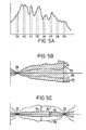
- Figure 5A is a diagram showing the spectral distribution for a xenon flash; figure 5B illustrates the effect of single point intensity normalization and Figure 5C illustrates the effect of two point normalization.
- Figure 1 is a schematic illustration of the circuit used to energize a xenon flashtube 1 in accordance with the invention. The flashtube consists of a glass enclosure 2 with electrodes extending into the enclosure filled with xenon gas. Electrode 4 acts as an anode and electrode 3 acts as a cathode. The flashtube also includes a
wisker 6 connected to the anode and extending downwardly and outwardly toward the enclosure wall. A film 5 is deposited on the outer surface of the enclosure starting in the region opposite the free end ofwisker 6, extending around the enclosure and down the side to connect to the cathode. The wisker and conductive film, described more fully in Goldberg Patent No. 3,758,819, are used to ionize the gaseous medium to trigger the arc in the flashtube. - Xenon flashtubes suitable for color spectrophotometric use are manufactured by U.S. Scientific Instruments type 2CR-n.
- The xenon flashtube is energized by a pulse discharge from a
capacitor 10. One plate of the capacitor is connected to anode 4 via the series combination of aninductance coil 12 and a diode string 13. The other plate of the capacitor is connected to cathode 3. The anode of a diode 14 is connected to the cathode 3 of the flashtube, and the cathode thereof is connected to the anode viacoil 12 and diode string 13. - The charging circuit for
capacitor 10 includes a transformer 7 and a full-wave bridge rectifier 8. The output of the bridge is connected acrosscapacitor 10 through a current limiting resistor 11 (100 ohms). - The circuit parameters are selected to provide a high current pulse discharge to energize the xenon flashtube to produce a flash of appropriate intensity for reflectance or transmittance spectrophotometric measurements. Capacitor 10 is preferably of a 100 microfarad size and is preferably charged to a potential of about 570 volts. When fully charged the capacitor has an energy content of about 15 joules with a peak power of about 100,000 watts.
- The trigger circuit for initiating an arc discharge includes a step-up transformer 22. The high voltage secondary of the transformer is connected across the anode and cathode 3-4 of the flashtube. One end of the primary winding is connected to the negative terminal of bridge 8 and the other end of the winding is connected to the positive bridge terminal via a capacitor 21 and a
resistor 20. A switch 23 (which can be a solid state switch like a silicon controlled rectifier) is connected across capacitor 21 and the primary winding of transformer 22. Another suitable trigger circuit is described in Ward Patent No. 3,355,625. - Assuming both
capacitors 10 and 21 are charged, then closure ofswitch 23 will provide a high intensity short duration flash. When the switch closes, capacitor 21 discharges to energize the primary of transformer 22 which in turn generates a potential on the secondary that tends to rise toward some high potential such as twelve kilovolts. Diodes 13 prevent this high potential from feeding back tofurther charge capacitor 10. When the potential across the anode-cathode circuit of the flashtube reaches 5-6 kilovolts, thewisker 6 and film 5 initiate ionization of the gaseous medium causing the gas to break down. This results in establishing an arc between electrodes 3 and 4 asmain capacitor 10 discharges viainductance 12, diodes 13, anode 4 and cathode 3. - If
coil 12 were omitted, as is conventional in prior art circuits, closure ofswitch 23 would result in a discharge of the nature shown by curve A in Fig. 2. The current flow through arc electrodes 3-4 would rise rapidly to about a 5,000 ampere peak and then diminish exponentially towards zero. The duration of the principal portion of the pulse is about 20-30 microseconds. The pulse diminishes substantially to zero in 50 microseconds. - The addition of
inductance coil 12 and diode 14 alters the discharge as indicated by curve B in Fig. 2 so that it has a lower peak current and a longer duration. With the coil in the circuit, whencapacitor 10 begins discharging, energy is first absorbed in the coil. The energy in the coil is thereafter dissipated and discharged into the flashtube by a current path through diode 14 bypassingcapacitor 10. - For the specific xenon tube and other circuit parameters as specified above, the preferred inductance coil includes 40 turns of tightly wound number 14 gauge wire wound around a 3/8 inch diameter core form. Satisfactory operating results are achieved with coils ranging from 10 turns to 100 turns. The corresponding inductances are in the range of 1 henry to 10 henrys. The preferred 40 turn coil has an inductance of about 3 henrys. For the larger coils it is preferable to use layered windings in order to reduce resistance in the main current path and to reduce the size of the coil. The same inductance can be achieved in a layered coil using fewer turns.
- When a 40 turn inductance coil as specified above is included in the circuit, the peak discharge current is reduced from 5,000 amperes to about 2,000 amperes as indicated in curve B in Fig. 2. The current drops substantially to zero at 80 microseconds. When used in spectrophotometry instruments peak currents in the range of 4,000 to 1,000 have been found to provide the desired results in accordance with the invention. These pulses have a duration in the range of 60 to 200 microseconds (based on substantially zero values).
- Figure 3A illustrates the appearance of a pair of
new electrodes - Figure 3B illustrates the appearance of the electrodes after use in prior type systems operated at about 5,000 ampere peak current without the
inductance coil 12 in the circuit. As can be seen in the drawing, electrodes 33-34 have deteriorated and, after about 100,000 flashes would appear having rounded ends 35 and 36. With a rounded electrode the arc may originate from different random sites on the electrode resulting in variations in the arc length, variations in the lateral location of the arc, and undesirable variations in the spectral distribution of the flash. Such rounded electrodes provide erratic illumination and are unsatisfactory for spectrophotometric instrumentation. - The unexpected electrode regeneration effect observed in actual practice when operating in accordance with the invention causes changes in the electrode surface structure as shown in Figure 3C. In operation enucleation sites develop on the conical end surface of
electrodes spheroidal nodules 39 and 40 as shown in the illustration. When the original point of the electrode is worn down and becomes rounded, one of the nodule points such as at 39 or 40 takes over as the electrode point from which the arc originates. While one nodule point is the point of origination for the arc, nodules in other regions attract material and tend to grow and eventually take over as the electrode point. In this fashion there is a continual regeneration of the electrode providing a stable site for arc origination on successive flashes. Since the arc originates from a specific controlled point during successive flashes, the arc tends to be stable in length and lateral location. - Fig. 4 shows a spectrophotometer used to make diffuse reflectance measurements throughout the visible spectrum in order to measure the color of a sample. This spectrophotometer includes a xenon flashtube 43 according to this invention. To provide diffuse illumination, a sample 41 is placed in an integrating sphere 42 which is a hollow sphere, the inside surface of which is covered with a white diffusing coating such as barium sulphate. Illumination is provided by the pulsed xenon flashtube. The xenon flashtube provides a short, intense pulse of iHumination. which drops to substantially zero in 80 microseconds. Because' of the short duration of sample illumination it is possible to measuœ moving samples, which typically move a negligible distance during the measurement. (See, e.g., G. P. Bentley et al U.S. Pat. No. 3,458,261). Also the high intensity and short pulse width renders an electronic system that is high-pass filtered insensitive to the effects of ambient light.
- Rays of illumination emanating from the source, such as rays A, B and C, strike the diffusely reflective wall of sphere 42 and are then diffusely reflected as, for example, is ray B. Some of these diffusely reflected rays strike the sample, but most strike another portion of the sphere a second time. This process repeats until all rays are absorbed by the sample or the sphere wall, or are reflected by the sample out of the sphere through circular aperture 44. Aperture 44 is located so as to pass rays reflected at a small angle, e.g., 8°, to the sample normal.
- The rays reflected from the sample are collected by a
lens 45 and focused throughslit 46. The purpose ofslit 46 is to restrict the angular spread of rays that proceed through the remainder of the optical system. The rays that pass through slit 46 are collimated by a lens 47 and impinge on dispersive elemenfs748, which may be a prism or a diffraction grating. Fig. 4 illustrates a reflective diffraction grating, which is the preferred dispersive element. - Grating 48 separates the incident light into its component wavelengths by deviating each wavelength by a unique angle. For example, the red rays, which have a wavelength of 700 nm, follow rays R and R', while the violet rays, which have a wavelength of 400 nm, follow rays V and V'. Lens 49 focuses these rays onto a linear array of discrete photodetectors 50, the red rays being focused at point R" and the violet rays at point V". All wavelengths between 400 nm and 700 nm are focused at points R" and V". The result is an image of the visible spectrum in the plane of photodetector array 50.
- It is possible to replace lens 47, grating 48 and lens 49 by a single diffraction grating that is manufactured on a concave spherical surface. The spherical surface behaves as a mirror with the ability to focus rays of light. The use of such a concave grating, therefore, is entirely equivalent to the use of the two lenses and the grating shown in Fig. 4. It is also possible to replace one of both of the lenses by concave mirrors, which perform the same imaging function as the lenses they replace.
- The photodetectors can be silicon photodiodes. Each photodiode measures only a narrow band of wavelengths. The width of this band depends on the width of
slit 46 and the width of each photodiode. The wavelengths measured depend on the position in the array, of the detectors. The number of detectors in the array is equal to the number of different wavelengths that are simultaneously measured. In a typical arrangement, there are 16 detectors that measure from 400 nm to 700 nm in equal intervals of 20 nm in accordance with CIE (Commission Internationale de L'eclairage; French International Commission on illumination) standards. It has been found that the width and the center-to-center spacing of the detectors affect the accuracy of the measurements for some colors. Accordingly, the ratio of the detector width to the center-to-center detector spacing should be in the range of 0.6 to 0.9 and preferably about 0.8 for best results. - A pair of
reference photodetectors 62 and 63 are located in holes in the sphere wall in order to monitor the intensity of the illuminating pulse. As will be described hereinafter in connection with Figs. 5A-5C, these detectors monitor the intensity at different wavelengths and, therefore, are provided with appropriate light filters. The signals derived from the detectors are used to "normalize" the signals derived from the detectors in array 50. - A portion of the sphere wall, known as the
specular port 53, can be removed by means of ahinge assembly 54 in order that the sample not be illuminated by rays that would be specularly reflected (i.e., reflected as off a mirror) and subsequently measured. When thespecular port 53 is removed, alight trap 55 prevents light that escapes through the hole in the sphere wall from deflecting about outside the sphere. The center of the specular port is located 8° from the sample normal, so that a ray of light emanating from the specular port will be specularly reflected in such a direction that it will pass out of the sphere through aperture 44. - In order to keep the spectrophotometer in correct calibration, a
prism 56 can be inserted into the path of rays that are reflected by the sample. This prism deviates rays from the sample so that they are deflected up (in a direction out of the plane of Fig. 4, thereby missing collectinglens 45. Instead, rays that are reflected from a portion of the sphere wall above the sample are directed intocollection lens 45 and are analyzed. Since the reflectance of the sphere wall is quite stable from day to day, this measurement can be used as a means of periodic calibration. - Fig. 5A illustrates the spectral distribution of the light from a xenon flashtube illumination with tungsten electrodes which, as can be seen, varies in intensity at different wavelengths. The light seems to include specific light bands as well as broad band distributions.
- For simplicity, only eight detector measurements (a)-(h) are shown in Fig. 5A whereas, as previously mentioned, a typical system is likely to include sixteen or more such measurements.
- If one of the detectors 62 (Fig. 4) is arranged to monitor the intensity of light at wavelength 70, as shown in Fig. 5B, this measured value is used by the processing electronics 51 (Fig. 4) to "normalize" for intensity variations. This is accomplished by dividing the measured values from the detectors 50 by the reference value measured by detector 62.
- By observing flashtube operations it has been found that in addition to intensity variations there are also spectral rocking variations such that the intensity of light at one end of the spectrum sometimes increases more than the intensity at the other end. Thus, if a single point intensity normalization is made at wavelength 70, for example, there may be deviations from the true value at other points in the spectrum. In general, as shown in Fig. 5B, these deviations could fall between the
lines - To compensate for the spectral shifts it is preferable to also normalize at least one additional point such as wavelength 73 as shown in Fig. 5C. Reference detector 62 is used for this purpose. The two monitoring points 70 and 73 should be well separated as shown.
- The preferred procedure for obtaining data for the spectral normalization is to use a standard white tile and record values for each of the
detectors 50 and 63 after intensity normalization (detector 62). From this data an average value can be determined for each of the detectors 50 corresponding to each of the different measurable values fromdetector 63. These average values are placed in a look-up table and used for the spectral normalization. In use on an unknown sample, when a value is measured bydetector 63 the correction factors corresponding to this measured value are obtained from the look-up table and used to modify the values obtained from the detectors 50. - With two point normalization as described above, correct values are assured at wavelengths 70 and 73, the normalization points, but some degree of deviation would still be expected at other points in the spectrum. This deviation, in exaggerated form, would be as indicated by the dashed
lines 74 and 75 in Fig. 5C. - When the flashtube circuit is modified as shown in Fig. 1 according to this invention it was found that a greater spectral shift results. As shown in Fig. 5B, the deviation would fall between the dotted lines 76-77 without the inductance but increase to the area between
lines - Surprisingly, however, it was found that even though the deviation after intensity normalization is greater with the modification according to the invention, the deviation after two-point normalization is less. As shown in Fig. 5C the maximum deviation is reduced from d2 to d3 as is shown by the shaded area in Fig. 5C. The reason for this unexpected improvement is unknown.
- Color spectrophotometric instruments are usually rated according to ability to repeat the same measurement. These ratings are in accordance with color difference values wherein a value of 1.0 is the just perceptible color difference detectable by the human eye. Repeatability is the RMS (root mean square) color difference value over a series of measurements on the same sample.
- With the prior systems, single point intensity normalization would give erratic results with color difference values as high as 1 or 2. Similar systems with two point normalization would normally be in the range of .17 to .25 color difference. With the modification according to this invention, after two-point normalization, the repeatability performance improved to the range of 0.09 to 0.15 color difference.
- The
processing electronics 51 preferably includes a sample and hold circuit and an analog- to-digital converter connected to each of thedetectors 50, 62 and 63, a read only memory (ROM) for the look-up table and a microprocessor programmed to carry out the normalization calculations indicated previously. The sample and hold circuits are controlled to provide a measurement window corresponding to the light pulse duration which would be between 60 and 200 microseconds and about 80 microseconds for the preferred embodiment illustrated in curve B in Fig. 2. - Alternatively, a hardwired digital logic system or an analog computational system could be used.
- In the foregoing description preferred embodiments have been described. It should be obvious, however, that there are numerous variations within the scope of this invention which is more particularly defined in the appended claims.
Claims (10)
Priority Applications (3)
| Application Number | Priority Date | Filing Date | Title |
|---|---|---|---|
| EP83108329A EP0134273B1 (en) | 1983-08-24 | 1983-08-24 | Pulse light stabilization for color spectrophotometric instrumentation |
| DE8383108329T DE3377393D1 (en) | 1983-08-24 | 1983-08-24 | Pulse light stabilization for color spectrophotometric instrumentation |
| AT83108329T ATE35761T1 (en) | 1983-08-24 | 1983-08-24 | LIGHT PULSE STABILIZATION FOR COLOR SPECTROPHOTOMETER. |
Applications Claiming Priority (1)
| Application Number | Priority Date | Filing Date | Title |
|---|---|---|---|
| EP83108329A EP0134273B1 (en) | 1983-08-24 | 1983-08-24 | Pulse light stabilization for color spectrophotometric instrumentation |
Publications (2)
| Publication Number | Publication Date |
|---|---|
| EP0134273A1 EP0134273A1 (en) | 1985-03-20 |
| EP0134273B1 true EP0134273B1 (en) | 1988-07-13 |
Family
ID=8190640
Family Applications (1)
| Application Number | Title | Priority Date | Filing Date |
|---|---|---|---|
| EP83108329A Expired EP0134273B1 (en) | 1983-08-24 | 1983-08-24 | Pulse light stabilization for color spectrophotometric instrumentation |
Country Status (3)
| Country | Link |
|---|---|
| EP (1) | EP0134273B1 (en) |
| AT (1) | ATE35761T1 (en) |
| DE (1) | DE3377393D1 (en) |
Families Citing this family (2)
| Publication number | Priority date | Publication date | Assignee | Title |
|---|---|---|---|---|
| IT1216681B (en) * | 1988-03-31 | 1990-03-08 | Maxmeyer Duco Mm D Spa | PORTABLE SPECTROPHOMETER. |
| US6219140B1 (en) * | 1998-12-16 | 2001-04-17 | Eastman Kodak Company | Apparatus for compensation for spectral fluctuation of a light source and a scanner incorporating said apparatus |
Family Cites Families (4)
| Publication number | Priority date | Publication date | Assignee | Title |
|---|---|---|---|---|
| DE1461217B2 (en) * | 1964-07-17 | 1971-02-04 | Jagenberg-Werke AG, 4000 Dussel dorf | Device in a cross-cutting machine for sorting faulty sheets or sheet packages |
| US3458261A (en) * | 1964-09-25 | 1969-07-29 | Kollmorgen Corp | Pulsed light photometric apparatus for measuring light characteristics of moving materials |
| US3758819A (en) * | 1971-12-27 | 1973-09-11 | Scient Instr Inc | Flash discharge apparatus and method |
| US4051411A (en) * | 1976-09-02 | 1977-09-27 | General Electric Company | Discharge lamp operating circuit |
-
1983
- 1983-08-24 AT AT83108329T patent/ATE35761T1/en not_active IP Right Cessation
- 1983-08-24 EP EP83108329A patent/EP0134273B1/en not_active Expired
- 1983-08-24 DE DE8383108329T patent/DE3377393D1/en not_active Expired
Also Published As
| Publication number | Publication date |
|---|---|
| EP0134273A1 (en) | 1985-03-20 |
| DE3377393D1 (en) | 1988-08-18 |
| ATE35761T1 (en) | 1988-07-15 |
Similar Documents
| Publication | Publication Date | Title |
|---|---|---|
| US5793486A (en) | Dual spectrometer color sensor | |
| CA1115545A (en) | Spectrophotometer | |
| EP1399694B1 (en) | Led luminaire with light sensor configurations for optical feedback | |
| DE69907594T2 (en) | WAVELENGTH SYSTEM FOR AN EXCIMER LASER | |
| DE60223928T2 (en) | SPECTROMETER USING A SPECTRAL SEPARATION METHOD | |
| EP0833373B1 (en) | Emission device comprising a mercury lamp of the short ARC type | |
| EP0134273A1 (en) | Pulse light stabilization for color spectrophotometric instrumentation | |
| AU542300B2 (en) | Pulse light stabilization for color spectrophotometric instrumentation | |
| US5109248A (en) | Variable color-output strobe for photographic apparatus | |
| EP0077776A1 (en) | Pulse light stabilization for color spectrophotometric instrumentation | |
| EP0185405B1 (en) | Analytical photometer, in particular multi-channel, applied to a centrifugal system adapted to perform practically simultaneous determination of the presence of different substances in a certain number of samples | |
| US4594614A (en) | Film video player with electronic strobe light | |
| US3264931A (en) | Automatic brightness pyrometers | |
| US4701664A (en) | Mercury arc lamp suitable for inclusion in a flow cytometry apparatus | |
| US5920389A (en) | Multi-channel spectro-photometers | |
| Ohno et al. | Characterization of modified FEL quartz-halogen lamps for photometric standards | |
| EP0206840B1 (en) | Semiconductor light position detector for rangefinder | |
| US5903346A (en) | Analysis system | |
| US4523096A (en) | Liquid chromatography apparatus | |
| US20030164941A1 (en) | System for measuring radiance | |
| Sperling et al. | A stabilized transfer-standard system for spectral irradiance | |
| Smith et al. | High current pulsing of a xenon arc lamp for electrothermal atomic absorption spectrometry using a linear photodiode array | |
| US7365833B1 (en) | System for measuring radiance, transmittance and reflectance | |
| Bless et al. | Astronomical Radiation Measurements. I. Spectrophotometric Standards for Astronomical Use | |
| SU1103305A1 (en) | Gaseous-discharge light source |
Legal Events
| Date | Code | Title | Description |
|---|---|---|---|
| PUAI | Public reference made under article 153(3) epc to a published international application that has entered the european phase |
Free format text: ORIGINAL CODE: 0009012 |
|
| AK | Designated contracting states |
Designated state(s): AT CH DE FR GB LI NL SE |
|
| 17P | Request for examination filed |
Effective date: 19850916 |
|
| 17Q | First examination report despatched |
Effective date: 19870212 |
|
| GRAA | (expected) grant |
Free format text: ORIGINAL CODE: 0009210 |
|
| AK | Designated contracting states |
Kind code of ref document: B1 Designated state(s): AT CH DE FR GB LI NL SE |
|
| PG25 | Lapsed in a contracting state [announced via postgrant information from national office to epo] |
Ref country code: SE Effective date: 19880713 |
|
| REF | Corresponds to: |
Ref document number: 35761 Country of ref document: AT Date of ref document: 19880715 Kind code of ref document: T |
|
| REF | Corresponds to: |
Ref document number: 3377393 Country of ref document: DE Date of ref document: 19880818 |
|
| ET | Fr: translation filed | ||
| PLBE | No opposition filed within time limit |
Free format text: ORIGINAL CODE: 0009261 |
|
| STAA | Information on the status of an ep patent application or granted ep patent |
Free format text: STATUS: NO OPPOSITION FILED WITHIN TIME LIMIT |
|
| 26N | No opposition filed | ||
| REG | Reference to a national code |
Ref country code: CH Ref legal event code: PUE Owner name: KOLLMORGEN CORPORATION |
|
| NLS | Nl: assignments of ep-patents |
Owner name: KOLLMORGEN CORPORATION TE SIMSBURY, CONNECTICUT, V |
|
| REG | Reference to a national code |
Ref country code: FR Ref legal event code: TP |
|
| REG | Reference to a national code |
Ref country code: GB Ref legal event code: 732 |
|
| PGFP | Annual fee paid to national office [announced via postgrant information from national office to epo] |
Ref country code: FR Payment date: 19920812 Year of fee payment: 10 |
|
| PGFP | Annual fee paid to national office [announced via postgrant information from national office to epo] |
Ref country code: AT Payment date: 19920828 Year of fee payment: 10 |
|
| PGFP | Annual fee paid to national office [announced via postgrant information from national office to epo] |
Ref country code: NL Payment date: 19920831 Year of fee payment: 10 |
|
| PG25 | Lapsed in a contracting state [announced via postgrant information from national office to epo] |
Ref country code: AT Effective date: 19930824 |
|
| REG | Reference to a national code |
Ref country code: GB Ref legal event code: 732E |
|
| PG25 | Lapsed in a contracting state [announced via postgrant information from national office to epo] |
Ref country code: NL Effective date: 19940301 |
|
| REG | Reference to a national code |
Ref country code: CH Ref legal event code: PUE Owner name: KOLLMORGEN INSTRUMENTS CORPORATION |
|
| NLV4 | Nl: lapsed or anulled due to non-payment of the annual fee | ||
| PG25 | Lapsed in a contracting state [announced via postgrant information from national office to epo] |
Ref country code: FR Effective date: 19940429 |
|
| REG | Reference to a national code |
Ref country code: FR Ref legal event code: ST |
|
| REG | Reference to a national code |
Ref country code: CH Ref legal event code: PUE Owner name: KOLLMORGEN INSTRUMENTS CORPORATION TRANSFER- GRETA |
|
| REG | Reference to a national code |
Ref country code: GB Ref legal event code: 732E |
|
| PGFP | Annual fee paid to national office [announced via postgrant information from national office to epo] |
Ref country code: GB Payment date: 19990810 Year of fee payment: 17 |
|
| PGFP | Annual fee paid to national office [announced via postgrant information from national office to epo] |
Ref country code: CH Payment date: 19990908 Year of fee payment: 17 |
|
| PGFP | Annual fee paid to national office [announced via postgrant information from national office to epo] |
Ref country code: DE Payment date: 19991102 Year of fee payment: 17 |
|
| PG25 | Lapsed in a contracting state [announced via postgrant information from national office to epo] |
Ref country code: GB Free format text: LAPSE BECAUSE OF NON-PAYMENT OF DUE FEES Effective date: 20000824 |
|
| PG25 | Lapsed in a contracting state [announced via postgrant information from national office to epo] |
Ref country code: LI Free format text: LAPSE BECAUSE OF NON-PAYMENT OF DUE FEES Effective date: 20000831 Ref country code: CH Free format text: LAPSE BECAUSE OF NON-PAYMENT OF DUE FEES Effective date: 20000831 |
|
| REG | Reference to a national code |
Ref country code: CH Ref legal event code: PL |
|
| GBPC | Gb: european patent ceased through non-payment of renewal fee |
Effective date: 20000824 |
|
| PG25 | Lapsed in a contracting state [announced via postgrant information from national office to epo] |
Ref country code: DE Free format text: LAPSE BECAUSE OF NON-PAYMENT OF DUE FEES Effective date: 20010501 |