EP0134239B1 - Emergency rescue device - Google Patents
Emergency rescue device Download PDFInfo
- Publication number
- EP0134239B1 EP0134239B1 EP84900813A EP84900813A EP0134239B1 EP 0134239 B1 EP0134239 B1 EP 0134239B1 EP 84900813 A EP84900813 A EP 84900813A EP 84900813 A EP84900813 A EP 84900813A EP 0134239 B1 EP0134239 B1 EP 0134239B1
- Authority
- EP
- European Patent Office
- Prior art keywords
- container
- flotation device
- cam
- signal buoy
- personal flotation
- Prior art date
- Legal status (The legal status is an assumption and is not a legal conclusion. Google has not performed a legal analysis and makes no representation as to the accuracy of the status listed.)
- Expired - Lifetime
Links
Images
Classifications
-
- B—PERFORMING OPERATIONS; TRANSPORTING
- B63—SHIPS OR OTHER WATERBORNE VESSELS; RELATED EQUIPMENT
- B63C—LAUNCHING, HAULING-OUT, OR DRY-DOCKING OF VESSELS; LIFE-SAVING IN WATER; EQUIPMENT FOR DWELLING OR WORKING UNDER WATER; MEANS FOR SALVAGING OR SEARCHING FOR UNDERWATER OBJECTS
- B63C9/00—Life-saving in water
- B63C9/22—Devices for holding or launching life-buoys, inflatable life-rafts, or other floatable life-saving equipment
- B63C9/23—Containers for inflatable life-saving equipment
-
- B—PERFORMING OPERATIONS; TRANSPORTING
- B63—SHIPS OR OTHER WATERBORNE VESSELS; RELATED EQUIPMENT
- B63C—LAUNCHING, HAULING-OUT, OR DRY-DOCKING OF VESSELS; LIFE-SAVING IN WATER; EQUIPMENT FOR DWELLING OR WORKING UNDER WATER; MEANS FOR SALVAGING OR SEARCHING FOR UNDERWATER OBJECTS
- B63C9/00—Life-saving in water
- B63C9/08—Life-buoys, e.g. rings; Life-belts, jackets, suits, or the like
-
- B—PERFORMING OPERATIONS; TRANSPORTING
- B63—SHIPS OR OTHER WATERBORNE VESSELS; RELATED EQUIPMENT
- B63C—LAUNCHING, HAULING-OUT, OR DRY-DOCKING OF VESSELS; LIFE-SAVING IN WATER; EQUIPMENT FOR DWELLING OR WORKING UNDER WATER; MEANS FOR SALVAGING OR SEARCHING FOR UNDERWATER OBJECTS
- B63C9/00—Life-saving in water
- B63C9/21—Boats, rafts, buoys or the like, characterised by signalling means, e.g. lights, reflectors
-
- B—PERFORMING OPERATIONS; TRANSPORTING
- B63—SHIPS OR OTHER WATERBORNE VESSELS; RELATED EQUIPMENT
- B63C—LAUNCHING, HAULING-OUT, OR DRY-DOCKING OF VESSELS; LIFE-SAVING IN WATER; EQUIPMENT FOR DWELLING OR WORKING UNDER WATER; MEANS FOR SALVAGING OR SEARCHING FOR UNDERWATER OBJECTS
- B63C9/00—Life-saving in water
- B63C9/22—Devices for holding or launching life-buoys, inflatable life-rafts, or other floatable life-saving equipment
-
- B—PERFORMING OPERATIONS; TRANSPORTING
- B63—SHIPS OR OTHER WATERBORNE VESSELS; RELATED EQUIPMENT
- B63C—LAUNCHING, HAULING-OUT, OR DRY-DOCKING OF VESSELS; LIFE-SAVING IN WATER; EQUIPMENT FOR DWELLING OR WORKING UNDER WATER; MEANS FOR SALVAGING OR SEARCHING FOR UNDERWATER OBJECTS
- B63C9/00—Life-saving in water
- B63C2009/0023—Particular features common to inflatable life-saving equipment
- B63C2009/0029—Inflation devices comprising automatic activation means, e.g. for puncturing gas-generating cartridges
- B63C2009/0035—Inflation devices comprising automatic activation means, e.g. for puncturing gas-generating cartridges activated by deployment of inflatable life-saving equipment
Definitions
- This invention generally relates to emergency devices to assist in the rescue of persons who have fallen overboard in deep water.
- it relates to location and flotation devices which can be sent into the water immediately after the emergency is discovered.
- Prior art emergency location and flotation devices have one or more disadvantages such as difficulty of mounting on a ship, time consuming deployment, excessive weight and poor visibility.
- US 3,754,291 shows a combination device in the form of a boat-mounted container for a buoy, a sea anchor, a flotable, telescoping flag and a strobe light. If a person falls overboard, the container is opened and the buoy and other devices fall therefrom into the water; the telescoping flag deploys and the light is activated. The anchor holds the buoy in place while the flag and light indicate the position of the buoy and the person holding onto it.
- the object of the present invention is to overcome the above drawbacks and to provide a compact readily mountable emergency location and flotation device which can be readily and reliably deployed.
- This invention comprises broadly an assembly of an inflatable location or flotation device in a container mounted on the deck of a ship.
- the container has a front flap which is releasably secured to the walls of the container.
- a pull on a strap attached to the flap opens the container and permits the stored device to fall into the water.
- Means are provided to automatically inflate the devices with a gas under pressure, as for example, carbon dioxide.
- the container holds both inflatable location and inflatable flotation devices tethered together.
- identification and signal devices be included and, for example, a strobe light, air horn, whistle, flares, dye marker, distress flag, radar reflector panels, helium balloon and sea anchor. Where appropriate, such identification and signal devices may also be tethered to the inflatable devices.
- the container is attached by straps to the rail on the deck of the ship.
- a release strap extends from the bottom of the front flat to the top of the container where it is connected to a line attached to the deck.
- a pull on the line immediately pulls up the front flap permitting the stored devices to fall into the water.
- the front panel is preferably releasably attached as, for example, with Velcro to an upward skirt extension of the bottom panel. When the front flap is pulled up, the skirt and bottom panel drop down. A metal snap between the front panel and the skirt insures that the container will not open accidentally but only when there is sufficient pull.
- the inflatable location device is preferably a signal cone with a weight in the bottom to keep it vertical when inflated.
- Inflation of the devices is accomplished by releasing gas stored under pressure. Such release is accomplished either by the action of the water on the release mechanism or by mechanical release triggered by the pull on lines attached to the container as the contents fall into the water. In the latter instance, for example, a spring loaded puncture pin is driven into the opening of the vessel under pressure, thus permitting inflation.
- the driving is accomplished by a pivoted arm, one end of which is connected to the container. As the devices fall, the pull causes the arm to pivot and then fall away. The inflation thus starts before the devices hit the water. Water-soluble releases can also be used since they are activated immediately upon striking the water.
- the container 100 comprises a back wall 100a vertically attached to two side walls 100b.
- a top wall 100c has a foldable, flexible front extension 100d.
- Extending from the bottom of back wall 100a is a bottom panel 102 attached only along one edge and having a foldable skirt extension 103a provided with a fastener means 102b as for example, Velcro.
- Front flexible panel 100d has cooperating fastening means 100dd.
- Panel 100d also has an external metal snap 102a to which is attached strap 100f extending through loop 109 to ring 101 attached to release line 14 which in turn is held on the deck 96 of the vessel. Pulling on the release line 14 causes the flexible front panel 100d to be separated from the skirt 103a and pulled up. The skirt with the bottom panel 102 drops back and down and the contents of the container drop down to the water in a very rapid fashion.
- a collapsed inflatable horseshoe flotation device 111 Stored within the container is a collapsed inflatable horseshoe flotation device 111, a collapsed inflatable signal cone 104, a weight 105 in the signal cone, carbon dioxide storage means 301 and carbon dioxide valve release means 300 associated with said carbon dioxide storge means.
- the signal cone and horseshoe flotation device are tethered together with lines 109 and 110.
- Associated with the inflatable cone is a signal flag 108, a water-activated light 120, reflective panels 121 and a drogue 119.
- the container is preferably made with a vacuum- formed plastic inner liner covered with nylon pack cloth.
- FIG. 10 An alternative method of automatic inflation is to use as illustrated in Fig. 10 a water-soluble release which permits spring 207 to drive puncture pin 202 into carbon dioxide container 201, utilizing a fixed cam lever 203. Both devices have as a safety a manual activator 209 in the event that the automatic inflation fails.
- Signal cone 104 when inflated sits vertically in the water. Its weight compartment 105a has a zipper 106 for insertion of weight 105 and is separated from the carbon dioxide compartment.
- the cone 104 is preferably neoprene-coated nylon 107 with aluminized mylar coating 107a for radar reflection. It has connections 119b for lines 119a holding stabilizing sea anchor 119.
- a light 120 is mounted in the upper end and makes the reflective panels 121 visible. Power for the light 120 is provided by a water-activated battery 117.
- Signal flag 108 is mounted near the top of the cone.
- a manual inflation tube 118 is provided.
- the horseshoe flotation device also has a manual inflation tube 114, a pocket 113 for ancillary devices, and a line 115 which connects the snap 115b to snap 115a to hold the survivor 13 within the flotation device.
- ancillary devices are a helium balloon 127, a strobe light 120b and a flare 120.
- An alternative structure for anchoring the signal cone is to form the bottom of the inflation chamber 104a as an inverted cone 107b terminating in chamber 107b containing a lead weight 205b.
Landscapes
- Engineering & Computer Science (AREA)
- Mechanical Engineering (AREA)
- Ocean & Marine Engineering (AREA)
- Emergency Lowering Means (AREA)
- Looms (AREA)
- Vending Machines For Individual Products (AREA)
- Alarm Systems (AREA)
Abstract
Description
- This invention generally relates to emergency devices to assist in the rescue of persons who have fallen overboard in deep water. In particular it relates to location and flotation devices which can be sent into the water immediately after the emergency is discovered.
- Prior art emergency location and flotation devices have one or more disadvantages such as difficulty of mounting on a ship, time consuming deployment, excessive weight and poor visibility.
- US 3,754,291 shows a combination device in the form of a boat-mounted container for a buoy, a sea anchor, a flotable, telescoping flag and a strobe light. If a person falls overboard, the container is opened and the buoy and other devices fall therefrom into the water; the telescoping flag deploys and the light is activated. The anchor holds the buoy in place while the flag and light indicate the position of the buoy and the person holding onto it.
- Another similar emergency rescue assembly is described in US-A-4063323 which comprises the features of the first part of claim 1.
- The object of the present invention is to overcome the above drawbacks and to provide a compact readily mountable emergency location and flotation device which can be readily and reliably deployed.
- This object is achieved by means of an assembly according to the appended claim 1. Further features of the invention and preferred embodiments of the same are stated in the appended subclaims.
- This invention comprises broadly an assembly of an inflatable location or flotation device in a container mounted on the deck of a ship. The container has a front flap which is releasably secured to the walls of the container. A pull on a strap attached to the flap opens the container and permits the stored device to fall into the water. Means are provided to automatically inflate the devices with a gas under pressure, as for example, carbon dioxide.
- In a preferred form, the container holds both inflatable location and inflatable flotation devices tethered together. In addition, it is preferred that identification and signal devices be included and, for example, a strobe light, air horn, whistle, flares, dye marker, distress flag, radar reflector panels, helium balloon and sea anchor. Where appropriate, such identification and signal devices may also be tethered to the inflatable devices.
- In a preferred form, the container is attached by straps to the rail on the deck of the ship. A release strap extends from the bottom of the front flat to the top of the container where it is connected to a line attached to the deck. Thus, a pull on the line immediately pulls up the front flap permitting the stored devices to fall into the water. The front panel is preferably releasably attached as, for example, with Velcro to an upward skirt extension of the bottom panel. When the front flap is pulled up, the skirt and bottom panel drop down. A metal snap between the front panel and the skirt insures that the container will not open accidentally but only when there is sufficient pull.
- The inflatable location device is preferably a signal cone with a weight in the bottom to keep it vertical when inflated. Inflation of the devices is accomplished by releasing gas stored under pressure. Such release is accomplished either by the action of the water on the release mechanism or by mechanical release triggered by the pull on lines attached to the container as the contents fall into the water. In the latter instance, for example, a spring loaded puncture pin is driven into the opening of the vessel under pressure, thus permitting inflation. The driving is accomplished by a pivoted arm, one end of which is connected to the container. As the devices fall, the pull causes the arm to pivot and then fall away. The inflation thus starts before the devices hit the water. Water-soluble releases can also be used since they are activated immediately upon striking the water.
- An embodiment of this invention will be apparent from the description taken together with the appended drawings.
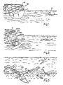
- Fig. 1 is a view showing the container with stored flotation devices mounted on the rail of a boat and with its release line attached to the deck.
- Fig. 2 shows the same view as Fig. 1 after the devices have been dropped from the container.
- Fig. 3 shows the devices partially inflated on the surface of the water.
- Fig. 4 shows the devices fully inflated with the survivor in position on the horseshoe.
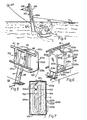
- Fig. 5 is a partial perspective view of a preferred form of the invention in stowed condition mounted on the rail of a boat with its release line attached to the deck.
- Fig. 6 is an opposite perspective view of Fig. 5 showing the attachment of the front panel to the skirt extension of the bottom panel.
- Fig. 7 is a schematic cross section along line 7-7 of Fig. 6 showing the packing of the inflatable devices in the container.
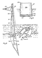
- Fig. 8 is an enlarged detailed view of the fully- inflated tethered devices in the water.
- Fig. 9 is a partial section along line 9-9 showing the bottom portion of the signal cone.
- Fig. 9A is a partial section showing an alternative construction of the signal cone.
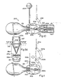
- Fig. 10 is a schematic section showing the operation of the water-soluble release mechanism for inflating with gas under pressure.
- Fig. 11 is a schematic section showing the mechanism for mechanically releasing the gas pressure.
- Referring now to the drawings, a
preferred embodiment 10 of this invention is shown attached to therail 12 of vessel 11 withstraps 97 and 98. Thecontainer 100 comprises a back wall 100a vertically attached to twoside walls 100b. Atop wall 100c has a foldable,flexible front extension 100d. Extending from the bottom of back wall 100a is abottom panel 102 attached only along one edge and having afoldable skirt extension 103a provided with a fastener means 102b as for example, Velcro. Frontflexible panel 100d has cooperating fastening means 100dd.Panel 100d also has an external metal snap 102a to which is attachedstrap 100f extending throughloop 109 toring 101 attached torelease line 14 which in turn is held on thedeck 96 of the vessel. Pulling on therelease line 14 causes theflexible front panel 100d to be separated from theskirt 103a and pulled up. The skirt with thebottom panel 102 drops back and down and the contents of the container drop down to the water in a very rapid fashion. - Stored within the container is a collapsed inflatable horseshoe flotation device 111, a collapsed
inflatable signal cone 104, aweight 105 in the signal cone, carbon dioxide storage means 301 and carbon dioxide valve release means 300 associated with said carbon dioxide storge means. The signal cone and horseshoe flotation device are tethered together withlines - Also stored in the container are other rescue devices such as an air horn, whistle, dye marker, aerial flare, mini strobe light, signal light and personal light. Associated with the inflatable cone is a
signal flag 108, a water-activatedlight 120,reflective panels 121 and adrogue 119. The container is preferably made with a vacuum- formed plastic inner liner covered with nylon pack cloth. - When the
release line 14 is pulled, the contents of thecontainer 100 immediately fall out and the inflatable cone and horseshoe flotation device are automatically inflated as illustrated more particularly in Figs. 2 and 11. Lanyards 104a are attached to cam-shaped levers 300a having cut-out 300b which mount onpivot 302b. When the contents are dropped out of the container, the cam-shaped levers 300a rotate so as to drivepuncture pin 302 into thecarbon dioxide reservoir 301 and then separate from thepivot 302b. Inflatation thus begins while the cone and horseshoe device are still falling. - An alternative method of automatic inflation is to use as illustrated in Fig. 10 a water-soluble release which permits
spring 207 to drivepuncture pin 202 intocarbon dioxide container 201, utilizing a fixed cam lever 203. Both devices have as a safety amanual activator 209 in the event that the automatic inflation fails. -
Signal cone 104 when inflated sits vertically in the water. Its weight compartment 105a has azipper 106 for insertion ofweight 105 and is separated from the carbon dioxide compartment. Thecone 104 is preferably neoprene-coatednylon 107 with aluminized mylar coating 107a for radar reflection. It hasconnections 119b for lines 119a holding stabilizingsea anchor 119. A light 120 is mounted in the upper end and makes thereflective panels 121 visible. Power for the light 120 is provided by a water-activatedbattery 117.Signal flag 108 is mounted near the top of the cone. Amanual inflation tube 118 is provided. - The horseshoe flotation device also has a manual inflation tube 114, a
pocket 113 for ancillary devices, and aline 115 which connects thesnap 115b to snap 115a to hold thesurvivor 13 within the flotation device. Among the ancillary devices are ahelium balloon 127, astrobe light 120b and aflare 120. - An alternative structure for anchoring the signal cone, as illustrated in Fig. 9A, is to form the bottom of the
inflation chamber 104a as aninverted cone 107b terminating inchamber 107b containing a lead weight 205b.
Claims (7)
Applications Claiming Priority (2)
| Application Number | Priority Date | Filing Date | Title |
|---|---|---|---|
| US462213 | 1983-01-31 | ||
| US06/462,213 US4498879A (en) | 1983-01-31 | 1983-01-31 | Emergency rescue device |
Publications (3)
| Publication Number | Publication Date |
|---|---|
| EP0134239A1 EP0134239A1 (en) | 1985-03-20 |
| EP0134239A4 EP0134239A4 (en) | 1986-04-15 |
| EP0134239B1 true EP0134239B1 (en) | 1990-03-14 |
Family
ID=23835601
Family Applications (1)
| Application Number | Title | Priority Date | Filing Date |
|---|---|---|---|
| EP84900813A Expired - Lifetime EP0134239B1 (en) | 1983-01-31 | 1984-01-23 | Emergency rescue device |
Country Status (8)
| Country | Link |
|---|---|
| US (1) | US4498879A (en) |
| EP (1) | EP0134239B1 (en) |
| JP (1) | JPS60500441A (en) |
| AU (1) | AU551536B2 (en) |
| CA (1) | CA1204630A (en) |
| DE (1) | DE3481601D1 (en) |
| IT (1) | IT1177523B (en) |
| WO (1) | WO1984002891A1 (en) |
Families Citing this family (34)
| Publication number | Priority date | Publication date | Assignee | Title |
|---|---|---|---|---|
| US4560356A (en) * | 1983-01-31 | 1985-12-24 | Halkey-Roberts Corporation | Personal flotation device |
| DE3604857C1 (en) * | 1986-02-15 | 1987-08-06 | Messerschmitt Boelkow Blohm | Pack sack and its arrangement for easy access storage of a life jacket, preferably in an aircraft |
| US4702715A (en) * | 1986-06-06 | 1987-10-27 | Winick Alan L | Automatic emergency rescue apparatus |
| FR2609444B1 (en) * | 1987-01-09 | 1991-06-07 | Simon Henri | METHOD AND DEVICE FOR WIDENING SAFETY EQUIPMENT ON SHIPS |
| US5102360A (en) * | 1990-06-27 | 1992-04-07 | Eycleshimer Robert G | Shipboard container for survival equipment |
| US5245943A (en) * | 1992-03-02 | 1993-09-21 | Hull Harold L | Land or water S.O.S. signaling device |
| US5192238A (en) * | 1992-07-14 | 1993-03-09 | Brown John B | Self-activated man overboard recovery system |
| US5297576A (en) * | 1992-10-16 | 1994-03-29 | Halkey-Roberts Corporation | Oral inflation and relief tube |
| JPH06211185A (en) * | 1993-01-14 | 1994-08-02 | Takata Kk | Life preserver |
| US5257954A (en) * | 1993-01-19 | 1993-11-02 | Gregory G. Steiner | Rescue buoy package |
| US6195039B1 (en) * | 1997-11-26 | 2001-02-27 | Robert T. Glass, Jr. | Location signalling apparatus |
| FR2780023B1 (en) * | 1998-06-23 | 2000-08-11 | Michel Pons | ON-BOARD DEVICE FOR RECOVERING A MAN OVERSEAS FOR THE SELF-RECOVERY OF A CONSCIOUS VICTIM |
| US6409561B1 (en) * | 2000-09-29 | 2002-06-25 | John C. Ibasfalean | Remote activated water self rescue system |
| FR2817532A1 (en) * | 2000-12-01 | 2002-06-07 | Jean Jacques Caillon | Rescue location arm, for rescuing endangered person from sea, comprises strong telescopic expanding tubes, cylindrical radar reflector, orange flag, and stroboscopic lamp |
| FR2817533A1 (en) * | 2000-12-01 | 2002-06-07 | Jean Jacques Caillon | Rescue arm mechanism, for signaling fall of person into sea, has floating arm with telescopic section having automatic deployment activated by spring in lower tube |
| EP1216919A1 (en) * | 2000-12-20 | 2002-06-26 | XM Yachting Limited | A horseshoe lifebuoy |
| US6558218B1 (en) | 2002-02-27 | 2003-05-06 | The United States Of America As Represented By The Secretary Of The Navy | Overboard rescue system |
| US6749473B1 (en) | 2002-10-30 | 2004-06-15 | Kitty Lower | Extensible safety signal device |
| US6863016B2 (en) * | 2002-12-18 | 2005-03-08 | Scott M. Biemiller | Apparatus and method for storing and accessing personal floatation devices and/or other articles |
| JP3979988B2 (en) * | 2003-11-28 | 2007-09-19 | 勝己 池田 | Folding retractable float |
| US7047966B2 (en) * | 2004-07-06 | 2006-05-23 | Stewart Robert E | Lifesaving floatation and breathing device |
| US7063034B2 (en) * | 2004-08-10 | 2006-06-20 | Watermark Paddlesports, Inc. | Spray skirt for watercraft |
| US7364486B2 (en) * | 2005-07-26 | 2008-04-29 | Michael Lawrence Serpa | Water rescue device |
| US20070238373A1 (en) * | 2006-04-07 | 2007-10-11 | Lars H Henrikson | Buoyant visibility device |
| WO2010051596A1 (en) * | 2008-11-07 | 2010-05-14 | Andrew Raven | Buoyancy device |
| WO2010135762A1 (en) * | 2009-04-08 | 2010-12-02 | Ross Spencer | Marine safety device |
| US20130043092A1 (en) * | 2011-08-17 | 2013-02-21 | Thomas W. Clardy | Integrated highly reliable person overboard self-rescue system |
| US9284030B2 (en) * | 2013-10-28 | 2016-03-15 | Jonathan Ganz | Man overboard apparatus and method |
| US9233741B2 (en) | 2013-11-18 | 2016-01-12 | William Lee | Life saving dan buoy |
| CN105852817B (en) * | 2015-01-20 | 2018-10-26 | 中国人民解放军第二军医大学 | Positioning, vital sign monitoring and rescue method in the cabin of crewman sea |
| EP3468863B1 (en) * | 2016-06-13 | 2023-05-03 | Motonautica F.LLI Ranieri SRL | Water rescue system |
| US10259547B1 (en) | 2017-02-02 | 2019-04-16 | George Kiel | Personal flotation device |
| ES1184333Y (en) * | 2017-02-08 | 2017-08-23 | Leon Arteta Saul De | PORTABLE HOLSTER HOLSTER COVER |
| US12448096B2 (en) * | 2023-02-02 | 2025-10-21 | Lary Z Enterprises, Inc. | Weight pocket liner for buoyancy control device (BCD) |
Family Cites Families (5)
| Publication number | Priority date | Publication date | Assignee | Title |
|---|---|---|---|---|
| US2264321A (en) * | 1939-12-26 | 1941-12-02 | Frank G Manson | Lifesaving apparatus |
| JPS466340Y1 (en) * | 1967-04-26 | 1971-03-05 | ||
| US3754291A (en) * | 1971-11-26 | 1973-08-28 | Del Amo Enterprises Inc | Quick release life saving equipment |
| FR2267928B1 (en) * | 1974-04-17 | 1980-05-23 | Niemann Wolfgang | |
| US4063323A (en) * | 1977-02-14 | 1977-12-20 | Salvarezza Robert M | Ring buoy with automatic separation of smoke signal buoy from strobe light buoy |
-
1983
- 1983-01-31 US US06/462,213 patent/US4498879A/en not_active Expired - Fee Related
-
1984
- 1984-01-20 CA CA000445789A patent/CA1204630A/en not_active Expired
- 1984-01-23 JP JP59500893A patent/JPS60500441A/en active Pending
- 1984-01-23 DE DE8484900813T patent/DE3481601D1/en not_active Expired - Lifetime
- 1984-01-23 AU AU24973/84A patent/AU551536B2/en not_active Ceased
- 1984-01-23 EP EP84900813A patent/EP0134239B1/en not_active Expired - Lifetime
- 1984-01-23 WO PCT/US1984/000105 patent/WO1984002891A1/en not_active Ceased
- 1984-01-30 IT IT47616/84A patent/IT1177523B/en active
Also Published As
| Publication number | Publication date |
|---|---|
| IT8447616A1 (en) | 1985-07-30 |
| EP0134239A1 (en) | 1985-03-20 |
| IT1177523B (en) | 1987-08-26 |
| WO1984002891A1 (en) | 1984-08-02 |
| AU551536B2 (en) | 1986-05-01 |
| JPS60500441A (en) | 1985-04-04 |
| AU2497384A (en) | 1984-08-15 |
| DE3481601D1 (en) | 1990-04-19 |
| EP0134239A4 (en) | 1986-04-15 |
| IT8447616A0 (en) | 1984-01-30 |
| CA1204630A (en) | 1986-05-20 |
| US4498879A (en) | 1985-02-12 |
Similar Documents
| Publication | Publication Date | Title |
|---|---|---|
| US4498879A (en) | Emergency rescue device | |
| AU552980B2 (en) | Personal flotation device | |
| US7270077B2 (en) | Avalanche survival kit | |
| US6195039B1 (en) | Location signalling apparatus | |
| US5702279A (en) | Inflatable swimmer's safety belt, life preserver/life vest | |
| US3092854A (en) | Life raft | |
| US4063323A (en) | Ring buoy with automatic separation of smoke signal buoy from strobe light buoy | |
| JP3075650U (en) | Low height floating collar | |
| US20060270290A1 (en) | Lightweight personal rescue tube flotation device | |
| US5257954A (en) | Rescue buoy package | |
| US4747797A (en) | Man overboard retrieval apparatus | |
| US8016627B2 (en) | Personal water safety device | |
| US6652339B1 (en) | Inflatable dive marker and collection bag | |
| US2821725A (en) | Flotation device | |
| US5468167A (en) | Life raft utility tether | |
| WO2009152199A1 (en) | Inflatable life raft with detachable accessory pouch | |
| US6394866B1 (en) | 1-step safety belt inflatable into a life vest | |
| GB2039120A (en) | A position indicating marker device | |
| US9162738B1 (en) | Inflatable life raft with detachable accessory pouch | |
| US4379534A (en) | Cargo lift system | |
| US7104858B1 (en) | Emergency supplemental flotation device | |
| US7927162B1 (en) | Multi-functional, personal flotation device | |
| KR101982685B1 (en) | Life jacket for maritime distress | |
| CA1215272A (en) | Personal flotation device | |
| EP0581340A1 (en) | Rescue device for bodies, like human beings or cargo, fallen into the sea |
Legal Events
| Date | Code | Title | Description |
|---|---|---|---|
| PUAI | Public reference made under article 153(3) epc to a published international application that has entered the european phase |
Free format text: ORIGINAL CODE: 0009012 |
|
| 17P | Request for examination filed |
Effective date: 19840927 |
|
| AK | Designated contracting states |
Designated state(s): DE FR GB |
|
| A4 | Supplementary search report drawn up and despatched |
Effective date: 19860415 |
|
| 17Q | First examination report despatched |
Effective date: 19880721 |
|
| GRAA | (expected) grant |
Free format text: ORIGINAL CODE: 0009210 |
|
| AK | Designated contracting states |
Kind code of ref document: B1 Designated state(s): DE FR GB |
|
| REF | Corresponds to: |
Ref document number: 3481601 Country of ref document: DE Date of ref document: 19900419 |
|
| ET | Fr: translation filed | ||
| PLBE | No opposition filed within time limit |
Free format text: ORIGINAL CODE: 0009261 |
|
| STAA | Information on the status of an ep patent application or granted ep patent |
Free format text: STATUS: NO OPPOSITION FILED WITHIN TIME LIMIT |
|
| 26N | No opposition filed | ||
| PGFP | Annual fee paid to national office [announced via postgrant information from national office to epo] |
Ref country code: DE Payment date: 19930108 Year of fee payment: 10 |
|
| PGFP | Annual fee paid to national office [announced via postgrant information from national office to epo] |
Ref country code: GB Payment date: 19930111 Year of fee payment: 10 |
|
| PGFP | Annual fee paid to national office [announced via postgrant information from national office to epo] |
Ref country code: FR Payment date: 19930126 Year of fee payment: 10 |
|
| PG25 | Lapsed in a contracting state [announced via postgrant information from national office to epo] |
Ref country code: GB Effective date: 19940123 |
|
| GBPC | Gb: european patent ceased through non-payment of renewal fee |
Effective date: 19940123 |
|
| PG25 | Lapsed in a contracting state [announced via postgrant information from national office to epo] |
Ref country code: FR Effective date: 19940930 |
|
| PG25 | Lapsed in a contracting state [announced via postgrant information from national office to epo] |
Ref country code: DE Effective date: 19941001 |
|
| REG | Reference to a national code |
Ref country code: FR Ref legal event code: ST |