EP0133607A1 - Refractometer for the measurement of the refractive index of a liquid - Google Patents
Refractometer for the measurement of the refractive index of a liquid Download PDFInfo
- Publication number
- EP0133607A1 EP0133607A1 EP84810376A EP84810376A EP0133607A1 EP 0133607 A1 EP0133607 A1 EP 0133607A1 EP 84810376 A EP84810376 A EP 84810376A EP 84810376 A EP84810376 A EP 84810376A EP 0133607 A1 EP0133607 A1 EP 0133607A1
- Authority
- EP
- European Patent Office
- Prior art keywords
- prism
- liquid
- face
- refractive index
- contact
- Prior art date
- Legal status (The legal status is an assumption and is not a legal conclusion. Google has not performed a legal analysis and makes no representation as to the accuracy of the status listed.)
- Granted
Links
Images
Classifications
-
- G—PHYSICS
- G01—MEASURING; TESTING
- G01N—INVESTIGATING OR ANALYSING MATERIALS BY DETERMINING THEIR CHEMICAL OR PHYSICAL PROPERTIES
- G01N21/00—Investigating or analysing materials by the use of optical means, i.e. using sub-millimetre waves, infrared, visible or ultraviolet light
- G01N21/17—Systems in which incident light is modified in accordance with the properties of the material investigated
- G01N21/41—Refractivity; Phase-affecting properties, e.g. optical path length
- G01N21/4133—Refractometers, e.g. differential
Definitions
- the subject of the present invention is a refractometer for measuring the refractive index of a liquid comprising a prism one of the faces of which at least is in contact with the liquid to be measured, a light source for directing a beam of light through this prism and passing through said face in contact with the liquid and through a face in contact with another medium.
- Such refractometers are well known. They generally have the particularity of measuring the refractive index for a determined temperature. If this feature is acceptable when the temperature of the liquid can be controlled, it is not in other cases such as refractoneters, used to indicate the state of charge of a battery according to the refractive index of the battery electrolyte.
- GB 2 008 793 has already described such a refractometer having a face formed by a cylindrical portion receiving a beam of incident light in contact with said liquid and an emergence face of the light rays refracted by the receiving face. and transmitted through the prism by forming along the emergence face on either side of a transition line, an illuminated and non-illuminated area, the position of this transition line being a function of the index of liquid refraction.
- This face where the light rays converge is located on a plane parallel to a diameter of the cylinder perpendicular to the general direction of the refracted rays and the position of the transition line between these lit and unlit areas is a function practically linear of the refractive index of the liquid.
- This refractometer is based on the fact that the angle of incidence of the rays of the light beam gradually increases, due to the curvature of the receiving surface, so that beyond a critical angle, the rays of the light beam are no longer refracted through the prism, this critical angle of incidence being a function of the ratio between the refractive index of the liquid and that of the prism.
- Refractometers are already known with means provided to compensate for temperature variations, so as to measure the index of a liquid as a function of a reference temperature.
- Such devices are in particular the subject of FR-A-2,159,771 or US-A-3,625,620.
- use is made of a correction mechanism using a bimetallic strip of compensation As simple as such a mechanism is, its existence leads to complications, supposes a preliminary adjustment and is sensitive to vibrations.
- the object of the present invention is to provide a solution which is substantially free from the abovementioned drawbacks.
- the present invention relates to a refractometer as defined by claim 1.
- the advantage of such a refractometer is to provide not only a linear indication as a function of the refractive index, but in addition an indication of this index reduced to a reference temperature. Consequently, in the case where the liquid consists of the electrolyte of an electro-chemical battery, this index of refraction is a direct correlation of the state of charge of the battery, insofar as the temperature parameter is practically neutralized or at least strongly attenuated.
- the proposed solution is simple, fully optical and insensitive to vibrations, which is particularly important in the case of its use in the automotive field.
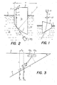
- Figure 1 is a schematic view of the first embodiment.
- Figure 2 is a schematic view of the second embodiment.
- Figure 3 is an enlarged partial view of this embodiment.
- This refractometer comprises a prism P placed on the path of a light beam coming from a light source S and passing through a lens LE.
- This prism P is partially immersed in a liquid L for which it is desired to measure the refractive index.
- the incidence and emergence faces of the * prism P form non-right angles with the axis of the light beam F, so that this beam undergoes a first refraction on entering the prism P and a second coming out.
- the variation in refractive index as a function of the temperature is very significantly lower than that of the liquid to be measured. If the temperature rises, for example, the angle of refraction of the incident beam increases less than the angle of refraction of the beam emerging from the prism, as shown in long lines in Figure 1. It follows that by correctly choosing the dimensions , the beams refracted at different temperatures meet at about a given point. These conditions will be examined in more detail in the case of the second embodiment.
- the refractometer illustrated in FIG. 2 comprises a prism P, one semi-cylindrical face 1 of which receives incident rays ri of a light beam coming from a light-emitting diode LED. This diode and the semi-cylindrical face 1 of the prism P are immersed in the liquid L for which it is desired to measure the refractive index.
- This prism has an emergence face 2 of the rays of the refracted incident beam which forms an angle ⁇ with a plane of convergence 3 of the refracted rays, parallel to a diametral plane of the semi-cylindrical face 1, receiving the incident rays, perpendicular to the general direction of the refracted rays rr through the prism P.
- a part of the incident rays ri are refracted through the prism P according to the ratio between the refraction index of the liquid ni and that of the prism n p forming on the plane of convergence 3 an unlit area u and an illuminated area s.
- term 1 of the equation is due to the thermal expansion of the prism and the values indicated are relative to the center of the ray for a photodiode independent of the prism. If the photodiode is fixed at a distance u directly on the prism P, it moves with the prism and there remains only a secondary error less than the indicated error, which can therefore be neglected.
- TPX with its highest dn / dt is the material which produces the smallest variation as a function of temperature, it does not allow this variation to be eliminated.
- the object of the invention mainly resides in a modification of the structure of the prism which consists in forming the angle e between the emergence face 2 of the prism P and the convergence plane 3 on which is range the graduation which, in this example, relates to the state of charge of the battery.
- an incident ray ri refracted through the prism has been shown and, after refraction, this ray is designated by rr. This corresponds to refraction at a first temperature T o . If the temperature rises from T o to T 1 , this same incident ray takes the path drawn in phantom lines rr 1 due to the decrease in the refractive index of the liquid.
- the sine of the angle ⁇ formed by the ray emerges with the normal to face 2 at the point of incidence of the ray on this face is a function of this index multiplied by the sine of the angle of incidence, so that the angle of refraction ⁇ decreases with increasing temperature, since the value of the incidence of refraction decreases when The temperature increases.
- This value is obtained by placing a double photodiode on the focal plane 3 of the refracted rays and by measuring the ratio R between the currents of PDa / PDb photodiodes as a function of the temperature of an H 2 SO 4 solution of refractive index 1 , 3680.
- the means do measured reports gives which is equivalent to an apparent variation in refractive index as a function of the temperature of -1.3.10- 5 / ° C.
- Table II gives the sensitivity of this TPX prism measured at different refractive indices of the liquid using a double photodiode PD a , PD b whose current is measured in nA, the current of the light-emitting diode LED being 50 mA.
- the angle ⁇ of this face 2 with the plane parallel to the diametral plane of the prism perpendicular to the general direction of the rays refracted through the prism being chosen at 35 °, we will calculate the position of the photodiode or of the scale graduated by ratio to the point of emergence on the cut side 2 of the refracted ray characteristic of the refractive index of the liquid and forming the transition line between the illuminated and non-illuminated areas.
- the prism of FIG. 1 has been partially represented on an enlarged scale. Its focusing plane 3 is partially cut to form the inclined face 2 of the angle ⁇ relative to the focusing plane 3. There are shown two refracted rays rr l and rr 2 which are characteristic of the refractive index of the liquid to 20 ° C and 30 ° C respectively. The distance d between these two refracted rays is very exaggerated to facilitate the explanation.
- the variation in refraction index of the prism P in TPX as a function of the temperature is, according to table I of 0.52.10 -4 / ° C which gives for a prism, whose radius r is 24.8 mm, a displacement d of 0.87 ⁇ m / ° C or 8.7 ⁇ m for 10 ° C.
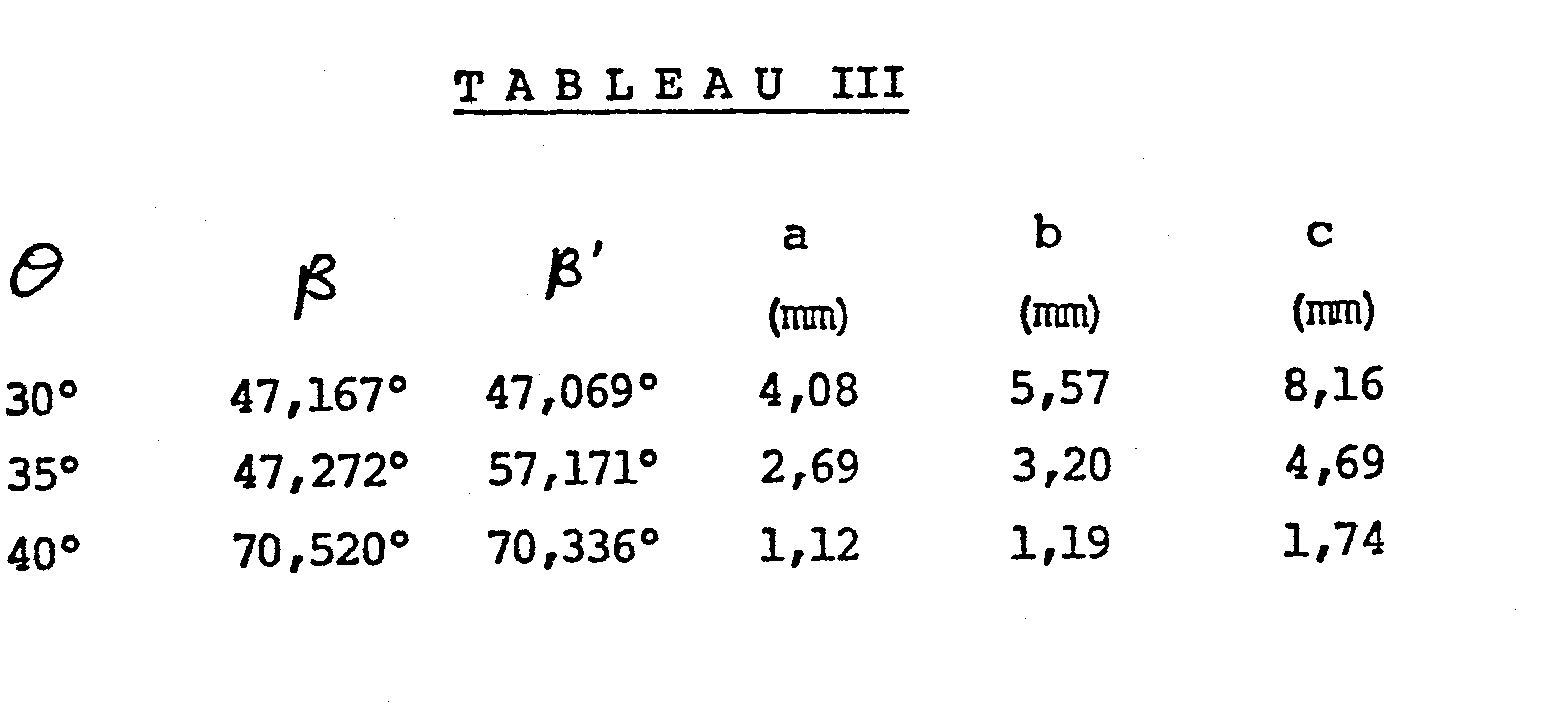
- the radius r being chosen as well as the angie ⁇ , d for a variation of 10 ° C being determined, it is necessary to calculate the parameters a, b and c to determine the position of the double photodiode PD a , PD b intended to measure the position of the transition line between the illuminated and unlit areas characteristic of the refractive index of the liquid in which the refractometer is immersed. This position is located in a zone of convergence of the rays emerging from the face 2 of the prism for a liquid of given concentration, but whose index is measured at different temperatures.
- Table III gives the values of these parameters, as well as the angles of refraction ⁇ , ⁇ 'respectively of the rays refracted through the prism rr 1 and rr2, this for different angles ⁇ of the face 2.
Abstract
Description
La présente invention a pour objet un réfractomètre pour mesurer l'indice de réfraction d'un liquide conprenant un prisme dont une des faces au mins est en contact avec le liquide à mesurer, une source de lumière pour diriger un faisceau de lumière à travers ce prisme et passant à travers ladite face en contact avec le liquide et à travers une face en contact avec un autre milieu.The subject of the present invention is a refractometer for measuring the refractive index of a liquid comprising a prism one of the faces of which at least is in contact with the liquid to be measured, a light source for directing a beam of light through this prism and passing through said face in contact with the liquid and through a face in contact with another medium.
De tels réfractomètres sont bien connus. Ils présentent généralement la particularité de mesurer l'indice de réfraction pour une température déterminée. Si cette particularité est acceptable lorsque la température du liquide peut être contrôlée, elle ne l'est pas dans d'autres cas comme les réfractonètres, utilisés pour indiquer l'état de charge d'une batterie en fonction de l'indice de réfraction de l'électrolyte de la batterie.Such refractometers are well known. They generally have the particularity of measuring the refractive index for a determined temperature. If this feature is acceptable when the temperature of the liquid can be controlled, it is not in other cases such as refractoneters, used to indicate the state of charge of a battery according to the refractive index of the battery electrolyte.
On a déjà décrit dans le brevet GB 2 008 793 un tel réfractomètre présentant une face formée d'une portion cylindrique réceptrice d'un faisceau de lumière incidente en contact avec ledit liquide et une face d'émergence des rayons lumineux réfractés par la face réceptrice et transmis à travers le prisme en formant le long de la face d'émergence de part et d'autre d'une ligne de transition, une zone éclairée et non éclairée, la position de cette ligne de transition étant fonction de l'indice de réfraction du liquide.
Comme expliqué dans Cptica acta 1970, vol. 17, No 5, pp. 363-380, il est possible, grâce à un prisme dont une surface réceptrice d'un faisceau lumineux est constituée par une portion de cylindre imnergée dans le liquide dont on veut connaître l'indice de réfraction, d'obtenir sur une face d'où émergent les rayons lumineux, une ligne de transition nette entre une zone éclairée, formée par la partie réfractée du faisceau traversant les deux milieux d'indice de réfraction différents et une zone non éclairée. Cette face où convergent les rayons lumineux se situe sur un plan parallèle à un diamètre du cylindre perpendiculaire à la direction générale des rayons réfractés et la position de la ligne de transition entre ces zones éclairées et non éclairées est une fonction pratiquement linéaire de l'indice de réfraction du liquide. Ce réfractomètre est basé sur le fait que l'angle d'incidence des rayons du faisceau lumineux augmente progressivement, en raison de la courbure de la surface réceptrice, de sorte qu'au-delà d'un angle critique, les rayons du faisceau lumineux ne sont plus réfractés à travers le prisme, cet angle critique d'incidence étant en fonction du rapport entre l'indice de réfraction du liquide et celui du prisme.As explained in Cptica acta 1970, vol. 17, No 5, pp. 363-380, it is possible, thanks to a prism of which a surface receiving a light beam is constituted by a portion of cylinder immersed in the liquid of which one wants to know the refractive index, to obtain on a face of where the light rays emerge, a clear transition line between an illuminated area, formed by the refracted part of the beam passing through the two media of different refractive index and an unlit area. This face where the light rays converge is located on a plane parallel to a diameter of the cylinder perpendicular to the general direction of the refracted rays and the position of the transition line between these lit and unlit areas is a function practically linear of the refractive index of the liquid. This refractometer is based on the fact that the angle of incidence of the rays of the light beam gradually increases, due to the curvature of the receiving surface, so that beyond a critical angle, the rays of the light beam are no longer refracted through the prism, this critical angle of incidence being a function of the ratio between the refractive index of the liquid and that of the prism.
Tous les rayons réfractés arrivent sur le plan de convergence à la droite d'un certain point qui forme la frontière entre les zones éclairées et non éclairées et la position de la ligne de contraste entre ces zones est fonction du rapport entre les indices de réfraction du liquide et celui de la sonde.All the refracted rays arrive on the plane of convergence to the right of a certain point which forms the border between the illuminated and non-illuminated zones and the position of the line of contrast between these zones is a function of the ratio between the refractive indices of the liquid and that of the probe.
Ces considérations sont vraies pour autant que la température du liquide et du prisme soit connue, ou demeure constante. Or, lorsque l'on utilise un tel réfractomètre pour déterminer l'indice de -réfraction de l'électrolyte d'une batterie électro-chimique et par là le degré de charge de cette batterie, on ne connaît pas la température de l'électrolyte qui peut varier de plusieurs dizaines de degrés lorsqu'il s'agit d'une batterie de voiture autanobi- le. Par conséquent, il n'est pas possible d'établir une corrélation directe entre l'indice de réfraction mesuré et l'état de charge de la batterie.These considerations are true as long as the temperature of the liquid and the prism is known, or remains constant. However, when using such a refractometer to determine the refractive index of the electrolyte of an electrochemical battery and thereby the degree of charge of this battery, the temperature of the electrolyte is not known. which can vary by several tens of degrees in the case of an autanobic car battery. Consequently, it is not possible to establish a direct correlation between the refractive index measured and the state of charge of the battery.
On connaît déjà des réfractomètres avec des moyens prévus en vue de compenser les variations de température, de manière à mesurer l'indice d'un liquide en fonction d'une température de référence.Refractometers are already known with means provided to compensate for temperature variations, so as to measure the index of a liquid as a function of a reference temperature.
De tels dispositifs font notamment l'objet du FR-A-2.159.771 ou du US-A-3.625.620. Dans ces deux solutions, on a recours à un mécanisme de correction utilisant un bilame de conpensation. Aussi simple que soit un tel mécanisme, son existence entraîne des complications, suppose un réglage préalable et est sensible à des vibrations.Such devices are in particular the subject of FR-A-2,159,771 or US-A-3,625,620. In these two solutions, use is made of a correction mechanism using a bimetallic strip of compensation. As simple as such a mechanism is, its existence leads to complications, supposes a preliminary adjustment and is sensitive to vibrations.
Le but de la présente invention est d'apporter une solution sensiblement exempte des inconvénients susmentionnés.The object of the present invention is to provide a solution which is substantially free from the abovementioned drawbacks.
A cet effet, la présente invention a pour objet un réfractomètre tel que défini par la revendication 1.To this end, the present invention relates to a refractometer as defined by claim 1.
L'avantage d'un tel réfractomètre est de fournir non seulement une indication linéaire en fonction de l'indice de réfraction, mais en plus une indication de cet indice ramené à une température de référence. Par conséquent, dans le cas où le liquide est constitué par l'électrolyte d'une batterie électro-chimique, cet indice de réfaction est une corrélation directe de l'état de charge de la batterie, dans la mesure où le paramètre température est pratiquement neutralisé ou tout au moins fortement atténué. La solution proposée est simple, entièrement optique et insensible aux vibrations, ce qui est particulièrement important dans le cas de son utilisation dans le domaine de l'automobile.The advantage of such a refractometer is to provide not only a linear indication as a function of the refractive index, but in addition an indication of this index reduced to a reference temperature. Consequently, in the case where the liquid consists of the electrolyte of an electro-chemical battery, this index of refraction is a direct correlation of the state of charge of the battery, insofar as the temperature parameter is practically neutralized or at least strongly attenuated. The proposed solution is simple, fully optical and insensitive to vibrations, which is particularly important in the case of its use in the automotive field.
Le dessin annexé illustre schématiquement et à titre d'exemple deux formes d'exécution du réfractomètre objet de la présente invention.The accompanying drawing illustrates schematically and by way of example two embodiments of the refractometer object of the present invention.
La figure 1 est une vue schématique de la première forme d'exécution.Figure 1 is a schematic view of the first embodiment.
La. figure 2 est une vue schématique de la seconde forme d'exécution.Figure 2 is a schematic view of the second embodiment.
La figure 3 est une vue partielle agrandie de cette forme d'exécution.Figure 3 is an enlarged partial view of this embodiment.
La forme d'exécution illustrée par la figure 1 est plus particulièrement destinée à expliquer le principe de la présente invention. Ce réfractomètre comporte un prisme P placé sur la trajectoire d'un faisceau lumineux issu d'une source lumineuse S et passant à travers une lentille LE. Ce prisme P est partiellement plongé dans un liquide L dont on désire mesurer l'indice de réfraction.The embodiment illustrated in Figure 1 is more particularly intended to explain the principle of the present invention. This refractometer comprises a prism P placed on the path of a light beam coming from a light source S and passing through a lens LE. This prism P is partially immersed in a liquid L for which it is desired to measure the refractive index.
Comme on le constate, les faces d'incidence et d'émergence du* prisme P forment des angles non droits avec l'axe du faisceau lumineux F, de sorte que ce faisceau subit une première réfraction en pénétrant dans le prisme P et une deuxième en en ressortant. Dans le cas présent où le milieu incident est de l'air, la variation d'indice de réfraction en fonction de la température est très sensiblement plus faible que celle du liquide à mesurer. Si la température augmente par exemple, l'angle de réfraction du faisceau incident augmente moins que l'angle de réfraction du faisceau émergent du prisme, comme illustrée en traits interronpus à la figure 1. Il s'ensuit qu'en choisissant correctement les dimensions, les faisceaux réfractés à des températures différentes se rejoignent à peu près en un point donné. Ces conditions seront examinées plus en détail dans le cas de la seconde forme d'exécution.As can be seen, the incidence and emergence faces of the * prism P form non-right angles with the axis of the light beam F, so that this beam undergoes a first refraction on entering the prism P and a second coming out. In the present case where the incident medium is air, the variation in refractive index as a function of the temperature is very significantly lower than that of the liquid to be measured. If the temperature rises, for example, the angle of refraction of the incident beam increases less than the angle of refraction of the beam emerging from the prism, as shown in long lines in Figure 1. It follows that by correctly choosing the dimensions , the beams refracted at different temperatures meet at about a given point. These conditions will be examined in more detail in the case of the second embodiment.
Le réfractomètre illustré par la figure 2 conporte un prisme P dont une face semi-cylindrique 1, reçoit des rayons incidents ri d'un faisceau lumineux issu d'un diode électroluminescente DEL. Cette diode et la face semi-cylindrique 1 du prisme P sont plongées dans le liquide L dont on désire mesurer l'indice de réfraction. Ce prisme comporte une face d'émergence 2 des rayons du faisceau incident réfractés qui forme un angle θ avec un plan de convergence 3 des rayons réfractés, parallèle à un plan diamétral de la face semi-cylindrique 1, réceptrice des rayons incidents, perpendiculaire à la direction générale des rayons réfractés rr à travers le prisme P. Une partie des rayons incidents ri sont réfractés à travers le prisme P en fonction du rapport entre l'indice de réfraction du liquide ni et celui du prisme np en formant sur le plan de convergence 3 une zone non éclairée u et une zone éclairée s.The refractometer illustrated in FIG. 2 comprises a prism P, one semi-cylindrical face 1 of which receives incident rays ri of a light beam coming from a light-emitting diode LED. This diode and the semi-cylindrical face 1 of the prism P are immersed in the liquid L for which it is desired to measure the refractive index. This prism has an
Nous allons examiner maintenant comment la longueur de la zone non éclairée u varie en fonction de la température, r étant le rayon de la face semi-cylindrique 1,We will now examine how the length of the unlit area u varies as a function of temperature, r being the radius of the semi-cylindrical face 1,

Examinons maintenant l'influence de la variation d'indice de réfraction du prisme en fonction de la température pour un prisme dont la face d'émergence 2 forme un angle nul avec le plan 3, pour un prisme en plexiglas (RMMA) ainsi que pour un prisme en palymé- thyl pentane (TPX), tous deux avec la face réceptrice 1 plongée dans une solution de H2S04 à 28 %.Let us now examine the influence of the variation in refractive index of the prism as a function of temperature for a prism whose

-
Le terme 1 de l'équation de

-
Le terme 2 de l'équation de

Term 2 of the equation of -
Le terme 3 de l'équation de


Term 3 of the equation of

![]()
![]()
![]()
![]()
![]()
![]()
On constate que u varie d'autant moins que la variation d'indice de réfraction du prisme en fonction de la température est de valeur plus grande.It can be seen that u varies the less the greater the variation in refractive index of the prism as a function of the temperature.
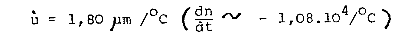
Il y a lieu de remarquer que le terme 1 de l'équation est dû à la dilatation thermique du prisme et les valeurs indiquées sont relatives au centre du rayon pour une photodiode indépendante du prisme. Si la photodiode est fixée à une distance u directement sur le prisme P, elle se déplace avec le prisme et il ne subsiste qu'une erreur secondaire inférieure à l'erreur indiquée, qui peut de ce fait être négligée.It should be noted that term 1 of the equation is due to the thermal expansion of the prism and the values indicated are relative to the center of the ray for a photodiode independent of the prism. If the photodiode is fixed at a distance u directly on the prism P, it moves with the prism and there remains only a secondary error less than the indicated error, which can therefore be neglected.
Le tableau I qui va suivre conpare la sensibilité en température de différentes matières plastiques.

- 1. Mesuré sur réfractomètre Abbé n et dn/dT
- 2. Mesuré dans un milieu d'indice de réfraction de 1,38 en utilisant un microscope avec une graduation pour observer le déplacement de la ligne de transition noir/clair
- 3. Avec double PD BPx48 collée sur le prisme
- 4. De Polymer Handbook, et "Plastics Optics" Optical Spectra, Juillet 1974, p. 27.
- 1. Measured on Abbé n and dn / dT refractometer
- 2. Measured in a medium with a refractive index of 1.38 using a microscope with a graduation to observe the displacement of the black / clear transition line
- 3. With double PD BPx48 bonded to the prism
- 4. De Polymer Handbook, and "Plastics Optics" Optical Spectra, July 1974, p. 27.
Si le TPX avec son dn/dt le plus élevé est le matériau qui produit la variation la plus faible en fonction de la température, il ne permet pas d'éliminer cette variation.If the TPX with its highest dn / dt is the material which produces the smallest variation as a function of temperature, it does not allow this variation to be eliminated.
C'est la raison pour laquelle l'objet de l'invention réside principalement dans une modification de structure du prisme qui consiste à former l'angle e entre la face d'émergence 2 du prisme P et le plan de convergence 3 sur lequel est portée la graduation qui, dans cet exemple, est relative à l'état de charge de la batterie.This is the reason why the object of the invention mainly resides in a modification of the structure of the prism which consists in forming the angle e between the
Si l'on se reporte au schéma explicatif de la figure 1, on a représenté un rayon incident ri réfracté à travers le prisme et, après réfraction, ce rayon est désigné par rr. Ceci correspond à la réfraction à une première tenpérature To. Si la température s'élève de To à T1, ce même rayon incident prend la trajectoire dessinée en traits mixtes rr1 du fait de la diminution de l'indice de réfraction du liquide. Etant donné qu'il y a également diminution de l'indice de réfraction du matériau formant le prisme P, le sinus de l'angle β que forme le rayon émergent avec la normale à la face 2 au point d'incidence du rayon sur cette face, est fonction de cet indice multiplié par le sinus de l'angle d'incidence, de sorte que l'angle de réfraction β diminue avec l'augmentation de la température, du fait que la valeur de l'incidence de réfraction diminue lorsque la température augmente.If we refer to the explanatory diagram of FIG. 1, an incident ray ri refracted through the prism has been shown and, after refraction, this ray is designated by rr. This corresponds to refraction at a first temperature T o . If the temperature rises from T o to T 1 , this same incident ray takes the path drawn in phantom lines rr 1 due to the decrease in the refractive index of the liquid. Since there is also a decrease in the refractive index of the material forming the prism P, the sine of the angle β formed by the ray emerges with the normal to face 2 at the point of incidence of the ray on this face, is a function of this index multiplied by the sine of the angle of incidence, so that the angle of refraction β decreases with increasing temperature, since the value of the incidence of refraction decreases when The temperature increases.
Cette compensation n'est pas totale. Toutefois, on constate que le prisme en TPX, dont la valeur dn/dT mesurée (voir tableau I) est de -0,66.10-4/°C, passe avec le prisme dont la face 2 fait un angle θ de 35° avec le plan 3, à -1,3.10-5/°C.This compensation is not total. However, we note that the TPX prism, whose measured dn / dT value (see Table I) is -0.66.10 -4 / ° C, passes with the prism whose
Cette valeur est obtenue en plaçant une double photodiode sur le plan focal 3 des rayons réfractés et en mesurant le rapport R entre les courants de photodiodes PDa/PDb en fonction de la température d'une solution H2SO4 d'indice de réfraction 1,3680. La moyenne des rapports mesurés donne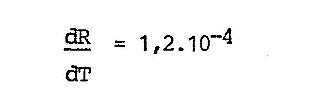
Le tableau II donne la sensibilité de ce prisme en TPX mesurée à différents indices de réfraction du liquide à l'aide d'une double photodiode PDa, PDb dont le courant est mesuré en nA, le courant de la diode électroluminescente DEL étant de 50 mA.

La sensibilité ![]()
![]()
L'angle θ de cette face 2 avec le plan parallèle au plan diamétral du prisme perpendiculaire à la direction générale des rayons réfractés à travers le prisme étant choisi à 35°, nous allons calculer la position de la photodiode ou de l'échelle graduée par rapport au point d'émergence sur la face coupée 2 du rayon réfracté caractéristique de l'indice de réfraction du liquide et formant la ligne de transition entre les zones éclairées et non éclairées.The angle θ of this
Si l'on se reporte à la figure 2, on a représenté partiellement le prisme de la figure 1 à échelle agrandie. Son plan de focalisation 3 est partiellement coupé pour former la face 2 inclinée de l'angle θ par rapport au plan de focalisation 3. On a représenté deux rayons réfractés rrl et rr2 qui sont caractéristiques de l'indice de réfraction du liquide à respectivement 20°C et 30°C. La distance d entre ces deux rayons réfractés est très fortement exagérée pour faciliter l'explication. La variation d'indice de réfraction du prisme P en TPX en fonction de la température est, selon le tableu I de 0,52.10-4/°C ce qui donne pour un prisme, dont le rayon r est de 24,8 mm, un déplacement d de 0,87µm/°C ou 8,7µm pour 10°C.Referring to FIG. 2, the prism of FIG. 1 has been partially represented on an enlarged scale. Its focusing
Le rayon r étant choisi de même que l' angie θ , d pour une variation de 10°C étant déterminé, il y a lieu de calculer les paramètres a, b et c pour déterminer la position de la double photodiode PDa, PDb destinée à mesurer la position de la ligne de transition entre les zones éclairées et non éclairées caractéristique de l'indice de réfraction du liquide dans lequel le réfractomètre est plongé. Cette position se situe dans une zone de convergence des rayons émergents de la face 2 du prisme pour un liquide de concentration donnée, mais dont l'indice est mesuré à différentes températures.

![]()

![]()
Le tableau III donne les valeurs de ces paramètres, ainsi que des angles de réfraction β , β' respectivement des rayons réfractés à travers le prisme rr1 et rr2, ceci pour différents angles θ de la face 2.
Claims (3)
Priority Applications (1)
| Application Number | Priority Date | Filing Date | Title |
|---|---|---|---|
| AT84810376T ATE38900T1 (en) | 1983-08-03 | 1984-07-31 | REFRACTOMETER FOR MEASURING THE REFERENCE INDEX OF A LIQUID. |
Applications Claiming Priority (2)
| Application Number | Priority Date | Filing Date | Title |
|---|---|---|---|
| CH4215/83 | 1983-08-03 | ||
| CH421583 | 1983-08-03 |
Publications (2)
| Publication Number | Publication Date |
|---|---|
| EP0133607A1 true EP0133607A1 (en) | 1985-02-27 |
| EP0133607B1 EP0133607B1 (en) | 1988-11-23 |
Family
ID=4271939
Family Applications (1)
| Application Number | Title | Priority Date | Filing Date |
|---|---|---|---|
| EP84810376A Expired EP0133607B1 (en) | 1983-08-03 | 1984-07-31 | Refractometer for the measurement of the refractive index of a liquid |
Country Status (6)
| Country | Link |
|---|---|
| US (1) | US4682889A (en) |
| EP (1) | EP0133607B1 (en) |
| JP (1) | JPS60501969A (en) |
| AT (1) | ATE38900T1 (en) |
| DE (1) | DE3475347D1 (en) |
| WO (1) | WO1985000886A1 (en) |
Cited By (1)
| Publication number | Priority date | Publication date | Assignee | Title |
|---|---|---|---|---|
| CN108478044A (en) * | 2018-05-29 | 2018-09-04 | 莆田市烛火信息技术有限公司 | A kind of brine for kitchen use, syrup concentration regulate and control Intelligent water cup |
Families Citing this family (7)
| Publication number | Priority date | Publication date | Assignee | Title |
|---|---|---|---|---|
| US5870185A (en) * | 1996-10-21 | 1999-02-09 | C.F.C. Technology, Inc. | Apparatus and method for fluid analysis |
| US20090139318A1 (en) * | 2007-12-04 | 2009-06-04 | Caterpillar Inc. | Systems and methods for monitoring the quality of a reducing agent |
| US8411262B2 (en) | 2010-09-30 | 2013-04-02 | Precision Energy Services, Inc. | Downhole gas breakout sensor |
| US8542353B2 (en) | 2010-09-30 | 2013-09-24 | Precision Energy Services, Inc. | Refractive index sensor for fluid analysis |
| FI127243B (en) * | 2014-05-13 | 2018-02-15 | Janesko Oy | Method and measuring device for continuous measurement of Abbe number |
| KR102101434B1 (en) * | 2018-02-22 | 2020-04-16 | 광운대학교 산학협력단 | Optical Refractometer and real time monitoring analysis device having the same |
| US11708760B2 (en) | 2019-03-12 | 2023-07-25 | Baker Hughes Oilfield Operations Llc | Immersed lens downhole refractometer |
Citations (4)
| Publication number | Priority date | Publication date | Assignee | Title |
|---|---|---|---|---|
| US3267795A (en) * | 1961-02-20 | 1966-08-23 | American Optical Corp | Temperature compensated refractometers |
| US3625620A (en) * | 1970-08-24 | 1971-12-07 | American Optical Corp | Refractometer |
| FR2159771A5 (en) * | 1971-11-12 | 1973-06-22 | Sopelem | |
| GB2008793A (en) * | 1977-11-04 | 1979-06-06 | Anacon Instr Ltd | Refractometers |
Family Cites Families (14)
| Publication number | Priority date | Publication date | Assignee | Title |
|---|---|---|---|---|
| US2319889A (en) * | 1941-07-05 | 1943-05-25 | Bausch & Lomb | Refractometer |
| NL89367C (en) * | 1944-05-26 | |||
| US2427996A (en) * | 1944-09-28 | 1947-09-23 | American Cyanamid Co | Temperature compensator for refractometers |
| US2421854A (en) * | 1944-09-28 | 1947-06-10 | American Cyanamid Co | Temperature compensator for refractometers |
| GB1209036A (en) * | 1967-06-19 | 1970-10-14 | Nat Res Dev | Improvements in or relating to refractometers |
| GB1252766A (en) * | 1968-11-26 | 1971-11-10 | ||
| FR2250434A7 (en) * | 1973-11-07 | 1975-05-30 | Merkel Fritz | Manual refractometer accessory device - has constant light source and large volume of liquid to ensure accuracy and reproducibility |
| DE2860995D1 (en) * | 1977-07-01 | 1981-11-26 | Battelle Memorial Institute | Device for generating a light signal characteristic of the refractive index of a fluidand and its use |
| US4240747A (en) * | 1979-10-03 | 1980-12-23 | Battelle Memorial Institute | Refractive-index responsive light-signal system |
| CH652825A5 (en) * | 1980-09-18 | 1985-11-29 | Battelle Memorial Institute | DUAL OPTICAL PROBE DEVICE FOR DETERMINING THE REFRACTION INDEX OF A FLUID RETURNED TO A PREDETERMINED REFERENCE TEMPERATURE. |
| CH640056A5 (en) * | 1981-01-30 | 1983-12-15 | Battelle Memorial Institute | DEVICE FOR DETERMINING THE REFRACTION INDEX OF A FLUID RETURNED TO A REFERENCE TEMPERATURE. |
| US4427913A (en) * | 1981-06-01 | 1984-01-24 | The United States Of America As Represented By The Secretary Of The Army | Acoustic diffractometer |
| US4539475A (en) * | 1983-03-14 | 1985-09-03 | Pitney Bowes Inc. | Temperature compensation system for a prism in an optical transducer |
| GB2136593A (en) * | 1983-03-14 | 1984-09-19 | Ford Motor Co | Apparatus for detecting changes in density of light transmitting liquids |
-
1984
- 1984-07-31 EP EP84810376A patent/EP0133607B1/en not_active Expired
- 1984-07-31 US US06/720,411 patent/US4682889A/en not_active Expired - Fee Related
- 1984-07-31 WO PCT/CH1984/000122 patent/WO1985000886A1/en unknown
- 1984-07-31 AT AT84810376T patent/ATE38900T1/en not_active IP Right Cessation
- 1984-07-31 DE DE8484810376T patent/DE3475347D1/en not_active Expired
- 1984-07-31 JP JP59502870A patent/JPS60501969A/en active Granted
Patent Citations (4)
| Publication number | Priority date | Publication date | Assignee | Title |
|---|---|---|---|---|
| US3267795A (en) * | 1961-02-20 | 1966-08-23 | American Optical Corp | Temperature compensated refractometers |
| US3625620A (en) * | 1970-08-24 | 1971-12-07 | American Optical Corp | Refractometer |
| FR2159771A5 (en) * | 1971-11-12 | 1973-06-22 | Sopelem | |
| GB2008793A (en) * | 1977-11-04 | 1979-06-06 | Anacon Instr Ltd | Refractometers |
Non-Patent Citations (1)
| Title |
|---|
| OPTICA ACTA, vol. 17, no. 5, 1970, pages 363-380, Londres, GB; J.E. GEAKE: "Optical properties of the linear critical-angle refractometer" * |
Cited By (2)
| Publication number | Priority date | Publication date | Assignee | Title |
|---|---|---|---|---|
| CN108478044A (en) * | 2018-05-29 | 2018-09-04 | 莆田市烛火信息技术有限公司 | A kind of brine for kitchen use, syrup concentration regulate and control Intelligent water cup |
| CN108478044B (en) * | 2018-05-29 | 2019-11-26 | 杨荣华 | A kind of salt water for kitchen use, syrup concentration regulate and control Intelligent water cup |
Also Published As
| Publication number | Publication date |
|---|---|
| ATE38900T1 (en) | 1988-12-15 |
| JPH0262183B2 (en) | 1990-12-25 |
| WO1985000886A1 (en) | 1985-02-28 |
| DE3475347D1 (en) | 1988-12-29 |
| US4682889A (en) | 1987-07-28 |
| EP0133607B1 (en) | 1988-11-23 |
| JPS60501969A (en) | 1985-11-14 |
Similar Documents
| Publication | Publication Date | Title |
|---|---|---|
| US4952055A (en) | Differential refractometer | |
| EP1910805B1 (en) | Optical refractometer for measuring seawater salinity and corresponding salinity sensor | |
| EP0094864A1 (en) | Process and device for the simultaneous measurement of geometrical characteristics of an optical fibre | |
| US5017008A (en) | Particle measuring apparatus | |
| FR2581206A1 (en) | OPTICAL FIBER OPTIC TRANSDUCER | |
| JPS633255B2 (en) | ||
| EP0453226A2 (en) | Fiber optic liquid leak detector | |
| EP0133607B1 (en) | Refractometer for the measurement of the refractive index of a liquid | |
| KR940003737B1 (en) | Fibre optic liquid level gauge | |
| EP0057667B1 (en) | Device for the measurement of the refraction index of a fluid | |
| EP0263016B1 (en) | Displacement and proximity detector with three optical fibres | |
| CA2136583A1 (en) | Device for detecting light diffused by colloidal thin films | |
| EP0562911B1 (en) | Method for the relative measurement of the axis of an opening and of the axis of a cylindrical contour | |
| FR2542878A1 (en) | SCANNING DEVICE | |
| FR2700006A1 (en) | Index profile measuring apparatus of an optical fiber preform having an outer envelope and a heart. | |
| WO2010076540A1 (en) | Optical fibre device for interferometric analysis of the surface condition of an object | |
| US5220180A (en) | Fiber optic fuel and liquid gauge having an open rigid "J" shaped tube | |
| FR2792066A1 (en) | DEVICE FOR DIMENSIONAL MEASUREMENT AND FAULT CONTROL OF OPTICAL FIBERS IN PRODUCTION | |
| EP0591912B1 (en) | Interferometer, comprising an intergrated arrangement and a mirror, which are seperated from each other by a measurement zone | |
| Danisch | Removing index of refraction constraints in the optical measurement of liquid level | |
| JPH044167Y2 (en) | ||
| Russo et al. | Liquid refractometry: an approach for a continuous measurement | |
| JPS59162427A (en) | Optical temperature sensor | |
| EP2271912A1 (en) | Optical probe for determining quantities of a two-phase flow | |
| FR2580388A1 (en) | Fibre optic dimension sensor |
Legal Events
| Date | Code | Title | Description |
|---|---|---|---|
| PUAI | Public reference made under article 153(3) epc to a published international application that has entered the european phase |
Free format text: ORIGINAL CODE: 0009012 |
|
| AK | Designated contracting states |
Designated state(s): AT BE CH DE FR GB IT LI LU NL SE |
|
| 17P | Request for examination filed |
Effective date: 19850624 |
|
| RAP1 | Party data changed (applicant data changed or rights of an application transferred) |
Owner name: STANLEY ELECTRIC CO., LTD. |
|
| 17Q | First examination report despatched |
Effective date: 19861205 |
|
| D17Q | First examination report despatched (deleted) | ||
| GRAA | (expected) grant |
Free format text: ORIGINAL CODE: 0009210 |
|
| AK | Designated contracting states |
Kind code of ref document: B1 Designated state(s): AT BE CH DE FR GB IT LI LU NL SE |
|
| REF | Corresponds to: |
Ref document number: 38900 Country of ref document: AT Date of ref document: 19881215 Kind code of ref document: T |
|
| REF | Corresponds to: |
Ref document number: 3475347 Country of ref document: DE Date of ref document: 19881229 |
|
| ITF | It: translation for a ep patent filed |
Owner name: MODIANO & ASSOCIATI S.R.L. |
|
| GBT | Gb: translation of ep patent filed (gb section 77(6)(a)/1977) | ||
| PLBE | No opposition filed within time limit |
Free format text: ORIGINAL CODE: 0009261 |
|
| STAA | Information on the status of an ep patent application or granted ep patent |
Free format text: STATUS: NO OPPOSITION FILED WITHIN TIME LIMIT |
|
| 26N | No opposition filed | ||
| ITTA | It: last paid annual fee | ||
| PGFP | Annual fee paid to national office [announced via postgrant information from national office to epo] |
Ref country code: BE Payment date: 19930422 Year of fee payment: 10 |
|
| PGFP | Annual fee paid to national office [announced via postgrant information from national office to epo] |
Ref country code: AT Payment date: 19930527 Year of fee payment: 10 |
|
| PGFP | Annual fee paid to national office [announced via postgrant information from national office to epo] |
Ref country code: SE Payment date: 19930608 Year of fee payment: 10 |
|
| PGFP | Annual fee paid to national office [announced via postgrant information from national office to epo] |
Ref country code: LU Payment date: 19930609 Year of fee payment: 10 |
|
| PGFP | Annual fee paid to national office [announced via postgrant information from national office to epo] |
Ref country code: CH Payment date: 19930730 Year of fee payment: 10 |
|
| EPTA | Lu: last paid annual fee | ||
| PG25 | Lapsed in a contracting state [announced via postgrant information from national office to epo] |
Ref country code: LU Free format text: LAPSE BECAUSE OF NON-PAYMENT OF DUE FEES Effective date: 19940731 Ref country code: LI Effective date: 19940731 Ref country code: CH Effective date: 19940731 Ref country code: BE Effective date: 19940731 Ref country code: AT Effective date: 19940731 |
|
| PGFP | Annual fee paid to national office [announced via postgrant information from national office to epo] |
Ref country code: NL Payment date: 19940731 Year of fee payment: 11 |
|
| PG25 | Lapsed in a contracting state [announced via postgrant information from national office to epo] |
Ref country code: SE Effective date: 19940801 |
|
| BERE | Be: lapsed |
Owner name: STANLEY ELECTRIC CO. LTD Effective date: 19940731 |
|
| EAL | Se: european patent in force in sweden |
Ref document number: 84810376.8 |
|
| REG | Reference to a national code |
Ref country code: CH Ref legal event code: PL |
|
| EUG | Se: european patent has lapsed |
Ref document number: 84810376.8 |
|
| PG25 | Lapsed in a contracting state [announced via postgrant information from national office to epo] |
Ref country code: NL Effective date: 19960201 |
|
| NLV4 | Nl: lapsed or anulled due to non-payment of the annual fee |
Effective date: 19960201 |
|
| PGFP | Annual fee paid to national office [announced via postgrant information from national office to epo] |
Ref country code: GB Payment date: 19970722 Year of fee payment: 14 |
|
| PGFP | Annual fee paid to national office [announced via postgrant information from national office to epo] |
Ref country code: FR Payment date: 19970723 Year of fee payment: 14 |
|
| PGFP | Annual fee paid to national office [announced via postgrant information from national office to epo] |
Ref country code: DE Payment date: 19970731 Year of fee payment: 14 |
|
| PG25 | Lapsed in a contracting state [announced via postgrant information from national office to epo] |
Ref country code: GB Free format text: LAPSE BECAUSE OF NON-PAYMENT OF DUE FEES Effective date: 19980731 |
|
| GBPC | Gb: european patent ceased through non-payment of renewal fee |
Effective date: 19980731 |
|
| PG25 | Lapsed in a contracting state [announced via postgrant information from national office to epo] |
Ref country code: FR Free format text: LAPSE BECAUSE OF NON-PAYMENT OF DUE FEES Effective date: 19990331 |
|
| REG | Reference to a national code |
Ref country code: FR Ref legal event code: ST |
|
| PG25 | Lapsed in a contracting state [announced via postgrant information from national office to epo] |
Ref country code: DE Free format text: LAPSE BECAUSE OF NON-PAYMENT OF DUE FEES Effective date: 19990701 |