EP0133054B1 - Running toy - Google Patents
Running toy Download PDFInfo
- Publication number
- EP0133054B1 EP0133054B1 EP19840305220 EP84305220A EP0133054B1 EP 0133054 B1 EP0133054 B1 EP 0133054B1 EP 19840305220 EP19840305220 EP 19840305220 EP 84305220 A EP84305220 A EP 84305220A EP 0133054 B1 EP0133054 B1 EP 0133054B1
- Authority
- EP
- European Patent Office
- Prior art keywords
- gear
- moving portion
- timing gear
- wheels
- running
- Prior art date
- Legal status (The legal status is an assumption and is not a legal conclusion. Google has not performed a legal analysis and makes no representation as to the accuracy of the status listed.)
- Expired
Links
- 230000005540 biological transmission Effects 0.000 claims description 30
- 230000009191 jumping Effects 0.000 description 7
- 238000010276 construction Methods 0.000 description 5
- 230000000994 depressogenic effect Effects 0.000 description 2
- 238000013459 approach Methods 0.000 description 1
- 238000010009 beating Methods 0.000 description 1
- 230000015572 biosynthetic process Effects 0.000 description 1
- 230000000694 effects Effects 0.000 description 1
- 230000005484 gravity Effects 0.000 description 1
- 239000000463 material Substances 0.000 description 1
- 230000004048 modification Effects 0.000 description 1
- 238000012986 modification Methods 0.000 description 1
Images




Classifications
-
- A—HUMAN NECESSITIES
- A63—SPORTS; GAMES; AMUSEMENTS
- A63H—TOYS, e.g. TOPS, DOLLS, HOOPS OR BUILDING BLOCKS
- A63H17/00—Toy vehicles, e.g. with self-drive; ; Cranes, winches or the like; Accessories therefor
- A63H17/004—Stunt-cars, e.g. lifting front wheels, roll-over or invertible cars
Definitions
- This invention relates to a running toy which performs jumping or somersault operation.
- a running toy which performs a somersault operation has been disclosed by Japanese Patent Publication No. 54-16780.
- the running toy according to that patent of the present applicant has a swingable lever which at one of its ends is pivotally mounted in a body of the toy, with a weight at its opposite end disposed outside of the body.
- the lever In use the lever is pushed down against the force of a spring and restrained by a stopper.
- the toy is then pushed to run by hand and the resilient force which has been stored in the spring is released all at once when the toy has run a predetermined distance and the lever is released, whereby the toy jumps up above the path and somersaults.
- the running toy mentioned above might be suitable for relatively young children, but its operation would not be satisfactory for activity toys such as stunt car and motorcycle which attach importance to the ability of running after jumping.
- an object of the invention is to provide an improved running toy.
- a running toy comprising a housing having wheels for running and a downward facing inner surface, a moving portion disposed in said housing so as to move in the up and down directions and transfer its movement energy to the housing by impact with the inner surface, a spring which imparts an upward force to said moving portion, a stopper member which holds said moving portion at the position where it is pushed down against the resilient force of said spring, a timing gear driven by one of said wheels, and release means attached to said timing gear for releasing engagement between the moving portion and said stopper member when said timing gear is rotated by a predetermined amount, characterised by said moving portion comprising a weight which has a recess formed in a bottom surface thereof, and said spring is disposed in said recess so as to expand and contract in the up and down directions.
- the running toy includes a timing gear return mechanism for automatically returning said timing gear to a starting position.
- the running toy comprises an axle for said wheels and a worm gear fitted to the axle and engaging said timing gear, said release means comprising a cam provided in concentric relationship with the timing gear or a projection provided on a surface of the timing gear in an eccentric manner.
- axles of the wheels for running penetrate through elongated holes that are formed on both sides of the housing, the holes being elongated in the up and down directions, and when the housing is lifted up, the axles of wheels for running descend along the holes due to their own weight, whereby the worm gear fitted to the axle of the wheels, for running disengages from the timing gear.
- the moving portion includes a flywheel that rotatably drives the wheels for running
- the release means comprises a projection that releases the engagement between the moving portion and said stopper member when the timing gear is rotated to a predetermined position.
- the moving portion preferably includes a transmission gear which is positioned between a coaxial gear rotating with the wheels for running and the timing gear, and the timing gear comprises a deformable gear having a nondeformable part formed by a nondeformable curve with a curvature radius which is more than that of another, deformable part measured from the same center, the deformable part given flexibility by an arcuate slot opposite the nondeformable part, and having a cutout part formed at a position slightly distanced from a starting point of the arcuate slot, the cutout part facing the transmission gear when the moving portion abuts on the inner surface of the housing, said deformable gear meshing with the transmission gear when the moving portion is at the position where it is pushed down, and teeth at the starting point of the cutout part of the deformable gear meshing with the transmission gear when the projection comes to the position where it releases the restraint of said moving portion by the stopper member during rotation of the deformable gear.
- the transmission gear is preferably arranged to disengage from the coaxial gear and the timing gear by pushing a button projected outside of the body.
- Fig. 1 shows a toy car according to a preferred embodiment of the invention
- Figs. 2 and 3 show the internal construction thereof.
- the toy car has a housing 1 of the shape of the body of a passenger car, and front and rear pairs of wheels 3a and 3b attached to both ends of a front axle 2a and a rear axle 2b that penetrate through both side walls of the housing.
- To the front axle 2a is attached a worm gear 4 which meshes with a spur gearthatwill be mentioned later.
- Through holes 5 where the axles 2a, 2b rotatably penetrate have vertically elongated shapes formed in both side walls of the housing 1.
- the axles When the toy car is placed on the floor, the axles are positioned at the upper ends of the through holes 5 to support the housing 1 as shown in Fig. 3. When the toy car is lifted up, on the other hand, the axles descend to the lower ends of the through holes 5 due to their own weight and a weight of the wheels 3a and 3b.
- a moving portion or member 6 consisting of a weight having the shape of rectangular paral- lelopiped is disposed at a central position in the housing 1 so as to move in the upper and lower directions.
- a push button 9 is attached to the upper end of the shaft 8.
- a recess 6a of a circular shape in cross section is formed in the lower surface of the moving member 6 as shown in Fig. 3, and a coil spring 10 is accommodated to freely expand and contract therein.
- a nearly L-shaped stopper member 11 in the back and forth direction to hold the moving member 6 at a lower position against the resilient force of the spring 10 as shown in Fig. 2.
- the stopper member 11 is supported at its rear end 11 b by a pin 12 so as to rotate in the horizontal direction, and has a forwardly stretching portion of an inverted L-shape in cross section so as to come into engagement with the upper edge portion of the protuberance 7 on the upper surface of the moving member. Further, the front end of the stopper member 11 is downwardly bent, and its lower end 11 a is forwardly protruded.
- the stopper member 11 of the above-mentioned shape is pulled to turn in the counterclockwise direction as viewed from the upper side with the pin 12 as a center, by a spring 13 which is disposed between the bent portion of the stopper member 11 and a portion of the housing 1.
- the stopper member 11 comes into contact with the side surface of protuberance 7 on the moving member 6.
- the push button 9 is depressed by a finger against the force of the spring 10 to lower the moving member 6 and the protuberance 7, the stopper member 11 slightly turns in the counterclockwise direction, engages with the upper edge of the protuberance 7, and holds the moving member 6 at the lower position.
- a spur gear 14 is disposed to mesh with the worm gear 4 between the lower end 11 a of the stopper member 11 and the front axle 2a.
- An eccentric pin 15 is studded on the upper surface of the spur gear 14. When the pin 15 comes into engagement with the lower end 11 a of the stopper member 11 to push it in the clockwise direction, the moving member 6 is held no more at the lower position by the stopper member 11. To bring the pin 15 to a predetermined start position, furthermore, a spring 16 is connected between the pin 15 and a portion of the housing 1.
- the toy car of Fig. 1 operates as described below.
- Fig. 2 illustrates this condition.
- the worm gear 4 of the front axle 2a is in mesh with the spur gear 14, and the pin 15 is located at the starting position as shown. This is because, if the toy is once lifted up prior to placing it on a plane, the axle 2a descends to the lower end of through holes 5 of the housing 1, and the worm gear 4 disengages from the spur gear 14. Therefore, the spur gear 14 and the pin 15 are returned to the starting position being pulled by the spring 16.
- the toy car performs the jumping operation when it has run a predetermined distance, i.e., when the pin 15 is turned to a position at which the moving member 6 is no more held by the stopper member 11.
- the toy car can be constructed to perform somersault operation by changing the position of the moving member.
- Fig. 4 shows a toy car which performs somersault operation after it has run a predetermined distance according to modified embodiment of the invention.
- the construction of this embodiment is fundamentally the same as the toy of Fig. 1, but is different with respect to the points mentioned below.
- the direction in which the toy proceeds is opposite. That is, the worm gear 4 is attached to the axle 2b of the rear wheels 3b.
- the spur gear 14 rotates in the counterclockwise direction.
- a cam 17 is provided on the upper surface of the spur gear 14 in concentric therewith, and the protruded portion of the cam 17 comes into engagement with the lower end 11 a of the stopper member 11 to push it leftwards, so that the moving member 6 is no more held at the lower position by the stopper member 11.
- the spring 13 is hooked to the downwardly bent portion of the stopper member 11 to turn it in the counterclockwise direction.
- the moving member 6 has a columnar shape and is disposed in a front portion of the car body.
- the mechanism for liberating the moving member from the stopper member may be any one which operates being interlocked to the rotation of wheels, and need not be limited to the one which is shown in the drawings.
- Fig. 5 shows a toy motorcycle according to another preferred embodiment of the invention
- Fig. 6 is a sectional view along the line VI-VI, which shows the internal construction of the toy.
- the toy motorcycle comprises a hollow body 22 of the shape of a motorcycle, and front and rear wheels 28 and 30 which are rotatably attached to front and rear portions of the body by axles 24 and 26, respectively.
- a strip-like rubber tire 30a is wound around a rearwheel 30.
- Afront end of the body 22 has a through hole 34 (Fig. 7), through which an upper portion of a tilted handle shaft 32 penetrates loosely to move in upper and lower directions, and has an upper surface plate which is formed as one body to hide an upper end 33 of the handle shaft 32.
- the upper end 33 of the handle shaft 32 is shaped greater in diameter and flat so that it cannot fall out of the through hole 34.
- a middle portion of the handle shaft 32 is shaped as a step supporting the front portion of the body 22 through contact with a bottom surface of the front end of the body 22.
- a lower portion of the handle shaft 32 diverges into two extended portions, between which portions the front wheel 28 is rotatably supported by the axle 24 as a fulcrum and a fender formation 38 is provided.
- a moving portion 40 which is formed by joining left and right cases as shown in Fig. 6, is swingably mounted in upper and lower directions at the rear axle 26 as a fulcrum.
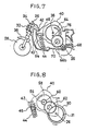
- a front end of the moving portion 40 protrudes forward and has on a bottom surface a recess 43 receiving an upper end of a coil spring 44 which is disposed so as to expand and contract in upper and lower directions in the body 22 as shown in Fig. 7.
- the moving portion 40 is urged to an inner wall surface of the body 22 by the spring 44 at the front end 42, and the upper part of the moving portion 40 appears from the body 22.
- a supplementary weight 45 (Fig. 8) for moving the center of gravity of the moving portion 40 toward the front end 42.
- a protrusion 46 is provided at the position where it cannot be in contact with the spring 44 and the supplementary weight 45, and a member 50 forms part of the moving portion 40 by being pivotally mounted thereon by an axial pin 48 attached to the protrusion 46 as shown in Fig. 9. While one end of the member 50 is supported by the axial pin 48, other end extends to the center of the moving portion 40.
- the member 50 is pulled by a spring 52 disposed between a middle portion of the member 50 and an inner wall surface of the moving portion 40, and is kept against the inner wall of the body 22.
- a stopper member in the form of a .detention protrusion 54 which holds the moving portion 40 at the position where it is pushed (Fig. 10) by engagement with an end of the member 50 when the moving portion 40 is pushed down while the spring 44 is pressed.
- a rotary member which liberates the engagement between the member 50 and the detention protrusion 54 (which operates as a kind of timer) when the rear wheel 30 has rotated a certain degree of rotation.
- the driving means of the rear wheel 30 comprises a flywheel 58 which rotates with an axle 56 attached to the moving portion 40 in the center, a pinion 60 which is coaxial and rotates with the flywheel as one body, and a stepped gear 62 consisting of a greater-diameter portion meshing with the pinion 60 and a smaller-diameter portion meshing with a coaxial gear 31 provided as one body in the left side of the rear wheel 30. Accordingly, it is possible to energize, that is, to give the rotational force to the flywheel 58 by rotating the rear wheel 30.
- the flywheel 58 is used as a power source to rotate the rear wheel 30, it is used as means providing a necessary mass for beating the moving portion 40 against the body 22 to loop the running toy.
- the flywheel has the role as a power source driving the stopper-release means mentioned below.
- a deformed gear 64 which rotates with the axle 56 of the moving portion 40 in the center and independently of the flywheel 58 as shown in Figs. 6 and 7, as a rotary member for releasing the engagement between the member 50 and the detention protrusion 54 when the rear wheel 30 has rotated a certain degree.
- a stepped transmission gear 66 having a smaller-diameter portion 66a meshing with the deformed gear 64, and a pinion 68 which is attached to the axle 26 of the rear wheel 30 as one body and is meshing with a greater-diameter portion 66b of the transmission gear 66, to con- structthe stopper-release means together with the deformed gear 64.
- an axle 70 of the transmission gear 66 penetrates through the right side casing of the moving portion 40 and the body 22 and protrudes outside.
- a push button 72 is attached to the tip of the axle 70, and a coil spring 74 surrounding the axle 70 is disposed between the push button 72 and the body 22. The circumference of the coil spring 74 and the push button 72 is hidden by a cylindrical protrusion 22a formed in the body 22.
- the transmission gear 66 meshes with the deformed gear 64 and the pinion 68 of the rear wheel 30 to transmit the rotation of the rear wheel 30 to the deformed gear 64.
- the transmission gear 66 is disengaged from the defined gear 64 and the pinion 68, so that it cannot be rotated in spite of the rotation of the rear wheel 30. Stopping pushing the button 72, the push button 72 and the transmission gear 66 are urged back where they were by the force of the spring 74.
- the deformed gear 64 is formed as follows by a plastic material usually used for toys. As shown in Fig. 9, the deformed gear 64 has a part 64a of its circumference formed by a curve, curvature radius of which being more than that of other part, a gear portion which has flexibility given by cutting from a point of the curve part 64a in a shape of arc, and a tooth-lacked part 64b formed at a position slightly distanced from a starting point of the cutout 65 in an opposite direction.
- a projection 76 which engages with an end of the member 50 extending to the center of the moving portion 40 so as to slightly rotate the member 50 in a clockwise direction in the drawing.
- the position of the projection 76 is set so that the projection 76 can push the end of the member 50 to release the engagement with the detention protrusion 54 when the gear portion adjoining the starting point of the cutout 65 of the deformed gear 64 meshes with the smaller-diameter portion 66a of the transmission gear 66 as shown in Figs. 12 and 13, in the state where the other end of the member 50 is engaging with the detention protrusion 54 in the body 22.
- the curvature radius of the part 64a of the deformed gear 64 is made greater, which part engages with the smaller-diameter portion 66a of the transmission gear 66 when the protrusion 76 releases the engagement as mentioned above, whereby the engagement between the deformed gear 64 and the smaller-diameter portion 66a of the transmission gear 66 is maintained even if the deformed gear 64 has moved upward.
- the deformed gear 64 must be in mesh with the smaller diameter portion 66a of the transmission gear 66 at a constant diameter (which is smaller than the curvature radius of the curve part 64a mentioned above).
- the arched cutout 65 is formed in the curve part 64a of the deformed gear 64 which is meshing with the smaller-diameter portion 66a before the protrusion 76 releases the engagement as mentioned above, so that the flexibility is given to the part 64a.
- the gear portion of the deformed gear 64 meshing with the smaller-diameter portion 66a of the transmission gear 66 is retired to the diameter equal to that of other portion before the protrusion 76 releases the engagement.
- the toy motorcycle as shown operates as explained below.
- the moving portion 40 which is in the upper position as shown in Fig. 7 is pushed down until the end of the member 50 engages with the detention protrusion 54.
- the push button 72 in the right side of the body 22 is pressed by a finger, the rear wheel 30 is rotated by pushing it forward on the floor. Accordingly, the rotational force is transmitted from the gear 31 formed as one body in the rear wheel 30 to the flywheel 58 through the stepped gear 62 and the pinion 60.
- the deformed gear 64 is not rotated wherever the tooth-lacked part 64b is positioned because the transmission gear 66 of the stopper-release means is not in mesh with either the pinion 68 of the rear axle 26 or the deformed gear 64.
- the rear wheel 30 is driven by the rotational force of the flywheel 58 and thus the toy begins to run forward.
- the transmission gear 66 meshes with both of the pinion 68 of the rear axle 26 and the deformed gear 64, and thus the rotation of the rear wheel 30 is transmitted to the deformed gear 64, which is rotated in the counterclockwise direction in Fig. 10 and the following figures.
- the deformed gear 64 has already been reset in the position of Fig. 9 after the restriction of the moving portion 40 was ceased, the deformed gear 64 begins to rotate from this position.
- the flywheel 58 was energized without pushing the push button 72, the deformed gear 64 would have been rotated from the reset position before the toy begins to run on the floor.
- the deformed gear 64 With the rotation of the deformed gear 64, the projection 76 on the surface thereof is in engagement with the end of the member 50 as shown in Fig. 11, whereby the member 50 is rotated in the clockwise direction with the axial pin 48 in the center, and the other end of the member 50 gradually slides up underneath the detention protrusion 54 of the body 22.
- the deformed gear 64 meshes with the smaller-diameter portion 66a of the transmission gear 66 at the gear part 64a having flexibility as shown in Fig. 12, and the starting point of the cutout 65 approaches to the smaller-diameter portion 66a.
- the moving portion 40 When the end of the member 50 has got over the tip of the detention protrusion 54, the moving portion 40 is rotated upward in a moment with the rear axle 26 as a fulcrum by the resilient force of the contracted spring 44, and then the front end 42 collides against the inner wall surface of the upper portion of the body 22 (Fig. 13). In this case, the deformed gear 64 keeps the engagement with the smaller-diameter portion 66a of the transmission gear 66 at the starting point of the cutout 65. When the moving portion 40 is pushed up, the deformed gear 64 gets over the starting point of the cutout 65 simultaneously and is in mesh with the smaller-diameter portion 66a until the tooth-lacked part 64b comes thereto.
- the time interval or distance from the start of running to that of jumping is determined by a time when the projection 76 on the deformed gear 64 detaches the end of the member 50 from the tip of the detention protrusion 54. Accordingly, as far as the deformed gear 64 begins to rotate from the reset condition shown in Fig. 9, the running toy jumps up after it runs a constant distance corresponding to the rotational speed of the rear wheel 30. Meanwhile, if the deformed gear 64 has already been rotated from the reset position by energizing the flywheel 58 without pushing the push button 72, the toy jumps up earlier the time corresponding to that.
Landscapes
- Toys (AREA)
Description
- This invention relates to a running toy which performs jumping or somersault operation.
- A running toy which performs a somersault operation has been disclosed by Japanese Patent Publication No. 54-16780. The running toy according to that patent of the present applicant has a swingable lever which at one of its ends is pivotally mounted in a body of the toy, with a weight at its opposite end disposed outside of the body. In use the lever is pushed down against the force of a spring and restrained by a stopper. The toy is then pushed to run by hand and the resilient force which has been stored in the spring is released all at once when the toy has run a predetermined distance and the lever is released, whereby the toy jumps up above the path and somersaults.
- However, because this toy has a heavy weight which projects out of its body, its momentum is usually spent after it has somersaulted so that the toy would not keep running. Of course, it might be possible to extend the running distance if the toy were to be made small and light, but it is inevitable that this would result in the reduction of the size and mass of the swingable lever which constitutes the moving portion for causing jumping. As a result, the jumping force would be reduced and the toy becomes less interesting.
- Therefore, the running toy mentioned above might be suitable for relatively young children, but its operation would not be satisfactory for activity toys such as stunt car and motorcycle which attach importance to the ability of running after jumping.
- Accordingly, an object of the invention is to provide an improved running toy.
- According to this invention, there is provided a running toy comprising a housing having wheels for running and a downward facing inner surface, a moving portion disposed in said housing so as to move in the up and down directions and transfer its movement energy to the housing by impact with the inner surface, a spring which imparts an upward force to said moving portion, a stopper member which holds said moving portion at the position where it is pushed down against the resilient force of said spring, a timing gear driven by one of said wheels, and release means attached to said timing gear for releasing engagement between the moving portion and said stopper member when said timing gear is rotated by a predetermined amount, characterised by said moving portion comprising a weight which has a recess formed in a bottom surface thereof, and said spring is disposed in said recess so as to expand and contract in the up and down directions.
- Preferably the running toy includes a timing gear return mechanism for automatically returning said timing gear to a starting position.
- In one embodiment, the running toy comprises an axle for said wheels and a worm gear fitted to the axle and engaging said timing gear, said release means comprising a cam provided in concentric relationship with the timing gear or a projection provided on a surface of the timing gear in an eccentric manner.
- Desirably the axles of the wheels for running penetrate through elongated holes that are formed on both sides of the housing, the holes being elongated in the up and down directions, and when the housing is lifted up, the axles of wheels for running descend along the holes due to their own weight, whereby the worm gear fitted to the axle of the wheels, for running disengages from the timing gear.
- According to another preferred embodiment of the invention, the moving portion includes a flywheel that rotatably drives the wheels for running, and the release means comprises a projection that releases the engagement between the moving portion and said stopper member when the timing gear is rotated to a predetermined position.
- The moving portion preferably includes a transmission gear which is positioned between a coaxial gear rotating with the wheels for running and the timing gear, and the timing gear comprises a deformable gear having a nondeformable part formed by a nondeformable curve with a curvature radius which is more than that of another, deformable part measured from the same center, the deformable part given flexibility by an arcuate slot opposite the nondeformable part, and having a cutout part formed at a position slightly distanced from a starting point of the arcuate slot, the cutout part facing the transmission gear when the moving portion abuts on the inner surface of the housing, said deformable gear meshing with the transmission gear when the moving portion is at the position where it is pushed down, and teeth at the starting point of the cutout part of the deformable gear meshing with the transmission gear when the projection comes to the position where it releases the restraint of said moving portion by the stopper member during rotation of the deformable gear.
- The transmission gear is preferably arranged to disengage from the coaxial gear and the timing gear by pushing a button projected outside of the body.
- The invention will now be described, by way of example, with reference to the accompanying drawings, in which:
- Fig. 1 is a perspective view of a toy car according to an embodiment of the invention;
- Fig. 2 is a perspective view illustrating the internal construction of the toy car;
- Fig. 3 is a partial sectional view of the toy car;
- Fig. 4 is a perspective view illustrating the internal construction of another toy car;
- Fig. 5 is a side view of a motorcycle according to another embodiment of the invention;
- Fig. 6 is a sectional view along the line VI-VI of Fig. 5;
- Fig. 7 is a partial sectional view;
- Fig. 8 is a sectional view of the moving portion along the line VIII-VIII of Fig. 6;
- Fig. 9 is a sectional view illustrating a stopper- releasing mechanism of the movable portion; and
- Figs. 10 to 14 are partial sectional views showing the change of state from the start of running to the jumping operation.
- Fig. 1 shows a toy car according to a preferred embodiment of the invention, and Figs. 2 and 3 show the internal construction thereof. The toy car has a housing 1 of the shape of the body of a passenger car, and front and rear pairs of
wheels front axle 2a and arear axle 2b that penetrate through both side walls of the housing. To thefront axle 2a is attached a worm gear 4 which meshes with a spur gearthatwill be mentioned later. Throughholes 5 where theaxles holes 5 to support the housing 1 as shown in Fig. 3. When the toy car is lifted up, on the other hand, the axles descend to the lower ends of the throughholes 5 due to their own weight and a weight of thewheels - A moving portion or
member 6 consisting of a weight having the shape of rectangular paral- lelopiped is disposed at a central position in the housing 1 so as to move in the upper and lower directions. On the upper surface of the movingmember 6, there are provided aprotuberance 7 of a smaller diameter in concentric therewith and ashaft 8 which upwardly stretches from the center of theprotuberance 7 and penetrates through the upper wall of the housing 1 (roof of the car). A push button 9 is attached to the upper end of theshaft 8. Arecess 6a of a circular shape in cross section is formed in the lower surface of the movingmember 6 as shown in Fig. 3, and acoil spring 10 is accommodated to freely expand and contract therein. - Above the moving
member 6, there is disposed a nearly L-shaped stopper member 11 in the back and forth direction to hold the movingmember 6 at a lower position against the resilient force of thespring 10 as shown in Fig. 2. Thestopper member 11 is supported at itsrear end 11 b by apin 12 so as to rotate in the horizontal direction, and has a forwardly stretching portion of an inverted L-shape in cross section so as to come into engagement with the upper edge portion of theprotuberance 7 on the upper surface of the moving member. Further, the front end of thestopper member 11 is downwardly bent, and itslower end 11 a is forwardly protruded. - The
stopper member 11 of the above-mentioned shape is pulled to turn in the counterclockwise direction as viewed from the upper side with thepin 12 as a center, by aspring 13 which is disposed between the bent portion of thestopper member 11 and a portion of the housing 1. When the movingmember 6 is lifted up to the upper position by thespring 10 as shown in Fig. 3, thestopper member 11 comes into contact with the side surface ofprotuberance 7 on the movingmember 6. Here, if the push button 9 is depressed by a finger against the force of thespring 10 to lower the movingmember 6 and theprotuberance 7, thestopper member 11 slightly turns in the counterclockwise direction, engages with the upper edge of theprotuberance 7, and holds the movingmember 6 at the lower position. - A
spur gear 14 is disposed to mesh with the worm gear 4 between thelower end 11 a of thestopper member 11 and thefront axle 2a. Aneccentric pin 15 is studded on the upper surface of thespur gear 14. When thepin 15 comes into engagement with thelower end 11 a of thestopper member 11 to push it in the clockwise direction, the movingmember 6 is held no more at the lower position by thestopper member 11. To bring thepin 15 to a predetermined start position, furthermore, aspring 16 is connected between thepin 15 and a portion of the housing 1. - Being constructed as mentioned above, the toy car of Fig. 1 operates as described below.
- The toy is placed on the floor or any other plane, and the push button 9 protruding beyond the roof of the car is depressed. The moving
member 6 therefore is lowered and is held at the lower position by thestopper member 11 as mentioned above. Fig. 2 illustrates this condition. In this case, the worm gear 4 of thefront axle 2a is in mesh with thespur gear 14, and thepin 15 is located at the starting position as shown. This is because, if the toy is once lifted up prior to placing it on a plane, theaxle 2a descends to the lower end of throughholes 5 of the housing 1, and the worm gear 4 disengages from thespur gear 14. Therefore, thespur gear 14 and thepin 15 are returned to the starting position being pulled by thespring 16. - Under this condition, if the toy is forcibly pushed forward to run, the rotation of the worm gear 4 causes the
spur gear 14 and thepin 15 rotate in the direction of arrow of Fig. 2 overcoming the pulling force of thespring 16. Then, thepin 15 comes into engagement with thelower end 11a of thestopper member 11 to push it. Therefore, the movingmember 6 is no more held by thestopper member 11, and is abruptly pushed up by the resilient force of thespring 10. Accordingly, theprotuberance 7 of the movingmember 6 comes into collision with the inner side of-the ceiling, and thus the toy jumps up due to that force. Here, since the movingmember 6 is located at the center of the car body, the toy car jumps up. - As described above, the toy car performs the jumping operation when it has run a predetermined distance, i.e., when the
pin 15 is turned to a position at which the movingmember 6 is no more held by thestopper member 11. According to the invention, furthermore, the toy car can be constructed to perform somersault operation by changing the position of the moving member. - Fig. 4 shows a toy car which performs somersault operation after it has run a predetermined distance according to modified embodiment of the invention. The construction of this embodiment is fundamentally the same as the toy of Fig. 1, but is different with respect to the points mentioned below.
- First, the direction in which the toy proceeds is opposite. That is, the worm gear 4 is attached to the
axle 2b of therear wheels 3b. When theaxle 2b rotates forward as indicated by arrow, thespur gear 14 rotates in the counterclockwise direction. - A
cam 17 is provided on the upper surface of thespur gear 14 in concentric therewith, and the protruded portion of thecam 17 comes into engagement with thelower end 11 a of thestopper member 11 to push it leftwards, so that the movingmember 6 is no more held at the lower position by thestopper member 11. - Further, the
spring 13 is hooked to the downwardly bent portion of thestopper member 11 to turn it in the counterclockwise direction. - Moreover, the moving
member 6 has a columnar shape and is disposed in a front portion of the car body. - Therefore, if the toy is vigorously pushed forward like the above-mentioned case, the rotation of the worm gear 4 causes the
spur gear 14 to rotate in the direction of arrow in Fig. 4.overcoming the pulling force ofspring 16. Thecam 17 then comes into engagement with thelower end 11 a of thestopper member 11 to push it, whereby the movingmember 6 is liberated from thestopper member 11 and is suddenly pushed up by the resilient force of thespring 10. Consequently, theprotuberance 7 of the movingmember 6 comes into collision with the inner side of the roof, and the toy jumps up due to that force. In this case, the movingmember 6 is located in the front portion of the car body, and the upward force of the movingmember 6 is imparted to the front portion of the roof. Accordingly, the car somersaults rearwardly and lands on the ground. - Although the foregoing description has dealt with two types of toy car, the invention is in no way limited thereto. For example, the mechanism for liberating the moving member from the stopper member may be any one which operates being interlocked to the rotation of wheels, and need not be limited to the one which is shown in the drawings.
- Next, Fig. 5 shows a toy motorcycle according to another preferred embodiment of the invention, and Fig. 6 is a sectional view along the line VI-VI, which shows the internal construction of the toy. The toy motorcycle comprises a
hollow body 22 of the shape of a motorcycle, and front andrear wheels axles like rubber tire 30a is wound around arearwheel 30. - Afront end of the
body 22 has a through hole 34 (Fig. 7), through which an upper portion of a tiltedhandle shaft 32 penetrates loosely to move in upper and lower directions, and has an upper surface plate which is formed as one body to hide anupper end 33 of thehandle shaft 32. Theupper end 33 of thehandle shaft 32 is shaped greater in diameter and flat so that it cannot fall out of the throughhole 34. A middle portion of thehandle shaft 32 is shaped as a step supporting the front portion of thebody 22 through contact with a bottom surface of the front end of thebody 22. A lower portion of thehandle shaft 32 diverges into two extended portions, between which portions thefront wheel 28 is rotatably supported by theaxle 24 as a fulcrum and afender formation 38 is provided. - In the
body 22, a movingportion 40 which is formed by joining left and right cases as shown in Fig. 6, is swingably mounted in upper and lower directions at therear axle 26 as a fulcrum. A front end of the movingportion 40 protrudes forward and has on a bottom surface arecess 43 receiving an upper end of acoil spring 44 which is disposed so as to expand and contract in upper and lower directions in thebody 22 as shown in Fig. 7. Normally, the movingportion 40 is urged to an inner wall surface of thebody 22 by thespring 44 at thefront end 42, and the upper part of the movingportion 40 appears from thebody 22. In therecess 43 there is disposed a supplementary weight 45 (Fig. 8) for moving the center of gravity of the movingportion 40 toward thefront end 42. - Under the
front end 42 of the movingportion 40, aprotrusion 46 is provided at the position where it cannot be in contact with thespring 44 and thesupplementary weight 45, and amember 50 forms part of the movingportion 40 by being pivotally mounted thereon by anaxial pin 48 attached to theprotrusion 46 as shown in Fig. 9. While one end of themember 50 is supported by theaxial pin 48, other end extends to the center of the movingportion 40. Themember 50 is pulled by aspring 52 disposed between a middle portion of themember 50 and an inner wall surface of the movingportion 40, and is kept against the inner wall of thebody 22. - On the inner surface of the front portion of the
body 22, is formed a stopper member in the form of a .detention protrusion 54 which holds the movingportion 40 at the position where it is pushed (Fig. 10) by engagement with an end of themember 50 when the movingportion 40 is pushed down while thespring 44 is pressed. - Inside of the moving
portion 40, there are accommodated means for driving therear wheel 30 and stopper release means including a rotary member which liberates the engagement between themember 50 and the detention protrusion 54 (which operates as a kind of timer) when therear wheel 30 has rotated a certain degree of rotation. - First, as shown in Figs. 6 and 8, the driving means of the
rear wheel 30 comprises aflywheel 58 which rotates with anaxle 56 attached to the movingportion 40 in the center, apinion 60 which is coaxial and rotates with the flywheel as one body, and a steppedgear 62 consisting of a greater-diameter portion meshing with thepinion 60 and a smaller-diameter portion meshing with acoaxial gear 31 provided as one body in the left side of therear wheel 30. Accordingly, it is possible to energize, that is, to give the rotational force to theflywheel 58 by rotating therear wheel 30. - According to the present invention, while the
flywheel 58 is used as a power source to rotate therear wheel 30, it is used as means providing a necessary mass for beating the movingportion 40 against thebody 22 to loop the running toy. In addition, the flywheel has the role as a power source driving the stopper-release means mentioned below. - Next, the stopper-release means assembled in the moving
portion 40 will be explained. First, there is disposed adeformed gear 64 which rotates with theaxle 56 of the movingportion 40 in the center and independently of theflywheel 58 as shown in Figs. 6 and 7, as a rotary member for releasing the engagement between themember 50 and thedetention protrusion 54 when therear wheel 30 has rotated a certain degree. Also, there are disposed a steppedtransmission gear 66 having a smaller-diameter portion 66a meshing with thedeformed gear 64, and apinion 68 which is attached to theaxle 26 of therear wheel 30 as one body and is meshing with a greater-diameter portion 66b of thetransmission gear 66, to con- structthe stopper-release means together with thedeformed gear 64. Here, anaxle 70 of thetransmission gear 66 penetrates through the right side casing of the movingportion 40 and thebody 22 and protrudes outside. Apush button 72 is attached to the tip of theaxle 70, and acoil spring 74 surrounding theaxle 70 is disposed between thepush button 72 and thebody 22. The circumference of thecoil spring 74 and thepush button 72 is hidden by acylindrical protrusion 22a formed in thebody 22. - In the usual state where the
push button 72 is protruded as shown in Fig. 6, thetransmission gear 66 meshes with thedeformed gear 64 and thepinion 68 of therear wheel 30 to transmit the rotation of therear wheel 30 to thedeformed gear 64. When thepush button 72 is pushed against thespring 74 as shown by an arrow, however, thetransmission gear 66 is disengaged from the definedgear 64 and thepinion 68, so that it cannot be rotated in spite of the rotation of therear wheel 30. Stopping pushing thebutton 72, thepush button 72 and thetransmission gear 66 are urged back where they were by the force of thespring 74. - The
deformed gear 64 is formed as follows by a plastic material usually used for toys. As shown in Fig. 9, thedeformed gear 64 has apart 64a of its circumference formed by a curve, curvature radius of which being more than that of other part, a gear portion which has flexibility given by cutting from a point of thecurve part 64a in a shape of arc, and a tooth-lackedpart 64b formed at a position slightly distanced from a starting point of thecutout 65 in an opposite direction. - In the state where the restriction of the moving
portion 40 has been released and thus thedeformed gear 64 has been reset in an initial position as explained later, the tooth-lackedpart 64b of the deformed gear faces the smaller-diameter portion 66a of thetransmission gear 66 as shown in Fig. 9. Therefore, even if thetransmission gear 66 rotates, the rotational force thereof is not transmitted to thedeformed gate 64. When the movingportion 40 is brought to the position where it has been pushed down as shown in Fig. 10, however, thedeformed gear 64 is in a state to be given the rotational force through engagement between the teeth adjoining the tooth-lackedpart 64b and thetransmission gear 66. - On the surface of the deformed gear 64formed is a
projection 76 which engages with an end of themember 50 extending to the center of the movingportion 40 so as to slightly rotate themember 50 in a clockwise direction in the drawing. The position of theprojection 76 is set so that theprojection 76 can push the end of themember 50 to release the engagement with thedetention protrusion 54 when the gear portion adjoining the starting point of thecutout 65 of thedeformed gear 64 meshes with the smaller-diameter portion 66a of thetransmission gear 66 as shown in Figs. 12 and 13, in the state where the other end of themember 50 is engaging with thedetention protrusion 54 in thebody 22. - When the engagement between the other end of the
member 50 and thedetention protrusion 54 is released by the projection 76 (Fig. 13), themovable portion 40 is abruptly pushed up by the resilient force of thespring 44 to rotate as a whole with therear axle 26 in the center. Thus, thedeformed gear 64 is also moved upward. At this time, the rotation of thedeformed gear 64 must be maintained until the tooth-lackedpart 64b reaches the position of the smaller-diameter portion 66a of thetransmission gear 66. For that purpose, the curvature radius of thepart 64a of thedeformed gear 64 is made greater, which part engages with the smaller-diameter portion 66a of thetransmission gear 66 when theprotrusion 76 releases the engagement as mentioned above, whereby the engagement between thedeformed gear 64 and the smaller-diameter portion 66a of thetransmission gear 66 is maintained even if thedeformed gear 64 has moved upward. - Meanwhile, before the
protrusion 76 releases the engagement (Fig. 12), thedeformed gear 64 must be in mesh with thesmaller diameter portion 66a of thetransmission gear 66 at a constant diameter (which is smaller than the curvature radius of thecurve part 64a mentioned above). For that purpose, thearched cutout 65 is formed in thecurve part 64a of thedeformed gear 64 which is meshing with the smaller-diameter portion 66a before theprotrusion 76 releases the engagement as mentioned above, so that the flexibility is given to thepart 64a. Thus the gear portion of thedeformed gear 64 meshing with the smaller-diameter portion 66a of thetransmission gear 66 is retired to the diameter equal to that of other portion before theprotrusion 76 releases the engagement. - Being constructed as mentioned above, the toy motorcycle as shown operates as explained below.
- First of all, the moving
portion 40 which is in the upper position as shown in Fig. 7 is pushed down until the end of themember 50 engages with thedetention protrusion 54. Next, while thepush button 72 in the right side of thebody 22 is pressed by a finger, therear wheel 30 is rotated by pushing it forward on the floor. Accordingly, the rotational force is transmitted from thegear 31 formed as one body in therear wheel 30 to theflywheel 58 through the steppedgear 62 and thepinion 60. At this time, thedeformed gear 64 is not rotated wherever the tooth-lackedpart 64b is positioned because thetransmission gear 66 of the stopper-release means is not in mesh with either thepinion 68 of therear axle 26 or thedeformed gear 64. - If the
body 22 is placed on the floor in such a manner that it is pushed forward, therear wheel 30 is driven by the rotational force of theflywheel 58 and thus the toy begins to run forward. At the same time, thetransmission gear 66 meshes with both of thepinion 68 of therear axle 26 and thedeformed gear 64, and thus the rotation of therear wheel 30 is transmitted to thedeformed gear 64, which is rotated in the counterclockwise direction in Fig. 10 and the following figures. At this time, because thedeformed gear 64 has already been reset in the position of Fig. 9 after the restriction of the movingportion 40 was ceased, thedeformed gear 64 begins to rotate from this position. However, if theflywheel 58 was energized without pushing thepush button 72, thedeformed gear 64 would have been rotated from the reset position before the toy begins to run on the floor. - With the rotation of the
deformed gear 64, theprojection 76 on the surface thereof is in engagement with the end of themember 50 as shown in Fig. 11, whereby themember 50 is rotated in the clockwise direction with theaxial pin 48 in the center, and the other end of themember 50 gradually slides up underneath thedetention protrusion 54 of thebody 22. At this time, thedeformed gear 64 meshes with the smaller-diameter portion 66a of thetransmission gear 66 at thegear part 64a having flexibility as shown in Fig. 12, and the starting point of thecutout 65 approaches to the smaller-diameter portion 66a. - When the end of the
member 50 has got over the tip of thedetention protrusion 54, the movingportion 40 is rotated upward in a moment with therear axle 26 as a fulcrum by the resilient force of the contractedspring 44, and then thefront end 42 collides against the inner wall surface of the upper portion of the body 22 (Fig. 13). In this case, thedeformed gear 64 keeps the engagement with the smaller-diameter portion 66a of thetransmission gear 66 at the starting point of thecutout 65. When the movingportion 40 is pushed up, thedeformed gear 64 gets over the starting point of thecutout 65 simultaneously and is in mesh with the smaller-diameter portion 66a until the tooth-lackedpart 64b comes thereto. - By the collision of the moving
portion 40 the running toy jumps up from the floor. In this case, the toy which jumped up turns a loop rearward as shown in Fig. 14 and lands on the floor because the impact from the movingportion 40 operates at the front of thebody 22. During the time of loop the tooth-lackedpart 64b of thedeformed gear 64 comes to the position of the smaller-diameter portion 66a of thetransmission gear 66 and the rotation of thedeformed gear 64 is stopped, so that thedeformed gear 64 is reset in the timer start position (Fig. 9). The running toy runs forward with therear wheel 30 driven by the rotational force of theflywheel 58 which is maintained even after landing. - The time interval or distance from the start of running to that of jumping is determined by a time when the
projection 76 on thedeformed gear 64 detaches the end of themember 50 from the tip of thedetention protrusion 54. Accordingly, as far as thedeformed gear 64 begins to rotate from the reset condition shown in Fig. 9, the running toy jumps up after it runs a constant distance corresponding to the rotational speed of therear wheel 30. Meanwhile, if thedeformed gear 64 has already been rotated from the reset position by energizing theflywheel 58 without pushing thepush button 72, the toy jumps up earlier the time corresponding to that. - As for the modification of the above-mentioned motorcycle toy, it is possible to change the direction in which the toy jumps by changing the position where the moving portion collides against the body.
Claims (8)
Applications Claiming Priority (4)
| Application Number | Priority Date | Filing Date | Title |
|---|---|---|---|
| JP119870/83U | 1983-08-02 | ||
| JP1983119870U JPS6027998U (en) | 1983-08-02 | 1983-08-02 | traveling toy |
| JP8676584U JPS614699U (en) | 1984-06-13 | 1984-06-13 | traveling toy |
| JP86765/84U | 1984-06-13 |
Publications (3)
| Publication Number | Publication Date |
|---|---|
| EP0133054A2 EP0133054A2 (en) | 1985-02-13 |
| EP0133054A3 EP0133054A3 (en) | 1985-04-03 |
| EP0133054B1 true EP0133054B1 (en) | 1989-01-11 |
Family
ID=26427846
Family Applications (1)
| Application Number | Title | Priority Date | Filing Date |
|---|---|---|---|
| EP19840305220 Expired EP0133054B1 (en) | 1983-08-02 | 1984-08-01 | Running toy |
Country Status (1)
| Country | Link |
|---|---|
| EP (1) | EP0133054B1 (en) |
Families Citing this family (1)
| Publication number | Priority date | Publication date | Assignee | Title |
|---|---|---|---|---|
| JPH0615665Y2 (en) * | 1987-11-19 | 1994-04-27 | 株式会社フレックス | Aerial rotating toys |
Family Cites Families (5)
| Publication number | Priority date | Publication date | Assignee | Title |
|---|---|---|---|---|
| US3398480A (en) * | 1964-09-10 | 1968-08-27 | Shigeichi Hoshikuma | Automatic apparatus for controlling electrically driven toys |
| US3744182A (en) * | 1969-12-08 | 1973-07-10 | Marvin Glass & Associates | Self-propelled toy |
| JPS51148533A (en) * | 1975-06-13 | 1976-12-20 | Tomy Kogyo Co Inc | Running toy |
| JPS524345A (en) * | 1975-06-25 | 1977-01-13 | Tomy Kogyo Co Inc | Running toy |
| GB2066092B (en) * | 1979-12-28 | 1983-06-08 | Shinsei Industries Co | Fly-wheel driven toy motorcycle |
-
1984
- 1984-08-01 EP EP19840305220 patent/EP0133054B1/en not_active Expired
Also Published As
| Publication number | Publication date |
|---|---|
| EP0133054A3 (en) | 1985-04-03 |
| EP0133054A2 (en) | 1985-02-13 |
Similar Documents
| Publication | Publication Date | Title |
|---|---|---|
| US3886682A (en) | Toy vehicle and launcher | |
| US4959035A (en) | Miniature storage container for a manually propelled toy member | |
| US4087935A (en) | Toy vehicle with housing | |
| US6224457B1 (en) | Knockdown style safety disk-shooting toy | |
| US3772824A (en) | Toy vehicle apparatus | |
| JPS6330479Y2 (en) | ||
| US4418495A (en) | Miniature racing vehicle and wrist-borne launching platform assembly | |
| US5460560A (en) | Sparking toy vehicle and launcher therefor | |
| US20020072294A1 (en) | Race car and track | |
| US4526554A (en) | Toy motorcycle and launcher apparatus | |
| US4443967A (en) | Flywheel driven toy car | |
| US4479326A (en) | Sparking toy vehicle and launcher | |
| US4556396A (en) | Stunt-performing toy vehicle | |
| US4490124A (en) | Running toy | |
| US4309841A (en) | Two-wheel toy vehicle with inertia flywheel | |
| US4693697A (en) | Push-pull toy | |
| US3238665A (en) | Movable element wheeled action toy | |
| US3702037A (en) | Toy vehicle system featuring pivotable toy vehicle | |
| US4143484A (en) | Drive mechanism for a running toy | |
| EP0700703A2 (en) | Vehicle toy mounting projectile launching mechanism | |
| EP0133054A2 (en) | Running toy | |
| US3769746A (en) | Rubber band drive for toy vehicle | |
| JP2004275484A (en) | Remote-controlled top toy | |
| US3494617A (en) | Game board with self-propelled vehicle | |
| GB2132493A (en) | Toy vehicle assembly |
Legal Events
| Date | Code | Title | Description |
|---|---|---|---|
| PUAI | Public reference made under article 153(3) epc to a published international application that has entered the european phase |
Free format text: ORIGINAL CODE: 0009012 |
|
| PUAL | Search report despatched |
Free format text: ORIGINAL CODE: 0009013 |
|
| AK | Designated contracting states |
Designated state(s): FR GB IT |
|
| AK | Designated contracting states |
Designated state(s): FR GB IT |
|
| 17P | Request for examination filed |
Effective date: 19850422 |
|
| 17Q | First examination report despatched |
Effective date: 19860618 |
|
| D17Q | First examination report despatched (deleted) | ||
| GRAA | (expected) grant |
Free format text: ORIGINAL CODE: 0009210 |
|
| AK | Designated contracting states |
Kind code of ref document: B1 Designated state(s): FR GB IT |
|
| PG25 | Lapsed in a contracting state [announced via postgrant information from national office to epo] |
Ref country code: IT Free format text: LAPSE BECAUSE OF FAILURE TO SUBMIT A TRANSLATION OF THE DESCRIPTION OR TO PAY THE FEE WITHIN THE PRESCRIBED TIME-LIMIT;WARNING: LAPSES OF ITALIAN PATENTS WITH EFFECTIVE DATE BEFORE 2007 MAY HAVE OCCURRED AT ANY TIME BEFORE 2007. THE CORRECT EFFECTIVE DATE MAY BE DIFFERENT FROM THE ONE RECORDED. Effective date: 19890111 Ref country code: FR Free format text: THE PATENT HAS BEEN ANNULLED BY A DECISION OF A NATIONAL AUTHORITY Effective date: 19890111 |
|
| EN | Fr: translation not filed | ||
| PLBE | No opposition filed within time limit |
Free format text: ORIGINAL CODE: 0009261 |
|
| STAA | Information on the status of an ep patent application or granted ep patent |
Free format text: STATUS: NO OPPOSITION FILED WITHIN TIME LIMIT |
|
| 26N | No opposition filed | ||
| PGFP | Annual fee paid to national office [announced via postgrant information from national office to epo] |
Ref country code: GB Payment date: 19900727 Year of fee payment: 7 |
|
| PG25 | Lapsed in a contracting state [announced via postgrant information from national office to epo] |
Ref country code: GB Effective date: 19910801 |
|
| GBPC | Gb: european patent ceased through non-payment of renewal fee |