EP0131720A1 - Gear selection and engagement device for a motor vehicle transmission - Google Patents
Gear selection and engagement device for a motor vehicle transmission Download PDFInfo
- Publication number
- EP0131720A1 EP0131720A1 EP84106041A EP84106041A EP0131720A1 EP 0131720 A1 EP0131720 A1 EP 0131720A1 EP 84106041 A EP84106041 A EP 84106041A EP 84106041 A EP84106041 A EP 84106041A EP 0131720 A1 EP0131720 A1 EP 0131720A1
- Authority
- EP
- European Patent Office
- Prior art keywords
- shaft
- teeth
- axially
- hubs
- preset
- Prior art date
- Legal status (The legal status is an assumption and is not a legal conclusion. Google has not performed a legal analysis and makes no representation as to the accuracy of the status listed.)
- Granted
Links
- 230000005540 biological transmission Effects 0.000 title claims abstract description 19
- 230000000875 corresponding effect Effects 0.000 claims description 28
- 238000006073 displacement reaction Methods 0.000 claims description 19
- 230000008878 coupling Effects 0.000 claims description 2
- 238000010168 coupling process Methods 0.000 claims description 2
- 238000005859 coupling reaction Methods 0.000 claims description 2
- 238000010276 construction Methods 0.000 description 1
Images


Classifications
-
- F—MECHANICAL ENGINEERING; LIGHTING; HEATING; WEAPONS; BLASTING
- F16—ENGINEERING ELEMENTS AND UNITS; GENERAL MEASURES FOR PRODUCING AND MAINTAINING EFFECTIVE FUNCTIONING OF MACHINES OR INSTALLATIONS; THERMAL INSULATION IN GENERAL
- F16H—GEARING
- F16H63/00—Control outputs from the control unit to change-speed- or reversing-gearings for conveying rotary motion or to other devices than the final output mechanism
- F16H63/02—Final output mechanisms therefor; Actuating means for the final output mechanisms
- F16H63/08—Multiple final output mechanisms being moved by a single common final actuating mechanism
- F16H63/20—Multiple final output mechanisms being moved by a single common final actuating mechanism with preselection and subsequent movement of each final output mechanism by movement of the final actuating mechanism in two different ways, e.g. guided by a shift gate
- F16H63/206—Multiple final output mechanisms being moved by a single common final actuating mechanism with preselection and subsequent movement of each final output mechanism by movement of the final actuating mechanism in two different ways, e.g. guided by a shift gate the final output mechanisms being mounted coaxially on a single shaft, e.g. mono rail shift mechanism
-
- F—MECHANICAL ENGINEERING; LIGHTING; HEATING; WEAPONS; BLASTING
- F16—ENGINEERING ELEMENTS AND UNITS; GENERAL MEASURES FOR PRODUCING AND MAINTAINING EFFECTIVE FUNCTIONING OF MACHINES OR INSTALLATIONS; THERMAL INSULATION IN GENERAL
- F16H—GEARING
- F16H63/00—Control outputs from the control unit to change-speed- or reversing-gearings for conveying rotary motion or to other devices than the final output mechanism
- F16H63/02—Final output mechanisms therefor; Actuating means for the final output mechanisms
- F16H63/30—Constructional features of the final output mechanisms
- F16H63/32—Gear shift yokes, e.g. shift forks
- F16H2063/321—Gear shift yokes, e.g. shift forks characterised by the interface between fork body and shift rod, e.g. fixing means, bushes, cams or pins
-
- F—MECHANICAL ENGINEERING; LIGHTING; HEATING; WEAPONS; BLASTING
- F16—ENGINEERING ELEMENTS AND UNITS; GENERAL MEASURES FOR PRODUCING AND MAINTAINING EFFECTIVE FUNCTIONING OF MACHINES OR INSTALLATIONS; THERMAL INSULATION IN GENERAL
- F16H—GEARING
- F16H61/00—Control functions within control units of change-speed- or reversing-gearings for conveying rotary motion ; Control of exclusively fluid gearing, friction gearing, gearings with endless flexible members or other particular types of gearing
- F16H61/26—Generation or transmission of movements for final actuating mechanisms
-
- Y—GENERAL TAGGING OF NEW TECHNOLOGICAL DEVELOPMENTS; GENERAL TAGGING OF CROSS-SECTIONAL TECHNOLOGIES SPANNING OVER SEVERAL SECTIONS OF THE IPC; TECHNICAL SUBJECTS COVERED BY FORMER USPC CROSS-REFERENCE ART COLLECTIONS [XRACs] AND DIGESTS
- Y10—TECHNICAL SUBJECTS COVERED BY FORMER USPC
- Y10T—TECHNICAL SUBJECTS COVERED BY FORMER US CLASSIFICATION
- Y10T74/00—Machine element or mechanism
- Y10T74/20—Control lever and linkage systems
- Y10T74/20012—Multiple controlled elements
- Y10T74/20018—Transmission control
- Y10T74/20085—Restriction of shift, gear selection, or gear engagement
- Y10T74/20104—Shift element interlock
Definitions
- the present invention relates to a gear selection and engagement device designed for assembly on a motor vehicle transmission of the type comprising a number of gears moved axially by corresponding control forks, each of the said gears being designed to be moved into such a position as to mesh with another axially-fixed gear, so as to form a gear pair with a preset transmission ratio.
- one aim of the present invention is to provide a gear selection and engagement device for use on the abovemention ed type of transmission, the said device comprising a sin gle moving control shaft designed to shift the said forks which are needed for both gear selection and engagement.
- Another aim of the present invention is to provide a device of the abovementioned type designed to control a large number of forks and, therefore, employable on trans missions with a particularly large number of gears, e.g. the transmission on an industrial vehicle.
- a further aim of the present invention is to provide a highly compact device ensuring smooth, reliable operation.
- the present invention relates to a gear selection and engagement device for a motor vehicle transmission comprising a number of axially-moving gears, each designed to be moved into such a position as to mesh with another axially-fixed gear so as to form a gear pair with a preset transmission ratio, the said axially-moving gears being controlled by corresponding axially-moving control forks, characterised by the fact that the said device comprises a shaft moving in the direction of and round its own axis in relation to the transmission case by means of manually-operated control means, the said shaft constituting a support for a number of hubs each integral with a corresponding fork; a first set of teeth projecting radially from the said shaft and being axially and torsionally integral with the same and one of the said hubs being arranged between two adjacent teeth on the said first set; a second set of teeth projecting radially from the said shaft, being tor sionally integral with it and axially fixed in relation to the said case
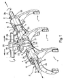
- the device covered by the present invention is designed for use on a motor vehicle transmission (not shown) comprising a number of axially-moving gears, each designed to be moved by a corresponding fork ( 1 ) into such a position as to mesh with another axially-fixed gear, so as to form a gear pair with a preset transmission ratio.
- a motor vehicle transmission (not shown) comprising a number of axially-moving gears, each designed to be moved by a corresponding fork ( 1 ) into such a position as to mesh with another axially-fixed gear, so as to form a gear pair with a preset transmission ratio.
- the device is privided with three such forks designed to shift corresponding gears axially in two opposite directions.
- the device comprises a shaft (2) moving in the direction of and round its own axis in relation to the transmission case.
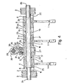
- the end sections (2a, 2b) of the said shaft are housed in correspond ing bearings of walls 3 on the said case.
- Shaft 2 constitutes a support for a number of hubs (4, 5 , 6) each integral with a corresponding fork ( 1 ) as shown clearly in Fig. l .
- the said hubs are thus free to move axially and to turn in relation to the centre part (7) of shaft 2 , the said centre part (7) being greater in diameter than end sections 2 a and 2 b on the shaft.
- the device also comprises a first set of teeth projecting radially from shaft 2 and both axially and torsionally integral with it.
- the said teeth are arranged on the shaft so that one of hubs 4, 5 or 6 fits between two adjacent teeth. Consequently, in the arrangement shown, which provides for only three hubs, the teeth are four in number (8, 9, 10, 11) as shown clearly in the Fig. 4 section.
- key 1 4 housed inside a corresponding annular groove ( 15 ) in the centre part (7) of shaft 2.
- the said teeth project from the same side of the said key the base section of which is housed in the said groove.
- the device also comprises a second set of teeth also pro jecting radially from the centre part (7) of shaft 2 and being torsionally integral with the shaft and fixed axially in relation to the transmission case.
- a second set of teeth also pro jecting radially from the centre part (7) of shaft 2 and being torsionally integral with the shaft and fixed axially in relation to the transmission case.
- one of hubs 4, 5 or 6 is arranged between two adjacent teeth on the said second set.
- the said radial teeth are five in number (16, 17, 18, 19, 20) as shown clearly in the Fig.4 section.
- the teeth in the said second set may also be formed by means of a key (21) also housed in a corresponding longitudinal groove (2 2 ) on the centre part (7) of shaft 2 , the said teeth projecting from one side of the key and the base section of the latter being housed in the said groove.
- Each hub 4, 5 and 6 is provided with at least one pair of axial grooves ( 25 ) each designed to accommodate, in the manner described hereafter, teeth in both the first and second set, when shaft 2 is displaced axially.
- Axial displacement and rotation of shaft 2 are controlled by control means, indicated as a whole by number 2 6, and comprising a first bushing (27), integral with shaft 2, and a second bushing ( 2 8), integral with a control bar ( 2 9) arranged essentially perpendicular to shaft 2.
- the said two bushings are connected by means of an essential ly spherical coupling (30) comprising a head (3 1 ) integral with bushing 28 and connected between a pair of tabs (3 2 ) integral with bushing 27.
- each rotation of control bar 29 round its own axis is accompanied by axial traversing of shaft 2, whereas, traversing of the said bar is accompanied by rotation of the said shaft.
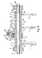
- Grooves 25 on each hub 4 , 5 and 6 are arranged round the circumference of the relative hub in such a preset manner that, for a preset angular position of shaft 2 corresponding to a preset gear selection, all the teeth in the first set are essentially aligned with corresponding grooves on the said hubs, with the exception of the teeth adjacent to a preset hub belonging to the fork which must be displaced axially for engaging the said preset gear.
- each of hubs-5 and 6 is provided on opposite sides of each with a pair of grooves (25) designed to align with teeth 9, 10 and 11, as shown clearly in Fig. 4 , whereas no groove is provided on hub 4 for aligning with teeth 8 and 9.
- Grooves 2 5 on each hub are arranged in such a manner that, with shaft 2 in the abovementioned angular position, the teeth in the second set are aligned with corresponding grooves ( 25 ) on the only hub to be displaced for engaging the preset gear, whereas all the other teeth in the said second set are arranged essentially contacting the other hubs, so as to prevent axial displacement of the said hubs during axial displacement, in the manner hereafter described, of the said preset hub.
- grooves 25 are provided only on hub 4 in alignment with teeth 1 6 and 1 7 in the second set, whereas no groove 25 is provided on the other hubs ( 5 , 6) in alignment with the other teeth (18, 19, 20) in the said second set.
- grooves 25 on the hubs depends on the displacement envisaged for fork 1 and will become clearer from the following examination of the way in which the device operates.
- teeth 18, 19 and 20 in the second set are arranged essentially on each side of hubs 5 and 6, thus locking them axially and preventing any displacement during the following engagement operation.
- the latter is achieved by turning control bar 29 which is accompanied by axial traversing of bushing 27 and, consequently, also of shaft 2. If such rotation is anticlockwise in Fig.4, it is accompanied by rightward displacement (Fig.4) of the shaft (Fig.5) during which tooth 8 shifts hub 4 in the same direction, whereas teeth 9 and 10 simply fit into the corresponding grooves (25) on respective hubs 5 and 6.
- a different gear selection may be achieved by turning shaft 2 into an angular position other than the one already described.
- This new position may correspond to such a preset arrangement of grooves 25 on the three hubs (4, 5, 6) as to determine, following axial displace ment of the shaft, axial displacement of another fork in a preset direction or the simultaneous displacement of two of the said forks.
- each hub (4, 5 , 6) with an appropriate number of grooves (2 5 ), the axial displacement of one or more hubs may be controlled while, at the same time, locking the others axially.
Abstract
Description
- The present invention relates to a gear selection and engagement device designed for assembly on a motor vehicle transmission of the type comprising a number of gears moved axially by corresponding control forks, each of the said gears being designed to be moved into such a position as to mesh with another axially-fixed gear, so as to form a gear pair with a preset transmission ratio. one aim of the present invention is to provide a gear selection and engagement device for use on the abovemention ed type of transmission, the said device comprising a sin gle moving control shaft designed to shift the said forks which are needed for both gear selection and engagement. Another aim of the present invention is to provide a device of the abovementioned type designed to control a large number of forks and, therefore, employable on trans missions with a particularly large number of gears, e.g. the transmission on an industrial vehicle. A further aim of the present invention is to provide a highly compact device ensuring smooth, reliable operation.
- With these aims in view, the present invention relates to a gear selection and engagement device for a motor vehicle transmission comprising a number of axially-moving gears, each designed to be moved into such a position as to mesh with another axially-fixed gear so as to form a gear pair with a preset transmission ratio, the said axially-moving gears being controlled by corresponding axially-moving control forks, characterised by the fact that the said device comprises a shaft moving in the direction of and round its own axis in relation to the transmission case by means of manually-operated control means, the said shaft constituting a support for a number of hubs each integral with a corresponding fork; a first set of teeth projecting radially from the said shaft and being axially and torsionally integral with the same and one of the said hubs being arranged between two adjacent teeth on the said first set; a second set of teeth projecting radially from the said shaft, being tor sionally integral with it and axially fixed in relation to the said case and one of the said hubs being arranged between two adjacent teeth on the said second set; each- of the said hubs having at least one pair of axial grooves designed to accommodate teeth on the said first and second sets when the said shaft is shifted axially by the said control means so as to prevent the relative hubs from moving as a consequence of the said axial displacement; the said grooves being arranged round the circumference of each hub in such a preset manner that, for a preset angular position of the said shaft corresponding to a preset gear selection, all the teeth in the first set are aligned axially with corresponding grooves on the said hubs, with the exception of the teeth adjacent to a preset hub belonging to the fork which must be shifted axially for engaging the said preset gear, so that, following subsequent axial displacement of the said shaft, only the said hub preset for engaging the said gear is shifted axially by one of the said adjacent teeth in the said first set; with the said shaft in the said angular position, the second set teeth adjacent to the said preset hub being aligned with the corresponding grooves on the hub and all the other said second set teeth being arranged essentially contacting the other hubs, so as to prevent the said hubs from moving axially during axial displacement of the said hub selected for engaging the said gear.
- one arrangement of the present invention will now be described, by way of a non-limiting example, with reference to the attached drawings in which :
- - Fig.1 shows a view in perspective of the gear selection and engagement device according to the present invention;
- - Fig.2 shows a side view of the device;
- - Fig.3 shows a cross section of the Fig.2 device along line III-III;
- - Fig.4 shows an axial longitudinal section of the device;
- - Fig.s 5 and 6 show two cross sections of the device, as in Fig.4, but in two different operating positions corres ponding to the engagement of two different gears.
- The device covered by the present invention is designed for use on a motor vehicle transmission (not shown) comprising a number of axially-moving gears, each designed to be moved by a corresponding fork (1) into such a position as to mesh with another axially-fixed gear, so as to form a gear pair with a preset transmission ratio. In the arrangement shown, the device is privided with three such forks designed to shift corresponding gears axially in two opposite directions.
- The device comprises a shaft (2) moving in the direction of and round its own axis in relation to the transmission case. For such a purpose, as shown in Fig.2, the end sections (2a, 2b) of the said shaft are housed in correspond ing bearings of
walls 3 on the said case. Shaft 2 constitutes a support for a number of hubs (4, 5, 6) each integral with a corresponding fork (1) as shown clearly in Fig.l. The said hubs are thus free to move axially and to turn in relation to the centre part (7) of shaft 2, the said centre part (7) being greater in diameter than end sections 2a and 2b on the shaft. - The device also comprises a first set of teeth projecting radially from
shaft 2 and both axially and torsionally integral with it. The said teeth are arranged on the shaft so that one ofhubs key 14 housed inside a corresponding annular groove (15) in the centre part (7) ofshaft 2. The said teeth project from the same side of the said key the base section of which is housed in the said groove. - The device also comprises a second set of teeth also pro jecting radially from the centre part (7) of
shaft 2 and being torsionally integral with the shaft and fixed axially in relation to the transmission case. As on the first set of teeth, one ofhubs - To fix the teeth in the said second set axially in relation to the transmission case,
end teeth case 3, whereas, to enable axial movement of shaft 2 in relation to the key, which is fixed axially, the latter is allowed to slide inside thecorresponding groove 22. - Each
hub shaft 2 are controlled by control means, indicated as a whole bynumber 26, and comprising a first bushing (27), integral withshaft 2, and a second bushing (28), integral with a control bar (29) arranged essentially perpendicular toshaft 2. The said two bushings are connected by means of an essential ly spherical coupling (30) comprising a head (31) integral with bushing 28 and connected between a pair of tabs (32) integral with bushing 27. The side surfaces of the said head are conveniently cylindrical and designed to rest on corresponding flat surfaces oftabs 32. Furthermore, a pin (33) (Fig.1) inserted inside the tabs fits through a slot (34) onhead 31. Obviously, therefore, with such a construction arrangement, each rotation ofcontrol bar 29 round its own axis is accompanied by axial traversing ofshaft 2, whereas, traversing of the said bar is accompanied by rotation of the said shaft. Grooves 25 on each hub 4, 5 and 6 are arranged round the circumference of the relative hub in such a preset manner that, for a preset angular position of shaft 2 corresponding to a preset gear selection, all the teeth in the first set are essentially aligned with corresponding grooves on the said hubs, with the exception of the teeth adjacent to a preset hub belonging to the fork which must be displaced axially for engaging the said preset gear. In the arrangement shown, for the preset angular position of shaft 2 shown in Fig.4, each of hubs-5 and 6 is provided on opposite sides of each with a pair of grooves (25) designed to align withteeth hub 4 for aligning withteeth -
Grooves 25 on each hub are arranged in such a manner that, with shaft 2 in the abovementioned angular position, the teeth in the second set are aligned with corresponding grooves (25) on the only hub to be displaced for engaging the preset gear, whereas all the other teeth in the said second set are arranged essentially contacting the other hubs, so as to prevent axial displacement of the said hubs during axial displacement, in the manner hereafter described, of the said preset hub. Consequent ly, in the arrangement shown in Fig.4 and for the angular position of shaft 2 shown in the said Figure, grooves 25 are provided only on hub 4 in alignment withteeth - Clearly, the arrangement of grooves 25 on the hubs depends on the displacement envisaged for fork 1 and will become clearer from the following examination of the way in which the device operates.
- With reference to Fig.4 showing the device covered by the present invention with none of the gears engaged, assume a gear engagement is required, such engagement being performed by shifting rightwards, in Fig.4, fork 1 on the left of the drawing. Axial traversing of
control bar 29, which turns bushing 27 and, consequently, alsoshaft 2, moves shaft 2 into the angular position shown in Fig.4 in whichteeth hubs - In the abovementioned preset gear selection arrangement,
teeth control bar 29 which is accompanied by axial traversing ofbushing 27 and, consequently, also ofshaft 2. If such rotation is anticlockwise in Fig.4, it is accompanied by rightward displacement (Fig.4) of the shaft (Fig.5) during whichtooth 8 shiftshub 4 in the same direction, whereasteeth respective hubs - If another gear is to be engaged, however, such engagement being achieved by shifting leftwards
fork 1 on the left of Fig.4, the selection arrangement is the same as that already described whereas, for engaging the gear,control bar 29 is turned clockwise in Fig.4 so as to shiftshaft 2 and, consequently, also hub 4 leftwards in Fig.4. - This new engagement set-up is shown in Fig.6. As this clearly shows, during such displacement, teeth 10 and 11 in the first set fit into
corresponding grooves 25 on corresponding hubs 5 and 6 which are locked firmly in the idle position by the teeth in the second set. - A different gear selection may be achieved by turning
shaft 2 into an angular position other than the one already described. This new position may correspond to such a preset arrangement of grooves 25 on the three hubs (4, 5, 6) as to determine, following axial displace ment of the shaft, axial displacement of another fork in a preset direction or the simultaneous displacement of two of the said forks. - Obviously, by providing each hub (4, 5, 6) with an appropriate number of grooves (25), the axial displacement of one or more hubs may be controlled while, at the same time, locking the others axially.
- To those skilled in the art it will be clear that changes can be made to the arrangement described of the present invention, both in terms of form and arrangement of the various parts involved, without, however, departing from the scope of the present invention.
Claims (5)
Priority Applications (1)
| Application Number | Priority Date | Filing Date | Title |
|---|---|---|---|
| AT84106041T ATE29565T1 (en) | 1983-06-17 | 1984-05-28 | DEVICE FOR SELECTING AND ENGAGING GEARS FOR AN AUTOMOTIVE TRANSMISSION. |
Applications Claiming Priority (2)
| Application Number | Priority Date | Filing Date | Title |
|---|---|---|---|
| IT8367675A IT1208768B (en) | 1983-06-17 | 1983-06-17 | DEVICE FOR THE SELECTION AND FOR THE ENGINE GEAR IN A CHANGE OF A VEHICLE |
| IT6767583 | 1983-06-17 |
Publications (2)
| Publication Number | Publication Date |
|---|---|
| EP0131720A1 true EP0131720A1 (en) | 1985-01-23 |
| EP0131720B1 EP0131720B1 (en) | 1987-09-09 |
Family
ID=11304405
Family Applications (1)
| Application Number | Title | Priority Date | Filing Date |
|---|---|---|---|
| EP84106041A Expired EP0131720B1 (en) | 1983-06-17 | 1984-05-28 | Gear selection and engagement device for a motor vehicle transmission |
Country Status (5)
| Country | Link |
|---|---|
| US (1) | US4621537A (en) |
| EP (1) | EP0131720B1 (en) |
| AT (1) | ATE29565T1 (en) |
| DE (1) | DE3466044D1 (en) |
| IT (1) | IT1208768B (en) |
Cited By (11)
| Publication number | Priority date | Publication date | Assignee | Title |
|---|---|---|---|---|
| EP0530466A1 (en) * | 1991-08-16 | 1993-03-10 | Dr.Ing.h.c. F. Porsche Aktiengesellschaft | Gear shift device for a vehicle transmission |
| EP0598562A1 (en) * | 1992-11-18 | 1994-05-25 | Eaton Corporation | Snap ring actuated single shaft shifting mechanism |
| EP0685667A1 (en) * | 1994-06-01 | 1995-12-06 | Eaton Corporation | Gear selector mechanism for transmission |
| EP0803665A2 (en) * | 1996-04-22 | 1997-10-29 | Eaton Corporation | Single shaft shiffing mechanism |
| EP0849509A3 (en) * | 1996-12-19 | 1999-07-07 | Bayerische Motoren Werke Aktiengesellschaft, Patentabteilung AJ-3 | Gearshift device for a change-speed gearbox |
| WO2005088172A1 (en) | 2004-03-12 | 2005-09-22 | Kongsberg Automotive Asa | System for implementing a gearshift |
| WO2006004422A1 (en) | 2004-06-30 | 2006-01-12 | Kongsberg Automotive As | System for shifting gears |
| WO2009156016A1 (en) * | 2008-06-25 | 2009-12-30 | Getrag Getriebe- Und Zahnradfabrik Hermann Hagenmeyer Gmbh & Cie Kg | Circuit arrangement |
| CN101910686A (en) * | 2007-11-20 | 2010-12-08 | 玛格纳动力传动系统股份及两合公司 | Actuating unit for a constant mesh transmission and constant mesh transmission comprising such an actuating unit |
| CN107532713A (en) * | 2015-04-23 | 2018-01-02 | 爱信Ai株式会社 | Speed changer |
| WO2020025282A1 (en) * | 2018-07-30 | 2020-02-06 | Knorr-Bremse Systeme für Nutzfahrzeuge GmbH | Shift mechanism for a gearbox |
Families Citing this family (30)
| Publication number | Priority date | Publication date | Assignee | Title |
|---|---|---|---|---|
| GB8809945D0 (en) * | 1988-04-27 | 1988-06-02 | Eaton Corp | Pneumatic control system |
| US4920815A (en) * | 1989-04-24 | 1990-05-01 | Eaton Corporation | Single shaft shifting mechanism |
| US5027672A (en) * | 1990-11-08 | 1991-07-02 | Chrysler Corporation | Gear shift fork insert |
| US5285694A (en) * | 1992-11-18 | 1994-02-15 | Eaton Corporation | Shift plate actuated single shaft shifting mechanism |
| US5363715A (en) * | 1993-06-28 | 1994-11-15 | Eaton Corporation | Transmission X-control mechanism and pivot pin therefore |
| US5544541A (en) * | 1995-01-05 | 1996-08-13 | Eaton Corporation | Shift shaft and shift block assembly |
| US5704252A (en) * | 1995-09-29 | 1998-01-06 | Dana Corporation | Compact shift assembly with interlock |
| US5740695A (en) * | 1996-01-29 | 1998-04-21 | Ford Global Technologies, Inc. | Shift device for a manual transmission |
| GB9607194D0 (en) * | 1996-04-04 | 1996-06-12 | Eaton Corp | Improved single shaft shifting mechanism |
| FR2770181B1 (en) * | 1997-10-27 | 1999-12-10 | Renault | DEVICE FOR SELECTIVELY CONTROLLING ONE OR THE OTHER OF AT LEAST TWO FUNCTIONS OF A MOTOR VEHICLE MECHANISM |
| US6000294A (en) | 1997-11-15 | 1999-12-14 | Eaton Corporation | System and method for fluid assisted shifting of mechanical transmissions |
| US6035738A (en) | 1998-03-17 | 2000-03-14 | Eaton Corporation | Bias mechanism for single shift shaft mechanical transmissions |
| DE19816385A1 (en) | 1998-04-11 | 1999-10-14 | Zahnradfabrik Friedrichshafen | Switching device for gear change gearbox |
| US6082215A (en) | 1998-08-28 | 2000-07-04 | Zf Meritor | Single rail top cover assembly |
| DE19951683A1 (en) * | 1999-10-27 | 2001-05-03 | Zahnradfabrik Friedrichshafen | Single-rod switching device for motor vehicle manual transmissions |
| DE10128318A1 (en) * | 2001-06-01 | 2002-12-19 | Gif Gmbh | Gear change mechanism for use in road vehicle includes framework and pattern plate with rotating and reciprocating shaft and forks engaging gear assemblies |
| EP1310707B1 (en) * | 2001-11-10 | 2004-03-17 | GETRAG FORD Transmissions GmbH | Shift device for change speed tranmission and method for moving and guiding of shift forks in a transmission |
| DE10310277A1 (en) * | 2003-03-10 | 2004-10-14 | Ina-Schaeffler Kg | switching device |
| JP4409896B2 (en) * | 2003-09-19 | 2010-02-03 | 本田技研工業株式会社 | Manual transmission speed change mechanism |
| CN101061335B (en) | 2004-11-22 | 2010-10-27 | 伊顿公司 | Shifter inhibitor used in multi-speed transmission main box and method thereof |
| TW200740633A (en) * | 2006-04-28 | 2007-11-01 | Kwang Yang Motor Co | Component of automobile shift lever |
| DE102008000072A1 (en) * | 2008-01-17 | 2009-07-23 | Zf Friedrichshafen Ag | Switching device for multi-stage manual transmission of motor vehicles |
| JP5217483B2 (en) * | 2008-02-19 | 2013-06-19 | いすゞ自動車株式会社 | Interlock mechanism of transmission |
| US8627739B2 (en) * | 2009-09-15 | 2014-01-14 | GM Global Technology Operations LLC | Dual fork single shift rail assembly |
| EP2322371B1 (en) * | 2009-11-13 | 2011-09-28 | C.R.F. Società Consortile per Azioni | Motor-vehicle hybrid propulsion system including a double-clutch transmission with gear shift device comprising a rotary drum |
| US8726749B2 (en) * | 2011-09-25 | 2014-05-20 | Eaton Corporation | Transmission overdrive yoke position sensor for range trigger |
| CN103195921A (en) * | 2013-03-28 | 2013-07-10 | 陕西法士特齿轮有限责任公司 | Multiple-gear speed changer control mechanism |
| CN103244666A (en) * | 2013-05-27 | 2013-08-14 | 陕西法士特齿轮有限责任公司 | Transmission gear shifting operation mechanism |
| CN103423430A (en) * | 2013-08-28 | 2013-12-04 | 长城汽车股份有限公司 | Manual shifting mechanism and transmission |
| KR20180068392A (en) * | 2016-12-13 | 2018-06-22 | 현대자동차주식회사 | Dual clutch transmission |
Citations (3)
| Publication number | Priority date | Publication date | Assignee | Title |
|---|---|---|---|---|
| DE293488C (en) * | 1915-08-15 | 1916-08-14 | L Egg-Knecht | Switching device for changing gearboxes in automobiles |
| DE1286859B (en) * | 1963-04-11 | 1969-01-09 | Vauxhall Motors Ltd | Switching device for gear change transmission |
| GB1254987A (en) * | 1969-12-26 | 1971-11-24 | Peugeot | Improvements in or relating to a control device for a transmission |
Family Cites Families (3)
| Publication number | Priority date | Publication date | Assignee | Title |
|---|---|---|---|---|
| DE1011736B (en) * | 1955-12-03 | 1957-07-04 | Porsche Kg | Switching and locking device for speed change gears, especially for motor vehicles |
| JPS5729120A (en) * | 1980-07-29 | 1982-02-17 | Nissan Diesel Motor Co Ltd | Shifting mechanism of variable speed gear |
| US4503727A (en) * | 1982-09-30 | 1985-03-12 | Allis-Chalmers Corporation | Transmission shift mechanism |
-
1983
- 1983-06-17 IT IT8367675A patent/IT1208768B/en active
-
1984
- 1984-05-28 EP EP84106041A patent/EP0131720B1/en not_active Expired
- 1984-05-28 DE DE8484106041T patent/DE3466044D1/en not_active Expired
- 1984-05-28 AT AT84106041T patent/ATE29565T1/en not_active IP Right Cessation
- 1984-06-15 US US06/621,042 patent/US4621537A/en not_active Expired - Lifetime
Patent Citations (3)
| Publication number | Priority date | Publication date | Assignee | Title |
|---|---|---|---|---|
| DE293488C (en) * | 1915-08-15 | 1916-08-14 | L Egg-Knecht | Switching device for changing gearboxes in automobiles |
| DE1286859B (en) * | 1963-04-11 | 1969-01-09 | Vauxhall Motors Ltd | Switching device for gear change transmission |
| GB1254987A (en) * | 1969-12-26 | 1971-11-24 | Peugeot | Improvements in or relating to a control device for a transmission |
Cited By (16)
| Publication number | Priority date | Publication date | Assignee | Title |
|---|---|---|---|---|
| EP0530466A1 (en) * | 1991-08-16 | 1993-03-10 | Dr.Ing.h.c. F. Porsche Aktiengesellschaft | Gear shift device for a vehicle transmission |
| US5271291A (en) * | 1991-08-16 | 1993-12-21 | Dr. Ing. H.C. F. Porsche Ag | Shift mechanism of a motor vehicle transmission |
| EP0598562A1 (en) * | 1992-11-18 | 1994-05-25 | Eaton Corporation | Snap ring actuated single shaft shifting mechanism |
| EP0685667A1 (en) * | 1994-06-01 | 1995-12-06 | Eaton Corporation | Gear selector mechanism for transmission |
| EP0803665A2 (en) * | 1996-04-22 | 1997-10-29 | Eaton Corporation | Single shaft shiffing mechanism |
| EP0803665A3 (en) * | 1996-04-22 | 1998-08-26 | Eaton Corporation | Single shaft shiffing mechanism |
| EP0849509A3 (en) * | 1996-12-19 | 1999-07-07 | Bayerische Motoren Werke Aktiengesellschaft, Patentabteilung AJ-3 | Gearshift device for a change-speed gearbox |
| WO2005088172A1 (en) | 2004-03-12 | 2005-09-22 | Kongsberg Automotive Asa | System for implementing a gearshift |
| WO2006004422A1 (en) | 2004-06-30 | 2006-01-12 | Kongsberg Automotive As | System for shifting gears |
| DE112005001381B4 (en) * | 2004-06-30 | 2017-02-09 | Kongsberg Automotive A/S | Gearshift system |
| CN101910686A (en) * | 2007-11-20 | 2010-12-08 | 玛格纳动力传动系统股份及两合公司 | Actuating unit for a constant mesh transmission and constant mesh transmission comprising such an actuating unit |
| WO2009156016A1 (en) * | 2008-06-25 | 2009-12-30 | Getrag Getriebe- Und Zahnradfabrik Hermann Hagenmeyer Gmbh & Cie Kg | Circuit arrangement |
| US8468907B2 (en) | 2008-06-25 | 2013-06-25 | Getrag Getriebe- Und Zahnradfabrik Hermann Hagenmeyer Gmbh & Cie Kg | Shift arrangement |
| CN107532713A (en) * | 2015-04-23 | 2018-01-02 | 爱信Ai株式会社 | Speed changer |
| CN107532713B (en) * | 2015-04-23 | 2019-06-18 | 爱信Ai株式会社 | Speed changer |
| WO2020025282A1 (en) * | 2018-07-30 | 2020-02-06 | Knorr-Bremse Systeme für Nutzfahrzeuge GmbH | Shift mechanism for a gearbox |
Also Published As
| Publication number | Publication date |
|---|---|
| EP0131720B1 (en) | 1987-09-09 |
| DE3466044D1 (en) | 1987-10-15 |
| ATE29565T1 (en) | 1987-09-15 |
| US4621537A (en) | 1986-11-11 |
| IT1208768B (en) | 1989-07-10 |
| IT8367675A0 (en) | 1983-06-17 |
Similar Documents
| Publication | Publication Date | Title |
|---|---|---|
| EP0131720A1 (en) | Gear selection and engagement device for a motor vehicle transmission | |
| US4630719A (en) | Torque aided pulsed impact shift mechanism | |
| US4338828A (en) | Transmission shift control guide and detent apparatus | |
| KR900015976A (en) | Single Axis Shifting Mechanism | |
| US3264893A (en) | Gearshift mechanisms for changespeed gears | |
| US6026702A (en) | Operating device with single-shaft actuation | |
| US4713979A (en) | Transmission with reverse mechanism | |
| US4727765A (en) | Shift mechanism for manual transmission | |
| JPH05149393A (en) | Speed change gear | |
| US4307624A (en) | Transmission gear selector arm and sleeves for shifting forks | |
| US3370477A (en) | Shifting mechanism | |
| GB1061177A (en) | Improvements in or relating to shift arrangements for motor vehicle change-speed gears | |
| EP0530466A1 (en) | Gear shift device for a vehicle transmission | |
| US6729200B2 (en) | Selector device for a change-speed gearbox | |
| US3429194A (en) | Transmission control device | |
| US6122983A (en) | Shift device for a manual transmission | |
| US5996436A (en) | Single-shaft operating device for actuating a shift mechanism including shift interlock means | |
| EP0149020A2 (en) | Transmission gear shift and control device, particularly for industrial vehicles | |
| US5704252A (en) | Compact shift assembly with interlock | |
| JP4015113B2 (en) | Single rod gearshift device for automotive manual transmission | |
| MXPA96004335A (en) | Compact gear change set conenclavamie | |
| US5203225A (en) | Vehicle transmission gearshift for preventing accidental engagement | |
| JPS6240728B2 (en) | ||
| US3457798A (en) | Transmission unit | |
| SE506066C2 (en) | The shift mechanism |
Legal Events
| Date | Code | Title | Description |
|---|---|---|---|
| PUAI | Public reference made under article 153(3) epc to a published international application that has entered the european phase |
Free format text: ORIGINAL CODE: 0009012 |
|
| AK | Designated contracting states |
Designated state(s): AT DE FR GB SE |
|
| 17P | Request for examination filed |
Effective date: 19850717 |
|
| 17Q | First examination report despatched |
Effective date: 19860502 |
|
| GRAA | (expected) grant |
Free format text: ORIGINAL CODE: 0009210 |
|
| AK | Designated contracting states |
Kind code of ref document: B1 Designated state(s): AT DE FR GB SE |
|
| REF | Corresponds to: |
Ref document number: 29565 Country of ref document: AT Date of ref document: 19870915 Kind code of ref document: T |
|
| REF | Corresponds to: |
Ref document number: 3466044 Country of ref document: DE Date of ref document: 19871015 |
|
| ET | Fr: translation filed | ||
| PLBE | No opposition filed within time limit |
Free format text: ORIGINAL CODE: 0009261 |
|
| STAA | Information on the status of an ep patent application or granted ep patent |
Free format text: STATUS: NO OPPOSITION FILED WITHIN TIME LIMIT |
|
| 26N | No opposition filed | ||
| EAL | Se: european patent in force in sweden |
Ref document number: 84106041.1 |
|
| REG | Reference to a national code |
Ref country code: GB Ref legal event code: IF02 |
|
| PGFP | Annual fee paid to national office [announced via postgrant information from national office to epo] |
Ref country code: SE Payment date: 20030507 Year of fee payment: 20 |
|
| PGFP | Annual fee paid to national office [announced via postgrant information from national office to epo] |
Ref country code: GB Payment date: 20030509 Year of fee payment: 20 |
|
| PGFP | Annual fee paid to national office [announced via postgrant information from national office to epo] |
Ref country code: AT Payment date: 20030520 Year of fee payment: 20 |
|
| PGFP | Annual fee paid to national office [announced via postgrant information from national office to epo] |
Ref country code: FR Payment date: 20030523 Year of fee payment: 20 |
|
| PGFP | Annual fee paid to national office [announced via postgrant information from national office to epo] |
Ref country code: DE Payment date: 20030603 Year of fee payment: 20 |
|
| PG25 | Lapsed in a contracting state [announced via postgrant information from national office to epo] |
Ref country code: GB Free format text: LAPSE BECAUSE OF EXPIRATION OF PROTECTION Effective date: 20040527 |
|
| PG25 | Lapsed in a contracting state [announced via postgrant information from national office to epo] |
Ref country code: AT Free format text: LAPSE BECAUSE OF EXPIRATION OF PROTECTION Effective date: 20040528 |
|
| REG | Reference to a national code |
Ref country code: GB Ref legal event code: PE20 |
|
| EUG | Se: european patent has lapsed |