EP0130705A2 - Schwingstabstruktur für Kraft- oder Druckwandler mit piezoelektrischen Schwingstäben - Google Patents
Schwingstabstruktur für Kraft- oder Druckwandler mit piezoelektrischen Schwingstäben Download PDFInfo
- Publication number
- EP0130705A2 EP0130705A2 EP84303760A EP84303760A EP0130705A2 EP 0130705 A2 EP0130705 A2 EP 0130705A2 EP 84303760 A EP84303760 A EP 84303760A EP 84303760 A EP84303760 A EP 84303760A EP 0130705 A2 EP0130705 A2 EP 0130705A2
- Authority
- EP
- European Patent Office
- Prior art keywords
- beams
- beam structure
- electrodes
- mountings
- force
- Prior art date
- Legal status (The legal status is an assumption and is not a legal conclusion. Google has not performed a legal analysis and makes no representation as to the accuracy of the status listed.)
- Granted
Links
- 239000000463 material Substances 0.000 claims description 24
- 230000008859 change Effects 0.000 claims description 8
- 239000010453 quartz Substances 0.000 claims description 4
- VYPSYNLAJGMNEJ-UHFFFAOYSA-N silicon dioxide Inorganic materials O=[Si]=O VYPSYNLAJGMNEJ-UHFFFAOYSA-N 0.000 claims description 4
- 239000013078 crystal Substances 0.000 claims description 3
- 238000000034 method Methods 0.000 description 6
- 238000004519 manufacturing process Methods 0.000 description 3
- 238000005299 abrasion Methods 0.000 description 2
- 230000008901 benefit Effects 0.000 description 2
- 230000001419 dependent effect Effects 0.000 description 2
- 230000008569 process Effects 0.000 description 2
- WSMQKESQZFQMFW-UHFFFAOYSA-N 5-methyl-pyrazole-3-carboxylic acid Chemical compound CC1=CC(C(O)=O)=NN1 WSMQKESQZFQMFW-UHFFFAOYSA-N 0.000 description 1
- MIMUSZHMZBJBPO-UHFFFAOYSA-N 6-methoxy-8-nitroquinoline Chemical compound N1=CC=CC2=CC(OC)=CC([N+]([O-])=O)=C21 MIMUSZHMZBJBPO-UHFFFAOYSA-N 0.000 description 1
- ILRRQNADMUWWFW-UHFFFAOYSA-K aluminium phosphate Chemical compound O1[Al]2OP1(=O)O2 ILRRQNADMUWWFW-UHFFFAOYSA-K 0.000 description 1
- 238000000429 assembly Methods 0.000 description 1
- 230000000712 assembly Effects 0.000 description 1
- 238000005336 cracking Methods 0.000 description 1
- 238000000151 deposition Methods 0.000 description 1
- 238000010586 diagram Methods 0.000 description 1
- 238000009826 distribution Methods 0.000 description 1
- 230000005684 electric field Effects 0.000 description 1
- 238000005530 etching Methods 0.000 description 1
- PCHJSUWPFVWCPO-UHFFFAOYSA-N gold Chemical compound [Au] PCHJSUWPFVWCPO-UHFFFAOYSA-N 0.000 description 1
- 239000010931 gold Substances 0.000 description 1
- 229910052737 gold Inorganic materials 0.000 description 1
- GQYHUHYESMUTHG-UHFFFAOYSA-N lithium niobate Chemical compound [Li+].[O-][Nb](=O)=O GQYHUHYESMUTHG-UHFFFAOYSA-N 0.000 description 1
- 230000007246 mechanism Effects 0.000 description 1
- 229910001120 nichrome Inorganic materials 0.000 description 1
- 239000002245 particle Substances 0.000 description 1
- 230000035515 penetration Effects 0.000 description 1
- 230000010363 phase shift Effects 0.000 description 1
- 238000005498 polishing Methods 0.000 description 1
- 238000003892 spreading Methods 0.000 description 1
- 230000007480 spreading Effects 0.000 description 1
- 239000007858 starting material Substances 0.000 description 1
- 239000000126 substance Substances 0.000 description 1
Images

Classifications
-
- G—PHYSICS
- G01—MEASURING; TESTING
- G01L—MEASURING FORCE, STRESS, TORQUE, WORK, MECHANICAL POWER, MECHANICAL EFFICIENCY, OR FLUID PRESSURE
- G01L1/00—Measuring force or stress, in general
- G01L1/16—Measuring force or stress, in general using properties of piezoelectric devices
- G01L1/162—Measuring force or stress, in general using properties of piezoelectric devices using piezoelectric resonators
-
- G—PHYSICS
- G01—MEASURING; TESTING
- G01L—MEASURING FORCE, STRESS, TORQUE, WORK, MECHANICAL POWER, MECHANICAL EFFICIENCY, OR FLUID PRESSURE
- G01L9/00—Measuring steady of quasi-steady pressure of fluid or fluent solid material by electric or magnetic pressure-sensitive elements; Transmitting or indicating the displacement of mechanical pressure-sensitive elements, used to measure the steady or quasi-steady pressure of a fluid or fluent solid material, by electric or magnetic means
- G01L9/0001—Transmitting or indicating the displacement of elastically deformable gauges by electric, electro-mechanical, magnetic or electro-magnetic means
- G01L9/0008—Transmitting or indicating the displacement of elastically deformable gauges by electric, electro-mechanical, magnetic or electro-magnetic means using vibrations
- G01L9/0022—Transmitting or indicating the displacement of elastically deformable gauges by electric, electro-mechanical, magnetic or electro-magnetic means using vibrations of a piezoelectric element
Definitions
- This invention concerns force sensors, and relates in particular to sensors in which the variation of a flexing beam's natural resonance frequency when the beam is put under tension is used to indicate the amount of that tension.
- Vibrating beam force sensors are quite well known - the basic idea was described over twenty years ago - and since the early 1960s these devices (in which in essence a beam or strip of a piezoelectric material mounted at either end is piezoelectrically driven into flexural vibration while under stress, a change in the vibrational frequency indicating a change in the stressing force), have found a wide range of uses.
- a single strip-like beam mounted at either end - tends to have a relatively low Q (the factor used to indicate the amount of energy locked in the vibrating structure relative to the amount of energy that must be fed in to maintain the vibrations), and the energy is lost mainly by transfer to the mountings at either end.
- Q the factor used to indicate the amount of energy locked in the vibrating structure relative to the amount of energy that must be fed in to maintain the vibrations
- Much effort has gone into designing beam-like structures that do not suffer from the low Q problem - that do not cause a large proportion of the input energy to be passed to and absorbed by the mountings - and much of this effort has centred on the idea of providing some sort of counterbalanced vibrating element such that the vibrations of both this and the beam effectively cancel each other at the mountings, so that no energy is transferred to the mountings and the whole structure has a high Q.
- tuning fork principle two similar members vibrating to and from each other, in antiphase
- the two beams flexurally vibrate in their common plane - that is, towards and away from each other. Because they are in antiphase (180 0 out of phase) the vibrations sent to each mounting by one beam are exactly equal but opposite to those sent by the other beam, and so they cancel out, and no energy is transferred to the mountings.
- Another structure suggested in the early 1970s, tries to solve the Q problem by securing the beam to each mounting via a torsion member at right angles to the beam's long axis, and by then providing a counterweight beam section beyond each torsion member.
- Yet another structure proposes a variant on the last one, mounting the beam at each end via two "isolator springs" spaced above and below the beam plane and then having two counterweights extending from these towards the beam centre.
- Structures such as these are not only difficult and expensive to manufacture from the raw piezoelectric material blank , but in some cases the positioning thereon of the necessary electrodes (both by which the beams can be driven and by which the vibration's actual frequency can be observed) is made particularly irksome because of the complex shapes involved.
- this invention provides a beam structure for a vibrating beam force sensor of the type wherein a beam or strip of a piezoelectric material mounted at either end is piezoelectrically driven into flexural vibration while under stress, a change in the vibrational frequency indicating a change in the stressing force, wherein the structure has at least three coplanar beams spaced side by side and supported between common mountings one at either end for flexural vibration in a plane normal to the beams' common plane.
- each beam is of a strip-like nature (similar to a rule/ruler, having length, breadth (or width) and depth (or thickness); the length is large relative to the breadth, and the breadth is large relative to the thickness.
- the plane of the beam may therefore loosely be defined as that place in which the length and breadth dimensions exist; in the beam structure of the invention the planes of all the beams lie in a common plane.
- each beam is intended to flex (vibrate) in the direction of its depth - thus, normal to its plane. In the invention, each beam is intended to flex normal to the common plane.
- the two outer beams are, however, intended in operation to flex in antiphase to the centre beam (the main beam), whereby the energy transferred by the main beam to its mounting is equal but opposite to - and thus is cancelled by - the energy fed to the same mounting by the two counterbalance beams.
- the beam structure will have associated therewith the various electrodes necessary for its operation. 1heir nature and positioning will be fairly conventional, and this is discussed further hereinafter.
- the inventive beam structure may be fabricated from any piezoelectric material used or suggested for use in the Art, and it is one considerable advantage of the invention that it allows the use of relatively small, and cheap, portions of these materials.
- Typical piezoelectrics suitable for use are single crystal quartz, lithium niobate, lithium tantalate and aluminium orthophosphate.
- the inventive structure has three coplanar beams spaced side-by-side. Notionally there could be any number of beams (provided there are at least three) - there could, for example be four (with two inner main beams and two outer counterbalance beams), five (with one central main beam, two inner counterbalance beams, and two outer counterbalance beams perhaps in phase with the central main beam) - but three seems quite satisfactory.
- the three beams are coplanar, and spaced side-by-side.
- This means (amongst other things) that the structure as a whole can be made simply by taking a piezoelectric strip blank having the length of a beam plus its mountings and the breadth of the structure's three- beam combination and simply removing material therefrom so as to form two side-by-side slots therein running parallel with the blank's long axis (and suitably spaced either side thereof); these two slots naturally define three parallel beams.
- the three beams are supported between common mountings one at either end.
- These mountings are in fact very conveniently portions of piezoelectric material integral with the beams themselves, and are the means by which the structure itself is mounted in or on the device in which it is to act as the active component of a force sensor. It may be desirable for the mountings to be necked - to have an axial portion of less breadth than the rest - between where it joins the beam structure and where it is itself mounted in or on the device.
- the three beams Being supported between common mountings the three beams generally are of the same length (which is whatever is suitable for the desired fundamental flexural frequency - 250 thou (6.35mm) seems quite acceptable). However, the three beams are preferably not the same breadth; to ease the problem of matching the energy in the main beam to that in the two counterbalance beams it is preferred that the mass, and thus the breadth, of each of the latter two be half that of the former one. With 6.35mm, long 0.125mm thick beams a main beam breadth of 40 thou (lmm) and a counterbalance beam breadth of 20 thou (.5mm) were satisfactory.
- the beam structure of the invention may be manufactured in a number of ways.
- Air abrasion can cause damage to the material surfaces which significantly increases mechanical power losses in the vibrating beams, and hence reduces the attainable Q factor, but these losses can be greatly reduced by a subsequent chemical polishing.
- Another manufacturing method uses a photolithographic process. This technique involves depositing a suitable mask onto the piezoelectric material blank, and etching away the unprotected material with an appropriate etch solution.
- a suitable mask is an evaporated gold-on-nichrome layer electroplated with gold to increase the thickness and reduce the penetration of the etch through pinholes, and a satisfactory etch is hot aqueous ammonium bifluoride.
- a force sensor device using an inventive beam structure the latter is mounted (at either end) so that the force applied to the device, and to be measured, is transmitted to the beams.
- One such device has the beam structure mounted across a shallow slot in the surface of a cantilever beam; application of force to the free end of the cantilever produces a strain in the beam structure which can be calculated with reasonable accuracy from the device geometry.
- the material of the cantilever should have a thermal coefficient of linear expansion in the strain direction that is closely matched to that of the beam structure in order to minimise the temperature coefficient of vibration frequency, and to guard against the possibility of cracking the piezoelectric material at extremes of temperature.
- the cantilever could be of the same material and crystal orientation as the beam structure, in which case the stress induced by temperature change would be zero. Even then, however, there could be a temperature-dependent frequency change, so ideally the cantilever is made from a material with a thermal expansion coefficient such that the actual differential expansion produces a stress which in turn produces a frequency shift that effectively cancels the temperature coefficient of the unstrained device.
- a quite different type of mounting is one wherein the beam structure is fixed across the free ends of two rigid levers pivoted together, the force to be measured being applied to the levers to separate them (and thus produce a strain in the beam structure).
- a somewhat similar type of mounting particularly suitable for measuring pressures is one wherein the beam structure is attached to a diaphragm via a short pillar at either end of the beam structure. The pressure to be measured is applied to the diaphragm, and acts to rotate the pillars about their points of attachment to the diaphragm, thus producing a strain in the beam structure.
- the inventive beam structure is fabricated from a piezoelectric material, and is driven into flexure by electrical signals delivered to electrodes mounted on the structure.
- the mechanism by which flexural vibrations occurs is now well know. Briefly, however, it involves producing an electric field across the depth of the beam between an electrode on one face and a matching electrode on the other face so causing the volume of the piezoelectric material between the electrodes to distort sideways in shear, and the forces arising from this distortion then cause the beam to move bodily up (or down).
- the beam will thus flex at the frequency of the applied signals, and this flexing will have maximum amplitude when the signal frequency is a resonance frequency of the beam.
- beams may have its own driver and pick-up electrode pairs, which may be formed in position by any of the usual techniques, and the signal circuit used (an example of which is discussed further hereinafter with reference to the accompanying drawings) applies the counterbalance beam signals in antiphase to the main beam signals. Moreover, it is possible - and, indeed, desirable - to have all the electrodes on one surface of the beam structure combined into a common electrode (advantageously maintained at earth potential).
- the invention extends, of course, to a force sensor when employing a beam structure as described and claimed herein.
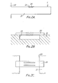
- FIG. 1A Two shapes for the beam structure of the invention are shown in outline in Figures 1A and B.
- That of Figure 1A is a strip (10) of piezoelectric material that has had two centrally located narrow slots (11T, B) cut into it parallel to but spaced either side of the strip long axis; the strip material between and outside the slots are the beams - the main beam (12) in the centre and the two counterbalance beams (13T, B) on either side.
- the three beams have at each end a common mounting (14L,R) which is contiguous with the strip end portions (15L,R) by which the strip is mounted in or on the device in which it is used.
- the strip of Figure 1B is a wider, longer version of that of Figure 1A with the addition of a neck (16L,R) of material separating each beam mounting 14L,R from the relevant strip end portion 15L,R.
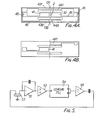
- Figures 2A, B and C show (in side elevation, part section and part plan respectively) a beam structure like that of Figure 1A mounted over a slot in a cantilever.
- the cantilever (21) is rigidly mounted at one end on a support (22), and moves up and down (as viewed) under the influence of force F.
- a slot or notch 23 is cut in the surface, and bridging that slot (and affixed to the cantilever / surface portions on either side) is an inventive beam structure (24). The details of this are shown more clearly in Figures 2B and C (the former shows how the beam structure 24 is free to flex).
- An alternative type of mounting arrangement employs a flexible frame such as that shown in Figure 3A, Forces applied at the ends of the frame (31) are coupled more-or-less directly into the beam structure (32) but no large forces are generated by differential thermal expansion.
- a flimsy structure of this kind would probably be most appropriate in an atmospheric pressure transducer, where one end of the frame is attached to a rigid mount (33) and the other is attached to a pressure diaphragm (34).
- the force produced by the pressure diaphragm is coupled into the beam structure by the magnification ratio given by the relative lengths of the lever arms (35,36), and provided that the cross piece (37) is relatively thin no large forces will be generated in the beam structure by thermal expansion.
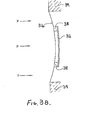
- FIG. 3B A simpler structure suitable for measuring pressures is shown in Figure 3B.
- a beam structure 32 (like those in Figures 1A and 1B, shown in side elevation), is attached via pillars (38) to a diaphragm 34 itself mounted on a support (39).
- the pillars 38 are preferably formed integrally with the diaphragm and/or with the beam structure 32. Applied pressure P acts to rotate the pillars, and therefore to extend the beam structure.
- each beam is driven and carries a pick-up electrode; the main beam 2 has a drive electrode (41) just to the left (as viewed) of its centre line and a pick-up electrode (42) just to the right, while each counterbalance beam (13T,B) has its own drive (43T,B) and pick-up (44T,B) electrode.
- Each of the drive and pick-up electrodes is connected via a thin conducting track (as 45) to a pad (as 46) to which in use a wire to the relevant circuitry is attached.
- the electrode layout of Figure 4B has a single drive electrode 41 driving the main beam and a single pick-up electrode 44T on the upper right (as viewed) counterbalance beam.
- the simple circuit shown schematically in Figure 5 can be used for this.
- the circuit consists of a charge amplifier (51) followed by an amplifier (52) with a band-pass characteristic chosen to reject frequencies outside the operating range and with a gain sufficient to ensure operation of the driving phase-locked loop integrated circuit chip (54 - here shown as a CD 4046).
- the band-pass characteristic of the amplifier 52 is necessary to ensure that the device does not oscillate either at higher harmonics or at some resonance frequency of the whole structure.
- the voltage-controlled oscillator in the phase-locked loop is centred on the middle of the operating frequency range, and locked to the beam mechanical resonance frequency by the amplifier's output signal.
- the square wave output from this oscillator is filtered (55) to remove the harmonics, and re-applied to the beam structure's drive electrode.
- the loop phase shift of the circuit is arranged so that the oscillator frequency is set at the resonance frequency of the beam structure and tracks the changes in resonance frequency produced by the applied strain.
- the oscillator output provides the strain-dependent output signal of the sensor.
Applications Claiming Priority (2)
| Application Number | Priority Date | Filing Date | Title |
|---|---|---|---|
| GB08315565A GB2141231B (en) | 1983-06-07 | 1983-06-07 | Force sensors |
| GB8315565 | 1983-06-07 |
Publications (3)
| Publication Number | Publication Date |
|---|---|
| EP0130705A2 true EP0130705A2 (de) | 1985-01-09 |
| EP0130705A3 EP0130705A3 (en) | 1986-02-26 |
| EP0130705B1 EP0130705B1 (de) | 1989-11-08 |
Family
ID=10543901
Family Applications (1)
| Application Number | Title | Priority Date | Filing Date |
|---|---|---|---|
| EP84303760A Expired EP0130705B1 (de) | 1983-06-07 | 1984-06-05 | Schwingstabstruktur für Kraft- oder Druckwandler mit piezoelektrischen Schwingstäben |
Country Status (5)
| Country | Link |
|---|---|
| US (1) | US4594898A (de) |
| EP (1) | EP0130705B1 (de) |
| JP (1) | JPS6069528A (de) |
| DE (1) | DE3480425D1 (de) |
| GB (1) | GB2141231B (de) |
Cited By (2)
| Publication number | Priority date | Publication date | Assignee | Title |
|---|---|---|---|---|
| GB2196120A (en) * | 1986-10-10 | 1988-04-20 | Gen Electric Co Plc | A resonant element force sensor in a housing affording temperature and pressure compensation |
| GB2215053A (en) * | 1988-02-13 | 1989-09-13 | Stc Plc | Electro-mechanical oscillating transducer devices |
Families Citing this family (31)
| Publication number | Priority date | Publication date | Assignee | Title |
|---|---|---|---|---|
| JPS6255136U (de) * | 1985-09-27 | 1987-04-06 | ||
| US4751849A (en) * | 1986-06-17 | 1988-06-21 | Paroscientific, Inc. | Force-sensitive resonator load cell |
| IL80550A0 (en) * | 1986-11-07 | 1987-02-27 | Israel Aircraft Ind Ltd | Resonant element force transducer for acceleration sensing |
| US4878385A (en) * | 1988-02-02 | 1989-11-07 | Fisher Controls International, Inc. | Differential pressure sensing apparatus |
| GB8806214D0 (en) * | 1988-03-16 | 1988-04-13 | Avery Ltd W & T | Vibrating force sensor |
| FR2638519B1 (fr) * | 1988-11-02 | 1990-12-28 | Asulab Sa | Dispositif de mesure d'une grandeur physique |
| FR2640045B1 (fr) * | 1988-12-02 | 1991-03-08 | Sagem | Transducteur force-frequence a poutres vibrantes et accelerometre pendulaire en comportant application |
| US5060526A (en) * | 1989-05-30 | 1991-10-29 | Schlumberger Industries, Inc. | Laminated semiconductor sensor with vibrating element |
| US5036715A (en) * | 1989-06-30 | 1991-08-06 | Richard Hanson | Cantilevered force sensing assembly utilizing one or two resonating force sensing devices |
| HU212353B (en) * | 1990-02-22 | 1996-06-28 | Istvan Almasi | Path-frequency signal transducer |
| FR2669426B1 (fr) * | 1990-11-16 | 1993-10-29 | Onera | Transducteur de force a poutre vibrante piezoelectrique pour capteur accelerometrique. |
| US5095763A (en) * | 1990-12-03 | 1992-03-17 | Delatorre Leroy C | Load-sensitive resonator beam transducer |
| US5201224A (en) * | 1991-05-03 | 1993-04-13 | Fmc Corporation | Apparatus and method for sensing unbalance force and location through frequency modulation |
| WO1993010428A1 (en) * | 1991-11-12 | 1993-05-27 | Masstech Scientific Pty. Ltd. | Force or load sensors |
| US5962786A (en) * | 1995-09-26 | 1999-10-05 | Onera (Office National D'eudes Et De Recheres Aerospatiales) | Monolithic accelerometric transducer |
| EP0852708B1 (de) * | 1995-09-29 | 2001-09-12 | International Business Machines Corporation | Mechanischer signalprozessor auf basis von mikromechanischen oszillatoren und intelligenten akustischen detektoren und darauf aufgebaute systeme |
| GB0116393D0 (en) * | 2001-07-05 | 2001-08-29 | Druck Ltd | Improved sensor |
| EP1590642B1 (de) * | 2003-02-05 | 2008-09-03 | Brunel University | Resonanzsensorbaugruppe |
| JP4359757B2 (ja) * | 2003-09-17 | 2009-11-04 | ソニー株式会社 | 情報表示装置 |
| US7032454B2 (en) * | 2004-03-05 | 2006-04-25 | Agilent Technologies, Inc. | Piezoelectric cantilever pressure sensor array |
| US7498728B2 (en) | 2006-06-21 | 2009-03-03 | Pressure Systems, Inc. | Vibrating beam force sensor of improved ruggedness and mountability |
| WO2008081181A1 (en) * | 2006-12-28 | 2008-07-10 | Highland Biosciences Limited | Biosensor |
| GB0716542D0 (en) * | 2007-08-24 | 2007-10-03 | Highland Biosciences Ltd | Endotoxin biosensor |
| DE102008037572A1 (de) | 2008-01-29 | 2009-08-06 | Werner Turck Gmbh & Co. Kg | Kraftsensor |
| JP5487672B2 (ja) * | 2009-03-27 | 2014-05-07 | パナソニック株式会社 | 物理量センサ |
| US20130201316A1 (en) | 2012-01-09 | 2013-08-08 | May Patents Ltd. | System and method for server based control |
| JP2014020785A (ja) * | 2012-07-12 | 2014-02-03 | Seiko Epson Corp | 圧力検出デバイス、電子機器、移動体 |
| US10580605B2 (en) | 2015-11-23 | 2020-03-03 | University Of Utah Research Foundation | Very low power microelectromechanical devices for the internet of everything |
| EP3652721A1 (de) | 2017-09-04 | 2020-05-20 | NNG Software Developing and Commercial LLC | Verfahren und vorrichtung zum sammeln und verwenden von sensordaten von einem fahrzeug |
| DE102017121347A1 (de) | 2017-09-14 | 2019-03-14 | Turck Holding Gmbh | Schlauchdrucksensor für eine Schlauchpumpenanordnung |
| CH718762A1 (de) * | 2021-06-23 | 2022-12-30 | Digi Sens Holding Ag | Schwingbrücke für einen Schwingsaitensensor und Schwingsaitensensor. |
Citations (2)
| Publication number | Priority date | Publication date | Assignee | Title |
|---|---|---|---|---|
| US3190129A (en) * | 1961-07-10 | 1965-06-22 | Bosch Arma Corp | Accelerometer and parts therefor |
| US3470400A (en) * | 1967-12-21 | 1969-09-30 | Singer General Precision | Single beam force transducer with integral mounting isolation |
Family Cites Families (8)
| Publication number | Priority date | Publication date | Assignee | Title |
|---|---|---|---|---|
| GB823847A (en) * | 1955-11-11 | 1959-11-18 | Ferranti Ltd | Improvements relating to transducers |
| GB1181515A (en) * | 1966-05-18 | 1970-02-18 | Solartron Electronic Group | Improvements in or relating to Force-Measuring Apparatus. |
| US4071838A (en) * | 1976-02-09 | 1978-01-31 | Diax Corporation | Solid state force transducer and method of making same |
| US4215570A (en) * | 1979-04-20 | 1980-08-05 | The United States Of America As Represented By The United States Department Of Energy | Miniature quartz resonator force transducer |
| JPS596370B2 (ja) * | 1979-05-11 | 1984-02-10 | 横河電機株式会社 | 力変換機構 |
| US4372173A (en) * | 1980-10-20 | 1983-02-08 | Quartex, Inc. | Resonator force transducer |
| US4446394A (en) * | 1981-09-14 | 1984-05-01 | The Singer Company | Linearizing mechanism for a vibrating beam force transducer |
| GB2115551B (en) * | 1982-02-09 | 1985-11-13 | Itt Ind Ltd | Load sensor |
-
1983
- 1983-06-07 GB GB08315565A patent/GB2141231B/en not_active Expired
-
1984
- 1984-06-05 EP EP84303760A patent/EP0130705B1/de not_active Expired
- 1984-06-05 DE DE8484303760T patent/DE3480425D1/de not_active Expired
- 1984-06-06 US US06/617,712 patent/US4594898A/en not_active Expired - Lifetime
- 1984-06-07 JP JP59117425A patent/JPS6069528A/ja active Granted
Patent Citations (2)
| Publication number | Priority date | Publication date | Assignee | Title |
|---|---|---|---|---|
| US3190129A (en) * | 1961-07-10 | 1965-06-22 | Bosch Arma Corp | Accelerometer and parts therefor |
| US3470400A (en) * | 1967-12-21 | 1969-09-30 | Singer General Precision | Single beam force transducer with integral mounting isolation |
Cited By (3)
| Publication number | Priority date | Publication date | Assignee | Title |
|---|---|---|---|---|
| GB2196120A (en) * | 1986-10-10 | 1988-04-20 | Gen Electric Co Plc | A resonant element force sensor in a housing affording temperature and pressure compensation |
| GB2215053A (en) * | 1988-02-13 | 1989-09-13 | Stc Plc | Electro-mechanical oscillating transducer devices |
| GB2215053B (en) * | 1988-02-13 | 1991-09-11 | Stc Plc | Transducer device |
Also Published As
| Publication number | Publication date |
|---|---|
| US4594898A (en) | 1986-06-17 |
| EP0130705A3 (en) | 1986-02-26 |
| EP0130705B1 (de) | 1989-11-08 |
| GB2141231B (en) | 1986-08-06 |
| DE3480425D1 (en) | 1989-12-14 |
| JPS6069528A (ja) | 1985-04-20 |
| GB8315565D0 (en) | 1983-07-13 |
| JPH053536B2 (de) | 1993-01-18 |
| GB2141231A (en) | 1984-12-12 |
Similar Documents
| Publication | Publication Date | Title |
|---|---|---|
| EP0130705B1 (de) | Schwingstabstruktur für Kraft- oder Druckwandler mit piezoelektrischen Schwingstäben | |
| US5005413A (en) | Accelerometer with coplanar push-pull force transducers | |
| US4306456A (en) | Elastic wave accelerometer | |
| US4215570A (en) | Miniature quartz resonator force transducer | |
| US4899587A (en) | Method for sensing rotation using vibrating piezoelectric elements | |
| USRE32931E (en) | Vibratory angular rate sensor system | |
| US4900971A (en) | Face shear mode quartz crystal resonator | |
| US4901586A (en) | Electrostatically driven dual vibrating beam force transducer | |
| US4524619A (en) | Vibratory angular rate sensor system | |
| US5260596A (en) | Monolithic circuit with integrated bulk structure resonator | |
| US4912990A (en) | Magnetically driven vibrating beam force transducer | |
| US4656383A (en) | Vibrating beam force transducer with single isolator spring | |
| US4676104A (en) | Surface skimming bulk acoustic wave accelerometer | |
| US4139793A (en) | Integral resonant support arms for piezoelectric microresonators | |
| US20110174075A1 (en) | Acceleration sensor and acceleration detecting apparatus | |
| JPH0384467A (ja) | 湾曲振動ビームのある加速度計センサー | |
| US6453744B2 (en) | Low radiation capture cross-section electrode material for prompt radiation environments | |
| CA2233374C (en) | Monolithic accelerometric transducer | |
| US6803698B2 (en) | Acceleration sensor | |
| US4199990A (en) | Elastic surface wave accelerometer | |
| JP3908713B2 (ja) | 原子間力顕微鏡用力方位センサ付カンチレバー | |
| US6786095B2 (en) | Acceleration sensor | |
| US6672160B2 (en) | Acceleration sensor | |
| EP0309567A4 (en) | Force sensing vibrating beam resonator | |
| JPH0643179A (ja) | 加速度センサ及び該センサの製造方法 |
Legal Events
| Date | Code | Title | Description |
|---|---|---|---|
| PUAI | Public reference made under article 153(3) epc to a published international application that has entered the european phase |
Free format text: ORIGINAL CODE: 0009012 |
|
| AK | Designated contracting states |
Designated state(s): DE FR NL |
|
| PUAL | Search report despatched |
Free format text: ORIGINAL CODE: 0009013 |
|
| AK | Designated contracting states |
Designated state(s): DE FR NL |
|
| 17P | Request for examination filed |
Effective date: 19860219 |
|
| 17Q | First examination report despatched |
Effective date: 19870506 |
|
| GRAA | (expected) grant |
Free format text: ORIGINAL CODE: 0009210 |
|
| AK | Designated contracting states |
Kind code of ref document: B1 Designated state(s): DE FR NL |
|
| REF | Corresponds to: |
Ref document number: 3480425 Country of ref document: DE Date of ref document: 19891214 |
|
| ET | Fr: translation filed | ||
| PLBE | No opposition filed within time limit |
Free format text: ORIGINAL CODE: 0009261 |
|
| STAA | Information on the status of an ep patent application or granted ep patent |
Free format text: STATUS: NO OPPOSITION FILED WITHIN TIME LIMIT |
|
| 26N | No opposition filed | ||
| PGFP | Annual fee paid to national office [announced via postgrant information from national office to epo] |
Ref country code: FR Payment date: 20030626 Year of fee payment: 20 |
|
| PGFP | Annual fee paid to national office [announced via postgrant information from national office to epo] |
Ref country code: NL Payment date: 20030630 Year of fee payment: 20 |
|
| PGFP | Annual fee paid to national office [announced via postgrant information from national office to epo] |
Ref country code: DE Payment date: 20030827 Year of fee payment: 20 |
|
| PG25 | Lapsed in a contracting state [announced via postgrant information from national office to epo] |
Ref country code: NL Free format text: LAPSE BECAUSE OF EXPIRATION OF PROTECTION Effective date: 20040605 |
|
| NLV7 | Nl: ceased due to reaching the maximum lifetime of a patent |
Effective date: 20040605 |