EP0129924B1 - Process for operating and controlling compound needles, and stitch-forming cams suitable for carrying out this process - Google Patents
Process for operating and controlling compound needles, and stitch-forming cams suitable for carrying out this process Download PDFInfo
- Publication number
- EP0129924B1 EP0129924B1 EP84200803A EP84200803A EP0129924B1 EP 0129924 B1 EP0129924 B1 EP 0129924B1 EP 84200803 A EP84200803 A EP 84200803A EP 84200803 A EP84200803 A EP 84200803A EP 0129924 B1 EP0129924 B1 EP 0129924B1
- Authority
- EP
- European Patent Office
- Prior art keywords
- needle
- slider
- slope
- track
- descent
- Prior art date
- Legal status (The legal status is an assumption and is not a legal conclusion. Google has not performed a legal analysis and makes no representation as to the accuracy of the status listed.)
- Expired
Links
- 150000001875 compounds Chemical class 0.000 title claims description 34
- 238000000034 method Methods 0.000 title claims description 17
- 230000008569 process Effects 0.000 title claims description 14
- 238000009940 knitting Methods 0.000 claims description 16
- 230000009471 action Effects 0.000 claims description 4
- 230000007704 transition Effects 0.000 description 4
- 238000012360 testing method Methods 0.000 description 3
- 230000015572 biosynthetic process Effects 0.000 description 2
- 238000006073 displacement reaction Methods 0.000 description 2
- 230000000694 effects Effects 0.000 description 2
- 238000012552 review Methods 0.000 description 2
- 238000010521 absorption reaction Methods 0.000 description 1
- 238000013459 approach Methods 0.000 description 1
- 230000001934 delay Effects 0.000 description 1
- 238000011161 development Methods 0.000 description 1
- 230000007774 longterm Effects 0.000 description 1
- 238000009877 rendering Methods 0.000 description 1
- 230000001052 transient effect Effects 0.000 description 1
- 238000011144 upstream manufacturing Methods 0.000 description 1
Images

Classifications
-
- D—TEXTILES; PAPER
- D04—BRAIDING; LACE-MAKING; KNITTING; TRIMMINGS; NON-WOVEN FABRICS
- D04B—KNITTING
- D04B35/00—Details of, or auxiliary devices incorporated in, knitting machines, not otherwise provided for
- D04B35/02—Knitting tools or instruments not provided for in group D04B15/00 or D04B27/00
- D04B35/06—Sliding-tongue needles
-
- D—TEXTILES; PAPER
- D04—BRAIDING; LACE-MAKING; KNITTING; TRIMMINGS; NON-WOVEN FABRICS
- D04B—KNITTING
- D04B15/00—Details of, or auxiliary devices incorporated in, weft knitting machines, restricted to machines of this kind
- D04B15/32—Cam systems or assemblies for operating knitting instruments
Definitions
- This invention concerns a process for operating and controlling compound needles.
- the invention also concerns improvements to stitch-forming cams in cylindrical knitting machines; to be more exact, the invention concerns improvements applied to stitch-forming cams and suitable for enabling compound needles to be operated and controlled according to the process.
- the invention concerns stitch-forming cams in circular knitting machines which employs the foregoing improvements.
- the invention refers to cams positioned on the cylinder of circular knitting machines.
- the invention refers to high-speed or very high-speed circular knitting machines, such as are suitable for working at 800-1000 revolutions per minute or more with 4" cylinders or the like.
- GB 1,571,017 (DE-A-2.705.605) in the name of TIPPSA is known which proposes compound needles and a lay-out of cams to control these needles.
- FR 1.573.866 discloses a circular knitting machine with compound needles; in this machine both the needle and the slider are controlled by cams.
- GB 2,020,705 A is known and discloses a circular knitting machine that employs compound needles. This invention dwells in particular on the needles used and on the methods for forming stitches but does not provide information in depth about the structure of the outfit of cams intended to guide the needles.
- the compound needles employed consist, moreover, of three parts, one of which is a closure part that cannot move axially to the cylinder and that controls the travel of the slider element.
- the structure of the needles is complicated and entails considerable sizes and frictions, thus rendering the invention unsuitable for use with high and very high speeds.
- US 3,828,582 discloses compound needles in which the slider element has a lateral controlling curvature, and also discloses an arrangement of cams intended to operate and control the compound needles.
- DE-A-2.705.605 envisages that the descent of the needles takes place along two successive slopes having differentiated descent inclinations, the second slope being steeper.
- a first known method for controlling this position is to embody a curvature of the slider so as to create a given friction between the slider and the needle bed trick.
- the slider should not go beyond its theoretical position and should not undergo dynamic stresses greater than those permissible, or at any rate stresses which might reduce its life considerably.
- the travel of the needle in relation to the slider is arranged in such a way that the distance between the upper point of the needle lifter means positioned downstream from the abutment cams and the lower position of the counter-cam cooperating with the abutment cam is such as to be substantially the same as the reciprocal travel as between the needle and the slider.
- Two abutment positions are located as between the needle element and the slider element.
- the possible reciprocal travel of these elements is greater than, or the same as, the amount by which the needle has to be lifted so to engage the yarn. In this way a tuck stitch is obtained.
- the cam which abuts against the needles and which normally comprises in its lower track a first gentle descending approach slope and a final very steep abutment slope has to be such that the beginning of the steep abutment slope will lie in a position lower than the upper position of the needle butt leaving the tuck stitch leveller tract formed on the needle lifter means.
- the needle butt will meet the gentle descent slope, which is less inclined and therefore causes less stress, before being subjected to a sudden sharp descent.
- the sharp descent slope can also be rounded progressively to join the gentle descent slope located immediately upstream and can be progressively and variably inclined over an ample tract.
- transition point shall mean not only that point but also the neighbourhood of that point.
- the applicants have envisaged as cooperating with the stitch-forming cam at least one cam to level the upper position of the slider leaving the ascent means which lift the needle.
- the applicants have embodied an upper sliding surface for the butt of the slider, this surface being coordinated with the lower position of abutment of the needles.
- the applicants have embodied an advantageous upper conformation of the abutment cam such as to be able to discharge resiliently the dynamic tensions produced in the slider itself.
- a deceleration track is envisaged on the upper flank of the needle-abutment cam in a position coordinated with the bottom dead centre point of that cam.
- This deceleration track has its lowest point lying at such a distance from the bottom dead centre point as is substantially the same as, or very little less than, the inner distance between the two butts in their positions spaced farthest apart, that is, their positions when the compound needle is closed.
- this deceleration track has the effect that, when the needle reaches the bottom dead centre point, the slider has available a further given descent travel which allows it to absorb dynamically the forces acting upon it.
- Such means can be embodied as an additional track, for instance, which acts on the slider butt.
- This invention is therefore obtained with a process for operating and controlling compound needles of a type having a reciprocal travel of needle and slider restricted by appropriate abutment surfaces on a needle and slider, which process comprises the lifting of the needle by an amount enough to engage the yarn but less than the reciprocal needle/slider travel, and also the descent of the needle, the descent of the needle taking place along at least two successive slopes in a track with different descent inclinations of which the second slope is steeper, and is characterized by comprising also, before such descent of the needle, the selective lifting of the needle by an amount such as to bring, through the action of abutment between the needle and. slider, the upper end of the slider above the plane of knock-over of the sinkers, the recall of the slider by the needle beginning before the needle itself is brought down again by the second slope.
- the invention is also obtained with stitch-forming cams in circular knitting machines, which cams are suitable for enabling compound needles to be operated and controlled according to the foregoing process and comprise at least track means for reascent of the needles, abutment cam means including gentle slope means for descent of the needles and steep abutment slope means, counter-cam means to establish the bottom dead centre point for the needles, upper track means which control the travel of the slider butt from below, and an upper leveller cam means which controls the travel of the slider butt from above, the stitch-forming cams being characterized by comprising track means to decelerate the slider butt in a position coordinated with at least the end part of the steep slope that abuts against the needle, the track means being obtained in cooperation with the upper track means, the inclination of the controlled descent slope of the deceleration track being less than the inclination of the steep slope that abuts against the needle.
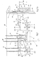
- a compound needle 10 with a hook 28 has to cooperate with the plane of the knock-over of sinkers 38 according to well- determined geometric functions so as to be able to form the desired stitches with the form and characteristics required.
- the compound needle 10 cooperates with and on the periphery of a cylinder 34 in normal needle bed tricks 33 as used with normal needles.
- Figs. 1 show the path of a needle 11, a butt 30 of which is firstly engaged by a lifting track 16 present on the top of needle lifter means 15.
- a pusher or selector means 40 is included in correspondence with the straight tract 17 and has the task of lifting or not lifting the butt 30 above the tuck stitch tract 17, depending on the type of stitch to be produced.
- the invention advantageously envisages the tract 17 plus the thickness of the butt 30 as being higher than a transition point 21.
- the needle 11 continues its trajectory, leaving the lifting track 16 and engaging the descent track 20 in coincidence with the gentle slope 120, which has a not very steep inclination.
- the slope 120 may possibly develop, as shown, in two or more rounded tracts so as not to speed up the needle 11 too much and so as not to transmit excessive stresses to the needle 11; or else the slope 120 may have a gradually variable inclination.
- the descent track 20 has a steep slope 220 to abut against the needle 11.
- the needle 11 After the slope 220 the needle 11, having passed a bottom dead centre point 18 located on a counter-cam 14, is lifted once again and sent along a successive ascent track 16 on successive needle lifter means 15.
- the protrusions 35-36 abut alternatively against the projection 37 of the slider 12 and regulate its to-and-fro travel.
- the slider 12 itself is provided with a butt 29.
- This butt 29 is controlled from below by a track 22 located on the upper flank of an abutment cam 13, and its travel is restricted from above by an upper leveller cam 31 having a straight development.
- the butt 29 of the slider 12 meets the upper leveller cam 31, so that the upper position of the slider 12 is controlled during descent of the needle 11.
- the needle 11 engages the projection 37 of the slider 12 with its upper protrusion 35. This causes the slider 12 to descend together with the needle 11.
- a deceleration track 25 is envisaged for the purpose of eliminating this shortcoming by braking the impact of the butt 29 against the track 22.
- the track 25 has a controlled descent slope 125 with an inclination 27 and a controlled reascent slope 225.
- the deceleration track 25 has the purpose of braking the travel of the slider 12 and of causing a somewhat gentle inversion of the movement of the slider 12 simultaneously with inversion of the movement of the needle 11. In this way a sudden deceleration of the slider 12 is obviated.
- 24 is the distance between the lower edge of the butt 29 and the upper edge of the butt 30. This distance 24 is substantially the same as, or a little greater than, the distance between the bottom of the track 25 and the lower end 19 of the track 220.
- the present applicants have found by tests that the inclination 27 of the tract 125 should be less than the inclination 26 of the steep slope 220 that abuts against the needle 11.
- reascent tract 225 which permits the slider 12 to reascend gently and to keep its relative position so as to avoid a collision with the needle 11 moving on the profile 17.
- the figures also show the greatest inner distance 23 between the projection 37 on the slider 12 and the upper protrusion 35 on the needle 11. This distance 23 is therefore the free travel between the needle 11 and slider 12.
- the invention envisages that the distance 23 will be substantially the same as the distance between the bottom dead centre point 18 and the straight tract 17 which follows the needle lifting track 16. In this way the slider 12 cannot begin to reascend when thrust by the needle 11 until the needle 11 has reached the end of the lifting track 16.
- the distance 39 shown in the figures between the upper leveller cam 31 and the transition point 21 is envisaged in the invention as being greater than the greatest distance 124 between the upper edge of the butt 29 and the upper edge of the butt 30.
- Figs. 2 show a variant in which an intermediate leveller cam 32 for special types of stitch is envisaged for the purpose of avoiding the tugging of the slider 12.
- This intermediate leveller cam 32 can be made resiliently sprung advantageously, as is shown in the figures. The purpose of this is to avoid damage or breakage in the event of impact of the slider butt 29 against the leveller cam 32.
- a pre-leveller cam 41 may be envisaged so as to prevent the slider 12 being pulled up by the needle 11 before the required tract. This pulling can occur through friction in coincidence with the reascent of the needle 11 along the lifting track 16.
- the pre-leveller cam 41 be rounded so as to join the upper leveller cam 31, as shown in the figures.
- the leveller cam 31 and pre-leveller cam 41 may possibly be embodied in one single piece.
- a track 45 to launch the slider 12, as shown with lines of dashes in.Fig. 2a.
- This track 45 has the task of actuating the descent of the slider 12 before the latter is engaged by the needle 11 descending speedily.
Landscapes
- Engineering & Computer Science (AREA)
- Textile Engineering (AREA)
- Knitting Machines (AREA)
Description
- This invention concerns a process for operating and controlling compound needles.
- The invention also concerns improvements to stitch-forming cams in cylindrical knitting machines; to be more exact, the invention concerns improvements applied to stitch-forming cams and suitable for enabling compound needles to be operated and controlled according to the process.
- Moreover, the invention concerns stitch-forming cams in circular knitting machines which employs the foregoing improvements.
- In particular the invention refers to cams positioned on the cylinder of circular knitting machines.
- To be more specific, the invention refers to high-speed or very high-speed circular knitting machines, such as are suitable for working at 800-1000 revolutions per minute or more with 4" cylinders or the like.
- It is known that circular knitting machines entail dynamic problems regarding movement of the needles, the problems involving very heavy stresses in the needles themselves.
- Compound needles of various types and conformations or indeed compound needles of the types disclosed in the state of the art given hereinafter are known.
- Various methods for controlling and operating these compound needles by means of cams are known, as also are various arrangements of cams intended to perform such operating and controlling.
- For instance, GB 1,571,017 (DE-A-2.705.605) in the name of TIPPSA is known which proposes compound needles and a lay-out of cams to control these needles.
- This patent does not envisage the possibility of working with tuck stitches nor does it avoid the throwing of the slider element in both directions by the needle element when the machine is working at high speed.
- DE-A-2.320.789 in the name of TERROT is also known and discloses compound needles actuated by cams. The nature of the system of cams employed, and in particular, the steepness of their tracks and the absence of rounded corners make this invention unsuitable for high speeds. Tracks to control the travel of the slider element are shown.
- DE-A-2.908.022 (TERROT) concerns mainly the formation of compound needles. In this invention too the control cams seem unsuitable for use at high speeds.
- FR 1.573.866 (MORAT) discloses a circular knitting machine with compound needles; in this machine both the needle and the slider are controlled by cams.
- GB 2,020,705 A is known and discloses a circular knitting machine that employs compound needles. This invention dwells in particular on the needles used and on the methods for forming stitches but does not provide information in depth about the structure of the outfit of cams intended to guide the needles.
- The compound needles employed consist, moreover, of three parts, one of which is a closure part that cannot move axially to the cylinder and that controls the travel of the slider element.
- The structure of the needles is complicated and entails considerable sizes and frictions, thus rendering the invention unsuitable for use with high and very high speeds.
- US 3,828,582 discloses compound needles in which the slider element has a lateral controlling curvature, and also discloses an arrangement of cams intended to operate and control the compound needles.
- DE-A-2.705.605 envisages that the descent of the needles takes place along two successive slopes having differentiated descent inclinations, the second slope being steeper.
- Problems linked to compound needles are normally well known. These problems are already obvious in traditional compound needles at the restricted working speeds now known, such working speeds being restricted either as regards linear displacement or as regards lengthwise displacement.
- It is also known that various compound needles have been specifically designed essentially for linear machines, in which centrifugal force is practically non-existent, or for large diameter circular machines, in which centrifugal force is of a low value owing to their low speed.
- In high-speed and very high-speed cylindrical machines all the stresses are strongly displayed and are translated into an exceptional dynamic pressure on every component of a compound needle.
- The present applicants have therefore found it necessary to make possible a considerable life for the compound needles designed and embodied by themselves and have thus had to review in depth the generating concepts of the abutment cams, the purpose of this being to make the traditional abutment cams, and also the abutment cams patented and protected by the applicants, compatible with employment of new compound needles.
- One of the most evident problems regarding the application of compound needles to high-speed and very high-speed circular knitting machines is linked to the constant control of the position of the slider element in relation to the needle element.
- A first known method for controlling this position is to embody a curvature of the slider so as to create a given friction between the slider and the needle bed trick.
- This curvature, however,' above all during inversions of lengthwise movement, is not enough to control the slider actively in relation to the needle element.
- It therefore became necessary to tackle the problem of how to be able to control the position of the slider in relation to the needle continously and at all transient times.
- In fact it is desirable that the slider should not go beyond its theoretical position and should not undergo dynamic stresses greater than those permissible, or at any rate stresses which might reduce its life considerably.
- To obviate this, the applicants have not only had to review all the geometric components of the cams and counter-cams but have also had to re-think the abutment cam completely. The purpose of this is to make compatible this new embodiment of compound needles and thus to extend the already great possibilities of perfect control and rationalization of the formation of stitches by abutment cams and in particular by the abutment cams designed, tested and, at due times, patented by the present applicants themselves.
- According to the invention the travel of the needle in relation to the slider is arranged in such a way that the distance between the upper point of the needle lifter means positioned downstream from the abutment cams and the lower position of the counter-cam cooperating with the abutment cam is such as to be substantially the same as the reciprocal travel as between the needle and the slider.
- Two abutment positions are located as between the needle element and the slider element.
- The possible reciprocal travel of these elements is greater than, or the same as, the amount by which the needle has to be lifted so to engage the yarn. In this way a tuck stitch is obtained.
- Furthermore, the applicants have found that the cam which abuts against the needles and which normally comprises in its lower track a first gentle descending approach slope and a final very steep abutment slope has to be such that the beginning of the steep abutment slope will lie in a position lower than the upper position of the needle butt leaving the tuck stitch leveller tract formed on the needle lifter means.
- In this way the needle butt will meet the gentle descent slope, which is less inclined and therefore causes less stress, before being subjected to a sudden sharp descent.
- The sharp descent slope can also be rounded progressively to join the gentle descent slope located immediately upstream and can be progressively and variably inclined over an ample tract.
- In such a case the applicants have found by tests that the beginning of the steep slope can be deemed to be the neighbourhood of the point where the inclination of the slope exceeds 20°.
- Hereinafter the words "transition point" shall mean not only that point but also the neighbourhood of that point.
- Moreover, the applicants have found that, so as to ensure a long working life for the compound needle, it is necessary to be able to ensure a constant control of the position of the slider in relation to the needle.
- This is necessary above all after a given period of working during which the friction and consequent reciprocal wear have made less rigid the control of the position of the slider in the trick by means of friction.
- To obviate this drawback, the applicants have envisaged as cooperating with the stitch-forming cam at least one cam to level the upper position of the slider leaving the ascent means which lift the needle.
- Furthermore, the applicants have found that the dynamic stresses applied to the slider during abutment are such as to have a considerable effect on the life of the slider itself.
- To prevent this, the applicants have embodied an upper sliding surface for the butt of the slider, this surface being coordinated with the lower position of abutment of the needles.
- In particular the applicants have embodied an advantageous upper conformation of the abutment cam such as to be able to discharge resiliently the dynamic tensions produced in the slider itself.
- According to this embodiment a deceleration track is envisaged on the upper flank of the needle-abutment cam in a position coordinated with the bottom dead centre point of that cam.
- This deceleration track has its lowest point lying at such a distance from the bottom dead centre point as is substantially the same as, or very little less than, the inner distance between the two butts in their positions spaced farthest apart, that is, their positions when the compound needle is closed.
- The inclusion of this deceleration track has the effect that, when the needle reaches the bottom dead centre point, the slider has available a further given descent travel which allows it to absorb dynamically the forces acting upon it.
- Moreover, the applicants have studied and found that such dynamic absorption is advantageous if the steep descent slope of the needle lies at an angle of 820° to the descent slope of the slider.
- This means that the descent slope of the deceleration track delays the descent of the slider and thus absorbs a given dynamic component of the slider gradually.
- Immediately afterwards the slider butt meets a reascent slope, which has the purpose of keeping the relative position of the slider unchanged even when the stem of the needle is lifted on the reascent track, thus avoiding an impact between the needle and the slider during ascent.
- Moreover, so as to avoid a sharp recall of the slider by the needle when the latter descends, such recall has to take place before the needle butt meets the steep descent slope.
- This is obtained by arranging that the distance between the profile for the upper levelling of the position of the slider and the beginning of the steep slope is greater than the maximum distance between the inside of the needle butt and the outside of the slider butt as permitted by the reciprocal needle/slider travel.
- In this way the recall of the slider by the needle takes place advantageously before the needle itself is lowered sharply by the steep descent slope.
- The result is a more gentle recall of the slider, which is also already in contact with the needle when the latter is engaged by the steep descent slope, thereby obviating an impact between the needle and slider in correspondence with that slope.
- According to a variant it is possible to envisage means to launch the slider, such means having the function of actuating the descent of the slider actively before the latter is engaged by the descending needle. Such launching means can be embodied as an additional track, for instance, which acts on the slider butt.
- This invention is therefore obtained with a process for operating and controlling compound needles of a type having a reciprocal travel of needle and slider restricted by appropriate abutment surfaces on a needle and slider, which process comprises the lifting of the needle by an amount enough to engage the yarn but less than the reciprocal needle/slider travel, and also the descent of the needle, the descent of the needle taking place along at least two successive slopes in a track with different descent inclinations of which the second slope is steeper, and is characterized by comprising also, before such descent of the needle, the selective lifting of the needle by an amount such as to bring, through the action of abutment between the needle and. slider, the upper end of the slider above the plane of knock-over of the sinkers, the recall of the slider by the needle beginning before the needle itself is brought down again by the second slope.
- The invention is also obtained with stitch-forming cams in circular knitting machines, which cams are suitable for enabling compound needles to be operated and controlled according to the foregoing process and comprise at least track means for reascent of the needles, abutment cam means including gentle slope means for descent of the needles and steep abutment slope means, counter-cam means to establish the bottom dead centre point for the needles, upper track means which control the travel of the slider butt from below, and an upper leveller cam means which controls the travel of the slider butt from above, the stitch-forming cams being characterized by comprising track means to decelerate the slider butt in a position coordinated with at least the end part of the steep slope that abuts against the needle, the track means being obtained in cooperation with the upper track means, the inclination of the controlled descent slope of the deceleration track being less than the inclination of the steep slope that abuts against the needle.
- We shall describe hereinafter as a non- restrictive example two preferred embodiments of the invention with the help of the attached figures, in which:-
- Figs. 1 show a first preferred embodiment of the invention;
- Figs. 2 give a variant of the invention.
- In the figures a
compound needle 10 with ahook 28 has to cooperate with the plane of the knock-over ofsinkers 38 according to well- determined geometric functions so as to be able to form the desired stitches with the form and characteristics required. - According to the invention the
compound needle 10 cooperates with and on the periphery of acylinder 34 in normalneedle bed tricks 33 as used with normal needles. - This means that the overall dimensions of the compound needle of the invention remain within the normal dimensions of a traditional needle.
- In this way it is possible to work with a compound needle or normal needle in circular knitting machines, depending on the type of stitch, without any need to replace the cylinder itself.
- Figs. 1 show the path of a
needle 11, abutt 30 of which is firstly engaged by a liftingtrack 16 present on the top of needle lifter means 15. - After the
lifting track 16, astraight tract 17 corresponding to a tuck stitch is present in the needle lifter means 15. - A pusher or selector means 40 is included in correspondence with the
straight tract 17 and has the task of lifting or not lifting thebutt 30 above thetuck stitch tract 17, depending on the type of stitch to be produced. - The invention advantageously envisages the
tract 17 plus the thickness of thebutt 30 as being higher than atransition point 21. - The applicants have found by tests that with such an arrangement the contact of the
butt 30 with atrack 20 takes place before thetransition point 21, so that the beginning of the return of theneedle 11 occurs on agentle descent slope 120 and is therefore smoother. - The
needle 11 continues its trajectory, leaving the liftingtrack 16 and engaging thedescent track 20 in coincidence with thegentle slope 120, which has a not very steep inclination. - The
slope 120 may possibly develop, as shown, in two or more rounded tracts so as not to speed up theneedle 11 too much and so as not to transmit excessive stresses to theneedle 11; or else theslope 120 may have a gradually variable inclination. - Immediately afterwards the
descent track 20 has asteep slope 220 to abut against theneedle 11. - After the
slope 220 theneedle 11, having passed a bottomdead centre point 18 located on a counter-cam 14, is lifted once again and sent along asuccessive ascent track 16 on successive needle lifter means 15. - The guiding of the
butt 30 of theneedle 11 is obtained with the above tracks. Instead, theslider 12 is guided by means of aprojection 37 which cooperates alternatively with anupper protrusion 35 andlower protrusion 36 jutting from theneedle 11. - The protrusions 35-36 abut alternatively against the
projection 37 of theslider 12 and regulate its to-and-fro travel. - Furthermore, so as to avoid excessive movements of the
slider 12 and to ensure that it is controlled during its closure phase, namely when the slider is in the position where thebutt 30 of theneedle 11 engages thegentle slope 120 of thedescent track 20, theslider 12 itself is provided with abutt 29. - This
butt 29 is controlled from below by atrack 22 located on the upper flank of anabutment cam 13, and its travel is restricted from above by anupper leveller cam 31 having a straight development. - The
butt 29 of theslider 12 meets theupper leveller cam 31, so that the upper position of theslider 12 is controlled during descent of theneedle 11. - At a given point on its descent, the
needle 11 engages theprojection 37 of theslider 12 with itsupper protrusion 35. This causes theslider 12 to descend together with theneedle 11. - As soon as the
needle 11 reaches the bottomdead centre point 18, that is to say, when it coincides with aninversion point 19 of thelower track 20 comprised on theabutment cam 13, if theupper track 22 of theabutment cam 13 were flat, thebutt 29 of theslider 12 would collide violently against thetrack 22. In the long term this would create serious problems for the strength of theslider 12 itself. - A
deceleration track 25 is envisaged for the purpose of eliminating this shortcoming by braking the impact of thebutt 29 against thetrack 22. - The
track 25 has a controlleddescent slope 125 with aninclination 27 and a controlledreascent slope 225. - The
deceleration track 25 has the purpose of braking the travel of theslider 12 and of causing a somewhat gentle inversion of the movement of theslider 12 simultaneously with inversion of the movement of theneedle 11. In this way a sudden deceleration of theslider 12 is obviated. - In the figures, 24 is the distance between the lower edge of the
butt 29 and the upper edge of thebutt 30. Thisdistance 24 is substantially the same as, or a little greater than, the distance between the bottom of thetrack 25 and thelower end 19 of thetrack 220. - When the
butt 30 is at the bottomdead centre point 18, thebutt 29 and therefore theslider 12 have still available a given tract of travel so that their motion can be braked within thedeceleration track 25. This is advantageous for the working life of theslider 12 andneedle 11. - So as to carry out this deceleration as effectively as possible, the present applicants have found by tests that the
inclination 27 of thetract 125 should be less than theinclination 26 of thesteep slope 220 that abuts against theneedle 11. - The applicants have found in particular that the greatest efficiency of deceleration is obtained when the difference between the two
inclinations - Immediately afterwards and coinciding with the reascent of the
needle 11 caused by the counter-cam 14, there is comprised in the track 25 areascent tract 225, which permits theslider 12 to reascend gently and to keep its relative position so as to avoid a collision with theneedle 11 moving on theprofile 17. - The figures also show the greatest
inner distance 23 between theprojection 37 on theslider 12 and theupper protrusion 35 on theneedle 11. Thisdistance 23 is therefore the free travel between theneedle 11 andslider 12. - The invention envisages that the
distance 23 will be substantially the same as the distance between the bottomdead centre point 18 and thestraight tract 17 which follows theneedle lifting track 16. In this way theslider 12 cannot begin to reascend when thrust by theneedle 11 until theneedle 11 has reached the end of the liftingtrack 16. - The
distance 39 shown in the figures between theupper leveller cam 31 and thetransition point 21 is envisaged in the invention as being greater than thegreatest distance 124 between the upper edge of thebutt 29 and the upper edge of thebutt 30. - In this way the recall of the
slider 12 by theneedle 11 by means of the action of theprotrusion 35 against theprojection 37 takes place before theneedle 11 itself engages thesteep descent slope 220. - Indeed, in this way a sharp tug of a thrusting type applied to the
slider 12 by theneedle 11 by means of an impact of theprojection 37 against theupper protrusion 35 is avoided, for with such an impact theprojection 37 would undergo an excessively violent downwards thrust. - Instead, in this way the
projection 37 andprotrusion 35 engage each other before thebutt 30 is engaged and is thrust downwards by theslope 220. - Sharp actuation of the
slider 12, which would lead to serious shortcomings in thecompound needle 10 in a short time with occurrence of wear or possibility of breakage, is thus obviated. - Figs. 2 show a variant in which an
intermediate leveller cam 32 for special types of stitch is envisaged for the purpose of avoiding the tugging of theslider 12. - This
intermediate leveller cam 32 can be made resiliently sprung advantageously, as is shown in the figures. The purpose of this is to avoid damage or breakage in the event of impact of theslider butt 29 against theleveller cam 32. - Coordinated action of the
upper leveller cam 31 andintermediate leveller cam 32 leads to the position of theslider 12 being kept constant until just before the recall of theslider 12 by theneedle 11 in coincidence with the end portion of thegentle descent slope 120. - According to another variant shown in Figs. 2 also, a
pre-leveller cam 41 may be envisaged so as to prevent theslider 12 being pulled up by theneedle 11 before the required tract. This pulling can occur through friction in coincidence with the reascent of theneedle 11 along the liftingtrack 16. - The
pre-leveller cam 41 be rounded so as to join theupper leveller cam 31, as shown in the figures. - The
leveller cam 31 andpre-leveller cam 41 may possibly be embodied in one single piece. - According to a further variant it is possible to envisage a
track 45 to launch theslider 12, as shown with lines of dashes in.Fig. 2a. Thistrack 45 has the task of actuating the descent of theslider 12 before the latter is engaged by theneedle 11 descending speedily. - In this way it is possible to obviate impacts between
needle 11 andslider 12 during the steep descent of theneedle 11.
Claims (11)
Applications Claiming Priority (2)
| Application Number | Priority Date | Filing Date | Title |
|---|---|---|---|
| IT83407/83A IT1218730B (en) | 1983-06-27 | 1983-06-27 | PROCEDURE FOR THE COMMAND AND CONTROL OF PISTON NEEDLES, IMPROVEMENTS ON THE CAMS MESH TRAINING SUITABLE TO CARRY OUT SUCH PROCEDURE AND MACHINES FOR MESH TRAINING SO PERFECTED |
| IT8340783 | 1983-06-27 |
Publications (2)
| Publication Number | Publication Date |
|---|---|
| EP0129924A1 EP0129924A1 (en) | 1985-01-02 |
| EP0129924B1 true EP0129924B1 (en) | 1987-12-23 |
Family
ID=11321427
Family Applications (1)
| Application Number | Title | Priority Date | Filing Date |
|---|---|---|---|
| EP84200803A Expired EP0129924B1 (en) | 1983-06-27 | 1984-06-06 | Process for operating and controlling compound needles, and stitch-forming cams suitable for carrying out this process |
Country Status (5)
| Country | Link |
|---|---|
| US (1) | US4674301A (en) |
| EP (1) | EP0129924B1 (en) |
| JP (1) | JPS6045652A (en) |
| DE (1) | DE3468243D1 (en) |
| IT (1) | IT1218730B (en) |
Families Citing this family (3)
| Publication number | Priority date | Publication date | Assignee | Title |
|---|---|---|---|---|
| CN101812768B (en) * | 2010-04-23 | 2012-05-23 | 浙江汇力达精密机械有限公司 | Knitting cam needle-running track of circular knitting machine and machining method |
| WO2020250075A1 (en) * | 2019-06-11 | 2020-12-17 | Santoni S.P.A. | A circular knitting machine and a method for moving the needles of a circular knitting machine |
| CN112846549B (en) * | 2021-01-29 | 2022-12-30 | 贝隆精密科技股份有限公司 | Feeding and discharging pushing mechanism of laser marking device |
Family Cites Families (7)
| Publication number | Priority date | Publication date | Assignee | Title |
|---|---|---|---|---|
| US1391033A (en) * | 1919-04-12 | 1921-09-20 | Spartan Needle Company | Knitting-needle unit |
| DE1635844B2 (en) * | 1967-02-14 | 1976-05-06 | Sulzer Morat GmbH, 7026 Bcmlanden | PATTERN DEVICE ON A KNITTING MACHINE WITH TWO-PIECE NEEDLES |
| DE2245731A1 (en) * | 1972-09-18 | 1974-03-28 | Mayer & Cie Maschinenfabrik | Latch needle for circular knitters - with slide held by friction in needle bed guide |
| DE2320789A1 (en) * | 1973-04-25 | 1974-11-07 | Terrot Soehne & Co C | SLIDER NEEDLE FOR CIRCULAR KNITTING MACHINES |
| DE2705605C3 (en) * | 1976-03-05 | 1981-10-22 | Tecnología Industrial, Proyectos y Promociones, S.A., Tippsa, Mataro, Barcelona | Compound needle for knitting machines |
| ES445984A1 (en) * | 1976-03-05 | 1977-07-01 | Bosch Palacios Juan | Sliding latch needle |
| DE2908022A1 (en) * | 1979-03-01 | 1980-09-04 | Terrot Strickmaschinen Gmbh | SLIDER NEEDLE FOR KNITTING MACHINES |
-
1983
- 1983-06-27 IT IT83407/83A patent/IT1218730B/en active
-
1984
- 1984-06-06 EP EP84200803A patent/EP0129924B1/en not_active Expired
- 1984-06-06 DE DE8484200803T patent/DE3468243D1/en not_active Expired
- 1984-06-15 US US06/620,969 patent/US4674301A/en not_active Expired - Fee Related
- 1984-06-27 JP JP59132840A patent/JPS6045652A/en active Granted
Also Published As
| Publication number | Publication date |
|---|---|
| IT1218730B (en) | 1990-04-19 |
| JPS6045652A (en) | 1985-03-12 |
| IT8383407A0 (en) | 1983-06-27 |
| DE3468243D1 (en) | 1988-02-04 |
| US4674301A (en) | 1987-06-23 |
| EP0129924A1 (en) | 1985-01-02 |
| JPH0379460B2 (en) | 1991-12-18 |
Similar Documents
| Publication | Publication Date | Title |
|---|---|---|
| US3828582A (en) | Improved knitting machine equipped with two part needles | |
| US4584851A (en) | Knitting machine for producing mesh products | |
| JPS6321960A (en) | Thread handling area carriage | |
| US4920767A (en) | Annular knitting machine with slide needles | |
| DE1463981A1 (en) | Device for generating the stator windings of electrical induction machines | |
| EP0567282A1 (en) | Flat knitting machine and a method of operating the rocking sinkers of the flat knitting machine | |
| US4674301A (en) | Compound needle and knitting machine | |
| JP3465174B2 (en) | Knit and transfer cams for flat knitting machines | |
| JPS6071747A (en) | Knitting machine with needle bed | |
| JPS62117860A (en) | Knitting machine | |
| KR920010355B1 (en) | Knit run cam | |
| US4550577A (en) | Knitting machine with rocking knock-over bits, and method of knitting therewith | |
| GB996291A (en) | Improvements in or relating to circular knitting machines including pattern mechanisms | |
| US3930384A (en) | Compound needle for circular knitting machine | |
| EP0567880A2 (en) | Circular knitting machine for manufacturing socks, stockings or the like, with an improved knitting forming cam set | |
| US3986371A (en) | Method for forming loops in circular knitting machines | |
| GB2043714A (en) | Compound needle for knitting machines | |
| JP2805156B2 (en) | Method for producing knitted fabric and circular knitting machine used for the method | |
| DE2443683A1 (en) | LEVER-NEEDLE SELECTION DEVICE FOR CIRCULAR KNITTING MACHINES | |
| US5275023A (en) | Device on a knitting machine with slider needles and a slider needle for knitting machines | |
| DE233559C (en) | ||
| US2051955A (en) | Device for actuating the thread guide of flat knitting machines | |
| US3751943A (en) | Apparatus for controlling the jacks and needles of circular knitting machines | |
| US3902335A (en) | Knitting machine | |
| US4539826A (en) | Knitting machine |
Legal Events
| Date | Code | Title | Description |
|---|---|---|---|
| PUAI | Public reference made under article 153(3) epc to a published international application that has entered the european phase |
Free format text: ORIGINAL CODE: 0009012 |
|
| AK | Designated contracting states |
Designated state(s): DE FR GB |
|
| 17P | Request for examination filed |
Effective date: 19850313 |
|
| 17Q | First examination report despatched |
Effective date: 19860916 |
|
| GRAA | (expected) grant |
Free format text: ORIGINAL CODE: 0009210 |
|
| AK | Designated contracting states |
Kind code of ref document: B1 Designated state(s): DE FR GB |
|
| ET | Fr: translation filed | ||
| REF | Corresponds to: |
Ref document number: 3468243 Country of ref document: DE Date of ref document: 19880204 |
|
| PLBE | No opposition filed within time limit |
Free format text: ORIGINAL CODE: 0009261 |
|
| STAA | Information on the status of an ep patent application or granted ep patent |
Free format text: STATUS: NO OPPOSITION FILED WITHIN TIME LIMIT |
|
| 26N | No opposition filed | ||
| PGFP | Annual fee paid to national office [announced via postgrant information from national office to epo] |
Ref country code: FR Payment date: 19910521 Year of fee payment: 8 |
|
| PGFP | Annual fee paid to national office [announced via postgrant information from national office to epo] |
Ref country code: GB Payment date: 19910606 Year of fee payment: 8 |
|
| PGFP | Annual fee paid to national office [announced via postgrant information from national office to epo] |
Ref country code: DE Payment date: 19910620 Year of fee payment: 8 |
|
| REG | Reference to a national code |
Ref country code: GB Ref legal event code: 732 |
|
| PG25 | Lapsed in a contracting state [announced via postgrant information from national office to epo] |
Ref country code: GB Effective date: 19920606 |
|
| GBPC | Gb: european patent ceased through non-payment of renewal fee |
Effective date: 19920606 |
|
| PG25 | Lapsed in a contracting state [announced via postgrant information from national office to epo] |
Ref country code: FR Effective date: 19930226 |
|
| PG25 | Lapsed in a contracting state [announced via postgrant information from national office to epo] |
Ref country code: DE Effective date: 19930302 |
|
| REG | Reference to a national code |
Ref country code: FR Ref legal event code: ST |