EP0129539B1 - Elements for supporting and bracing sealed-glazing units - Google Patents
Elements for supporting and bracing sealed-glazing units Download PDFInfo
- Publication number
- EP0129539B1 EP0129539B1 EP82902273A EP82902273A EP0129539B1 EP 0129539 B1 EP0129539 B1 EP 0129539B1 EP 82902273 A EP82902273 A EP 82902273A EP 82902273 A EP82902273 A EP 82902273A EP 0129539 B1 EP0129539 B1 EP 0129539B1
- Authority
- EP
- European Patent Office
- Prior art keywords
- edge ribs
- edge
- ribs
- supporting
- thickness
- Prior art date
- Legal status (The legal status is an assumption and is not a legal conclusion. Google has not performed a legal analysis and makes no representation as to the accuracy of the status listed.)
- Expired
Links
- 230000015572 biosynthetic process Effects 0.000 claims abstract description 20
- 230000005494 condensation Effects 0.000 description 2
- 238000009833 condensation Methods 0.000 description 2
- 239000000853 adhesive Substances 0.000 description 1
- 230000001070 adhesive effect Effects 0.000 description 1
- 239000011521 glass Substances 0.000 description 1
- 238000004519 manufacturing process Methods 0.000 description 1
- 239000000463 material Substances 0.000 description 1
- 229920003023 plastic Polymers 0.000 description 1
- 239000004033 plastic Substances 0.000 description 1
Images
Classifications
-
- E—FIXED CONSTRUCTIONS
- E06—DOORS, WINDOWS, SHUTTERS, OR ROLLER BLINDS IN GENERAL; LADDERS
- E06B—FIXED OR MOVABLE CLOSURES FOR OPENINGS IN BUILDINGS, VEHICLES, FENCES OR LIKE ENCLOSURES IN GENERAL, e.g. DOORS, WINDOWS, BLINDS, GATES
- E06B3/00—Window sashes, door leaves, or like elements for closing wall or like openings; Layout of fixed or moving closures, e.g. windows in wall or like openings; Features of rigidly-mounted outer frames relating to the mounting of wing frames
- E06B3/54—Fixing of glass panes or like plates
- E06B3/5409—Means for locally spacing the pane from the surrounding frame
Definitions
- the present invention relates to elements for supporting and bracing sealed-glazing units or similar plate-like bodies intended to be placed between the edge portion of a sealed glazing unit and the surrounding frame bar in order to support or brace the sealed glazing units at a predetermined distance from the frame bar, said elements comprising an elongated, plate-like body consisting of at least two parallel, longitudinally extending edge ribs connected to each other by a central part.
- This type of supporting and bracing element which for example appears from SE-B-401 385, is used when mounting sealed-glazing units between the edge portion of the sealed-glazing unit and the frame bar in order to support the sealed-glazing unit and when casement windows are used also to brace said unit laterally.
- the purpose of the elements is to distribute the pressure forces acting between the unit and the casement or frame in a manner so controlled that the panes of glass in the unit take up substantially equal pressure forces.
- the elements used up to now usually consist of an elongated, disc-formed body, the width of which exceeds a short distance the width of said unit.
- a large problem in using the elements known is especially when bracing said units laterally. In these cases jamming forces between the unit and the surrounding frame bar often cannot keep the elements in their position so the elements therefore slide down along the flange of the frame bar and are gathered in the lowermost corner of the sealed glazing unit.
- An object of the present invention is to provide a supporting and bracing element of the type described in the introduction, in which the drawbacks to be found with the known elements mentioned above are entirely eliminated without using adhesive or other moments which are expensive and difficult to handle.
- the plate-like body of which, in accordance with the invention generally corresponds to the width of the sealed glazing unit, the central part of said plate-like body has a thickness less than the thickness of the parallelly extending edge ribs, and the plate-like body further comprises at least one bridge formation extending transversely between the two edge ribs preferably at one of its short sides, said bridge formation projecting perpendicularly to the upper- or underside of the edge ribs a distance exceeding the thickness of the edge ribs, said bridge formation being provided to be jammed between the edge portion of the sealed glazing unit and the surrounding frame bar before or when mounting the sealed glazing unit.
- the supporting and bracing element 1 comprises two elongated parallel edge ribs 2, 3, said ribs 2, 3 are connected to each other by a lot of transverse ribs 4 constituting a centrally located part 5.
- the thickness of the central part 5 of the transverse ribs 4 is less than the thickness of the edge ribs 2, 3 in order to form a draining groove 6 for removing condensation or moisture.
- the transverse ribs 4 forming the central part 5 have an arched tapering thickness in a direction towards its central portion.
- a loop or bridge formation 8 is provided at the end 7 of the edge ribs 2, 3, said formation 8 is connecting the edge ribs 2, 3 and extending perpendicular to said edge ribs 2, 3.
- the loop or bridge formation 8 has an extension perpendicular to the upper side of the supporting and bracing element whiich mainly corresponds to the thickness of the edge ribs 2, 3.
- the loop or bridge formation 8 is compressible to the same thickness as the edge ribs 2, 3, which is possible by the location of the loop formation 8 outside the short side 12 of the edge ribs 2, 3.
- the bridge formation 8 is fastened to the ends 7 of the edge ribs 2, 3.
- a grooving 13 is provided on the upper- and under side of the edge ribs 2, 3, said grooving 13 extends in a longitudinal direction and is indented to couple together or connect a lot of elements 1 placed one on top of each other and in the same time prevent a sliding movement laterally of the elements 1 in relation to each other.
- Two locking pins 14 are provided on one longitudinal side of the edge ribs 2, 3 and extend in a direction from the edge ribs 2, 3 opposite to the direction of the bridge formation 8. The locking pins 14 are provided to fix the supporting and bracing element 1 after mounting of a glazing bar 15.
- the supporting and bracing elements 1 are preferably manufactured of plastics material in different thicknesses of the edge ribs 2, 3, for example 2, 3 and 5 mm, said thicknesses by arranging the elements 1 one on top of each other cover the actual distances which exist between the edge portion 10 of a sealed glazing unit 9 and a surrounding frame bar 11.
- a special colour can be used for each thickness.
Landscapes
- Engineering & Computer Science (AREA)
- Civil Engineering (AREA)
- Structural Engineering (AREA)
- Securing Of Glass Panes Or The Like (AREA)
Abstract
Description
- The present invention relates to elements for supporting and bracing sealed-glazing units or similar plate-like bodies intended to be placed between the edge portion of a sealed glazing unit and the surrounding frame bar in order to support or brace the sealed glazing units at a predetermined distance from the frame bar, said elements comprising an elongated, plate-like body consisting of at least two parallel, longitudinally extending edge ribs connected to each other by a central part.
- This type of supporting and bracing element, which for example appears from SE-B-401 385, is used when mounting sealed-glazing units between the edge portion of the sealed-glazing unit and the frame bar in order to support the sealed-glazing unit and when casement windows are used also to brace said unit laterally. The purpose of the elements is to distribute the pressure forces acting between the unit and the casement or frame in a manner so controlled that the panes of glass in the unit take up substantially equal pressure forces. The elements used up to now usually consist of an elongated, disc-formed body, the width of which exceeds a short distance the width of said unit. A large problem in using the elements known is especially when bracing said units laterally. In these cases jamming forces between the unit and the surrounding frame bar often cannot keep the elements in their position so the elements therefore slide down along the flange of the frame bar and are gathered in the lowermost corner of the sealed glazing unit.
- An object of the present invention is to provide a supporting and bracing element of the type described in the introduction, in which the drawbacks to be found with the known elements mentioned above are entirely eliminated without using adhesive or other moments which are expensive and difficult to handle. This is obtained with an element of the kind in question the plate-like body of which, in accordance with the invention, generally corresponds to the width of the sealed glazing unit, the central part of said plate-like body has a thickness less than the thickness of the parallelly extending edge ribs, and the plate-like body further comprises at least one bridge formation extending transversely between the two edge ribs preferably at one of its short sides, said bridge formation projecting perpendicularly to the upper- or underside of the edge ribs a distance exceeding the thickness of the edge ribs, said bridge formation being provided to be jammed between the edge portion of the sealed glazing unit and the surrounding frame bar before or when mounting the sealed glazing unit.
- By virtue of the invention there is now obtained a supporting and bracing element which admirably fulfils its objects, but which is simultaneously simple and cheap to manufacture, By means of the loop or bridge formation of the supporting and bracing element it is prevented to slide downwards before or when mounting the glazing bar. The parallel elongated edge ribs owing to their elongated grooving can be combined or coupled together with corresponding grooving on the edge ribs of other supporting and bracing elements without sliding laterally in relation to each other. By the special configuration of the centrally located part a drainage is obtained permitting that condensation or moisture can get out from the frame bar by way of drainage openings provided in said frame bar. The locking pins extending from one side of the edge ribs in a direction opposite to the loop or bridge formation are provided to fix the supporting and bracing element in its placed position after mounting of the glazing bar.
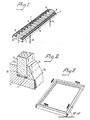
- So that the invention will be more readily understood and further features thereby made apparent, an exemplary embodiment of the invention will now be described with reference to the accompanying schematic drawings, in which
- Fig 1 is a perspective view of a supporting and bracing element according to the present invention,
- Fig 2 illustrates an element mounted in a glazed frame bar and
- Fig 3 illustrates the mounting of elements in a frame bar which inclines 15-45° and is intended to be used for a special hang.
- In Fig 1 the supporting and
bracing element 1 comprises two elongatedparallel edge ribs ribs part 5. the thickness of thecentral part 5 of the transverse ribs 4 is less than the thickness of theedge ribs central part 5 have an arched tapering thickness in a direction towards its central portion. A loop orbridge formation 8 is provided at theend 7 of theedge ribs formation 8 is connecting theedge ribs edge ribs bridge formation 8 has an extension perpendicular to the upper side of the supporting and bracing element whiich mainly corresponds to the thickness of theedge ribs element 1 between theedge portion 10 of a sealed glazing unit 9 and a surroundingframe bar 11 the loop orbridge formation 8 is compressible to the same thickness as theedge ribs loop formation 8 outside theshort side 12 of theedge ribs bridge formation 8 is fastened to theends 7 of theedge ribs - A
grooving 13 is provided on the upper- and under side of theedge ribs elements 1 placed one on top of each other and in the same time prevent a sliding movement laterally of theelements 1 in relation to each other. Twolocking pins 14 are provided on one longitudinal side of theedge ribs edge ribs bridge formation 8. Thelocking pins 14 are provided to fix the supporting and bracingelement 1 after mounting of aglazing bar 15. The supporting andbracing elements 1 are preferably manufactured of plastics material in different thicknesses of theedge ribs elements 1 one on top of each other cover the actual distances which exist between theedge portion 10 of a sealed glazing unit 9 and a surroundingframe bar 11. In order to distinguishelements 1 having different thickness easier from each other a special colour can be used for each thickness.
Claims (7)
Priority Applications (1)
| Application Number | Priority Date | Filing Date | Title |
|---|---|---|---|
| AT82902273T ATE23207T1 (en) | 1982-07-30 | 1982-07-30 | SUPPORT AND ANCHORING ELEMENTS FOR LAMINATED GLASS UNITS. |
Applications Claiming Priority (1)
| Application Number | Priority Date | Filing Date | Title |
|---|---|---|---|
| PCT/SE1982/000253 WO1984000574A1 (en) | 1982-07-30 | 1982-07-30 | Elements for supporting and bracing sealed-glazing units |
Publications (2)
| Publication Number | Publication Date |
|---|---|
| EP0129539A1 EP0129539A1 (en) | 1985-01-02 |
| EP0129539B1 true EP0129539B1 (en) | 1986-10-29 |
Family
ID=20345755
Family Applications (1)
| Application Number | Title | Priority Date | Filing Date |
|---|---|---|---|
| EP82902273A Expired EP0129539B1 (en) | 1982-07-30 | 1982-07-30 | Elements for supporting and bracing sealed-glazing units |
Country Status (5)
| Country | Link |
|---|---|
| US (1) | US4512125A (en) |
| EP (1) | EP0129539B1 (en) |
| AT (1) | ATE23207T1 (en) |
| DE (1) | DE3274004D1 (en) |
| WO (1) | WO1984000574A1 (en) |
Families Citing this family (11)
| Publication number | Priority date | Publication date | Assignee | Title |
|---|---|---|---|---|
| FR2585401A1 (en) * | 1985-07-23 | 1987-01-30 | Arban | DEVICE FOR SETTING INSULATING GLAZING ON EXTERNAL JOINERY |
| DE9108808U1 (en) * | 1991-07-17 | 1991-09-12 | Niemann, Hans Dieter, 5014 Kerpen | Support part for glass panes of windows, doors, etc. |
| USD348596S (en) | 1992-11-06 | 1994-07-12 | Slaydon Mason E | Transom support |
| DE4239735A1 (en) * | 1992-11-26 | 1994-06-01 | Hans Dieter Niemann | Support part for glass panes of windows, doors or the like. |
| US5822934A (en) * | 1997-04-15 | 1998-10-20 | O'donnell; Richard | Drain |
| US6374557B1 (en) | 2000-06-30 | 2002-04-23 | Ashland Products, Inc. | Weep hole construction |
| US8534020B2 (en) * | 2011-08-22 | 2013-09-17 | Taylor Craft Cabinet Door L.P. | Cabinet door panel lock |
| EP2837766A1 (en) * | 2013-08-14 | 2015-02-18 | Sika Technology AG | Method for filling a joint with an adhesive and/or sealant, and system for filling a joint with an adhesive and/or sealant |
| US9790731B1 (en) * | 2014-12-19 | 2017-10-17 | Andersen Corporation | Fenestration units with spacer blocks and methods of manufacturing the same |
| US11933098B1 (en) * | 2023-03-20 | 2024-03-19 | Pella Corporation | Fenestration unit with interior installation features and associated systems and methods |
| US12180777B2 (en) | 2023-05-01 | 2024-12-31 | Pella Corporation | Fenestration unit installation clips and associated methods |
Family Cites Families (4)
| Publication number | Priority date | Publication date | Assignee | Title |
|---|---|---|---|---|
| SE401385B (en) * | 1977-01-21 | 1978-05-02 | Eriksson Lars | DISTANCE ELEMENT FOR INSULATION RUTOR |
| SE408205B (en) * | 1977-09-29 | 1979-05-21 | Eriksson Lars | DEVICE FOR DISTANCE ELEMENT |
| SE418884B (en) * | 1978-03-10 | 1981-06-29 | Lennart Tibratt | DISTANCE CLASS AT WINDOWS |
| IT1136411B (en) * | 1980-06-17 | 1986-08-27 | Oddo Borghetto | COMPLEX OF SPACER ELEMENTS AND ALIGNERS FOR BLOCKS PARTICULARLY SUITABLE FOR WALLS OR CONCRETE GLASS PANELS |
-
1982
- 1982-07-30 US US06/598,317 patent/US4512125A/en not_active Expired - Fee Related
- 1982-07-30 WO PCT/SE1982/000253 patent/WO1984000574A1/en not_active Ceased
- 1982-07-30 AT AT82902273T patent/ATE23207T1/en not_active IP Right Cessation
- 1982-07-30 EP EP82902273A patent/EP0129539B1/en not_active Expired
- 1982-07-30 DE DE8282902273T patent/DE3274004D1/en not_active Expired
Also Published As
| Publication number | Publication date |
|---|---|
| ATE23207T1 (en) | 1986-11-15 |
| US4512125A (en) | 1985-04-23 |
| EP0129539A1 (en) | 1985-01-02 |
| WO1984000574A1 (en) | 1984-02-16 |
| DE3274004D1 (en) | 1986-12-04 |
Similar Documents
| Publication | Publication Date | Title |
|---|---|---|
| GB2081790A (en) | Cladding for window frames | |
| US4015388A (en) | Retaining clip for a division bar | |
| US4512125A (en) | Elements for supporting and bracing sealed-glazing units | |
| DE3773297D1 (en) | RAIN PROTECTION RAIL FOR WINDOWS. | |
| AT383861B (en) | CORNER ANGLE FOR INSERTION IN HOLLOW PROFILE BARS FOR FRAME FOR WINDOWS, DOORS, FACADE ELEMENTS OR THE LIKE. | |
| CA1098377A (en) | Elements for supporting and bracing sealed-glazing units | |
| IT8421613U1 (en) | JOINT WITH SQUARE INSERT FOR CONNECTING DOUBLE GLAZING FRAME PROFILES. | |
| ATE20375T1 (en) | BLOCK BRIDGE FOR SECURING GLASS PANES OD. DGL. IN DOOR OR WINDOW FRAMES. | |
| ATA238287A (en) | GLAZING PROFILE FOR DOORS, WINDOWS OR THE LIKE. | |
| DK306685A (en) | DEVICE FOR SECURING OR LOCKING A HANGED FLAT LIKE A WINDOW | |
| US4194334A (en) | Self-sealing solar collector shield | |
| FR2562598B1 (en) | HARDWARE FOR A WINDOW, A DOOR OR THE LIKE | |
| IT210055Z2 (en) | SLVEOLAR PANEL FOR WINDOWS OR SKYLIGHTS. | |
| CA1255156A (en) | Elements for supporting and bracing sealed-glazing units | |
| GB2180871B (en) | Window support and condensation drainage element | |
| DE2805258A1 (en) | Window or glazed door bar cover plate retainer - involves locking unit engaging grooves in plate bend and adjacent side surface | |
| FR2622625B1 (en) | WINDOW, DOOR OR THE LIKE HAVING A MOVABLE WING | |
| AT371201B (en) | LOCKING DEVICE FOR WING OF WINDOWS, DOORS OR THE LIKE. IN AT LEAST ONE CLEAN VENTILATION POSITION | |
| IT210034Z2 (en) | RUBBER GASKET BETWEEN THE GLASS SHEET AND THE GLASS HOLDING FRAME OF A SECTION FOR WINDOWS. | |
| ATA234885A (en) | LOCKING PLATE FOR WINDOW AND DOOR LATCHES OR THE LIKE. | |
| DK0659228T3 (en) | A window, door or the like and especially a sliding bracket for the same | |
| DE2855340A1 (en) | Pane retention on rail - involves clamp pieces fastened to inside of bar which covers them | |
| ATA68180A (en) | FASTENING ELEMENT FOR A FENCE, DOOR OR WINDOW GRILL | |
| ATA454782A (en) | SIDE FITTING FOR TURN-TIP WINDOWS, DOORS OR THE LIKE. | |
| GB2233019A (en) | A device for securing a glass sheet in a frame |
Legal Events
| Date | Code | Title | Description |
|---|---|---|---|
| PUAI | Public reference made under article 153(3) epc to a published international application that has entered the european phase |
Free format text: ORIGINAL CODE: 0009012 |
|
| 17P | Request for examination filed |
Effective date: 19840822 |
|
| AK | Designated contracting states |
Kind code of ref document: A1 Designated state(s): AT BE CH DE FR GB LI NL |
|
| GRAA | (expected) grant |
Free format text: ORIGINAL CODE: 0009210 |
|
| AK | Designated contracting states |
Kind code of ref document: B1 Designated state(s): AT BE CH DE FR GB LI NL |
|
| PG25 | Lapsed in a contracting state [announced via postgrant information from national office to epo] |
Ref country code: NL Effective date: 19861029 Ref country code: LI Effective date: 19861029 Ref country code: FR Free format text: THE PATENT HAS BEEN ANNULLED BY A DECISION OF A NATIONAL AUTHORITY Effective date: 19861029 Ref country code: CH Effective date: 19861029 Ref country code: BE Effective date: 19861029 Ref country code: AT Effective date: 19861029 |
|
| REF | Corresponds to: |
Ref document number: 23207 Country of ref document: AT Date of ref document: 19861115 Kind code of ref document: T |
|
| REF | Corresponds to: |
Ref document number: 3274004 Country of ref document: DE Date of ref document: 19861204 |
|
| REG | Reference to a national code |
Ref country code: CH Ref legal event code: PL |
|
| EN | Fr: translation not filed | ||
| NLV1 | Nl: lapsed or annulled due to failure to fulfill the requirements of art. 29p and 29m of the patents act | ||
| PLBE | No opposition filed within time limit |
Free format text: ORIGINAL CODE: 0009261 |
|
| STAA | Information on the status of an ep patent application or granted ep patent |
Free format text: STATUS: NO OPPOSITION FILED WITHIN TIME LIMIT |
|
| 26N | No opposition filed | ||
| PGFP | Annual fee paid to national office [announced via postgrant information from national office to epo] |
Ref country code: GB Payment date: 19910730 Year of fee payment: 10 |
|
| PG25 | Lapsed in a contracting state [announced via postgrant information from national office to epo] |
Ref country code: GB Effective date: 19920730 |
|
| GBPC | Gb: european patent ceased through non-payment of renewal fee |
Effective date: 19920730 |
|
| PGFP | Annual fee paid to national office [announced via postgrant information from national office to epo] |
Ref country code: DE Payment date: 20000803 Year of fee payment: 19 |
|
| PG25 | Lapsed in a contracting state [announced via postgrant information from national office to epo] |
Ref country code: DE Free format text: LAPSE BECAUSE OF NON-PAYMENT OF DUE FEES Effective date: 20020501 |