EP0129165B1 - Ink dot printer - Google Patents
Ink dot printer Download PDFInfo
- Publication number
- EP0129165B1 EP0129165B1 EP84106581A EP84106581A EP0129165B1 EP 0129165 B1 EP0129165 B1 EP 0129165B1 EP 84106581 A EP84106581 A EP 84106581A EP 84106581 A EP84106581 A EP 84106581A EP 0129165 B1 EP0129165 B1 EP 0129165B1
- Authority
- EP
- European Patent Office
- Prior art keywords
- electromagnet
- magnetic
- magnetic force
- ink
- dot printer
- Prior art date
- Legal status (The legal status is an assumption and is not a legal conclusion. Google has not performed a legal analysis and makes no representation as to the accuracy of the status listed.)
- Expired
Links
- 230000005389 magnetism Effects 0.000 claims description 19
- 239000003990 capacitor Substances 0.000 claims description 6
- 238000000034 method Methods 0.000 description 8
- 230000003287 optical effect Effects 0.000 description 7
- 230000008569 process Effects 0.000 description 7
- 238000009423 ventilation Methods 0.000 description 3
- 230000009471 action Effects 0.000 description 2
- 238000007796 conventional method Methods 0.000 description 2
- 230000007423 decrease Effects 0.000 description 2
- 230000003247 decreasing effect Effects 0.000 description 2
- 239000000428 dust Substances 0.000 description 2
- 230000008020 evaporation Effects 0.000 description 2
- 238000001704 evaporation Methods 0.000 description 2
- 238000004519 manufacturing process Methods 0.000 description 2
- 238000006424 Flood reaction Methods 0.000 description 1
- 230000008859 change Effects 0.000 description 1
- 238000010276 construction Methods 0.000 description 1
- 238000010586 diagram Methods 0.000 description 1
- 230000004907 flux Effects 0.000 description 1
- 230000006870 function Effects 0.000 description 1
- 230000005415 magnetization Effects 0.000 description 1
- 238000005259 measurement Methods 0.000 description 1
- 238000012986 modification Methods 0.000 description 1
- 230000004048 modification Effects 0.000 description 1
- 230000000717 retained effect Effects 0.000 description 1
- 229920006395 saturated elastomer Polymers 0.000 description 1
- 238000012546 transfer Methods 0.000 description 1
Images



Classifications
-
- B—PERFORMING OPERATIONS; TRANSPORTING
- B41—PRINTING; LINING MACHINES; TYPEWRITERS; STAMPS
- B41J—TYPEWRITERS; SELECTIVE PRINTING MECHANISMS, i.e. MECHANISMS PRINTING OTHERWISE THAN FROM A FORME; CORRECTION OF TYPOGRAPHICAL ERRORS
- B41J2/00—Typewriters or selective printing mechanisms characterised by the printing or marking process for which they are designed
- B41J2/22—Typewriters or selective printing mechanisms characterised by the printing or marking process for which they are designed characterised by selective application of impact or pressure on a printing material or impression-transfer material
- B41J2/23—Typewriters or selective printing mechanisms characterised by the printing or marking process for which they are designed characterised by selective application of impact or pressure on a printing material or impression-transfer material using print wires
- B41J2/235—Print head assemblies
- B41J2/25—Print wires
- B41J2/255—Arrangement of the print ends of the wires
-
- B—PERFORMING OPERATIONS; TRANSPORTING
- B41—PRINTING; LINING MACHINES; TYPEWRITERS; STAMPS
- B41J—TYPEWRITERS; SELECTIVE PRINTING MECHANISMS, i.e. MECHANISMS PRINTING OTHERWISE THAN FROM A FORME; CORRECTION OF TYPOGRAPHICAL ERRORS
- B41J2/00—Typewriters or selective printing mechanisms characterised by the printing or marking process for which they are designed
- B41J2/22—Typewriters or selective printing mechanisms characterised by the printing or marking process for which they are designed characterised by selective application of impact or pressure on a printing material or impression-transfer material
- B41J2/23—Typewriters or selective printing mechanisms characterised by the printing or marking process for which they are designed characterised by selective application of impact or pressure on a printing material or impression-transfer material using print wires
- B41J2/305—Ink supply apparatus
Definitions
- the present invention relates to an ink dot printer comprising; a means for storing magnetic ink; a pair of magnetic pole plates arranged opposite to each other to form a slit whose one end is immersed in magnetic ink supplied from the magnetic ink storing means; a magnetism generating means for magnetizing the pair of magnetic pole plates to introduce magnetic ink supplied from the magnetic ink storing means into the slit and form a magnetic ink film in the slit; a plurality of needles arranged adjacent to one another along the longitudinal direction of the slit and each freely movable in the longitudinal direction of the needle between a first position where its one end portion is immersed in the magnetic ink film in the slit formed by the paired magnetic pole plates and a second position where its one end portion is projected from the magnetic ink film in the slit; and a driving means for selectively driving the needles to move from the first position to the second position, wherein the one or more needles selected force magnetic ink, which has been stuck on their end faces of the
- the wire dot printer or thermal printer is normally used as the ink dot printer.
- the wire dot printer selectively drives needles whose tips directly strike a pressure-sensitive manifold paper on a platen or whose tips indirectly strike a recording paper on the platen through an ink ribbon interposed between the tips of the needles and the recording paper.
- dots are formed on the pressure-sensitive manifold paper or recording paper to print symbols, such as characters or numerals, by the grouping of these dots.
- a large amount of noise is caused when the symbols are printed onto the pressure-sensitive manifold paper or recording paper.
- no other paper except for the pressure-sensitive manifold paper can be used.
- the expensive ink ribbon of the latter method must be changed frequently.
- the expensive ink ribbon also must be used in the thermal printer.
- the density of dots formed on the recording paper is uniform, thereby keeping densities of printed symbols, such as characters and numerals, uniform.
- .It is also known an ink-dot-printer (EP-A-0121 242 falling within the terms of Art. 54(3) EPC), in which the cross-sectional area of the one end portion of each one of a plurality of needles is made to narrower than that of the remaining portion of the needle so that the distance between the one end portions of any two adjacent needles is widened to prevent magnetic ink from being retained between the portions adjacent to the end faces of the one end portions by surface tension when the two needles are simultaneously projected from a magnetic ink curtain formed in the slit of a pair of magnetic pole plates.
- the present invention is intended to eliminate the above-mentioned drawbacks, and the object of the present invention is, therefore, to provide an ink dot printer capable of freely determining the density of dots and, therefore, also the densities of printed symbols, such as characters and numerals, without generating a loud noise at the time of forming the dots on a recording paper.
- an ink dot printer comprising a means for storing magnetic ink; a pair of magnetic pole plates arranged opposite to each other to form a slit, whose one end is immersed in the magnetic ink supplied from the magnetic ink storing means; a magnetism generating means for magnetizing the paired magnetic pole plates to introduce the magnetic ink supplied from the magnetic ink storing means into the slit to form a magnetic ink film therein; a plurality of needles arranged adjacent to one another along the longitudinal direction of the slit and each freely movable in the longitudinal direction of the needle between a first.position where its one-end portion is immersed in the magnetic ink film in the slit between the paired magnetic pole plates and a second position where its one end portion is projected from the magnetic ink film in the slit; and a driving means for selectively driving the needles to move them from the first to the second position; wherein the single or plural needles selected force the magnetic ink, which has been stuck to their
- the magnetism generating means has an electromagnet, and that the magnetic force control means controls current or voltage supplied to the electromagnet to control the strength of magnetic force generated by the electromagnet.
- the construction of the magnetic force control means is simple, thereby allowing the manufacturing and assembly of the magnetic force control means to be simplified.
- the magnetic force control means can have a variable resistance which controls the strength of magnetic force generated by the electromagnet by controlling voltage supplied to the electromagnet.
- the magnetic force control means can have an automatic print density holding means which reads the density of dots on the recording paper, compares it with the reference density previously set, and controls the current or voltage supplied to the electromagnet on the basis of a value obtained by comparing the densities, thereby to control the strength of magnetic force generated by the electromagnet and hold the density of dots formed on the recording paper equal to the reference density.
- the automatic print density holding means can have a variable resistance which controls the strength of magnetic force generated by the electromagnet by controlling voltage supplied to the electromagnet.
- the density of the dots formed can be held equal to the reference density previously set with relative exactness for a relatively long time period.
- the automatic print density holding means which can achieve such a function can be very easily prepared by those skilled in the art by combining the conventional techniques.
- a through-hole is normally provided in the magnetic ink storing means to supply the magnetic ink from the magnetic ink storing means into the slit between the paired magnetic pole plates. And it is desired that the cross-sectional area of this through-hole is made as small as possible to prevent the evaporation of magnetic ink in the magnetic ink storing means and to prevent dust from entering into the magnetic ink storing means.
- the cross-sectional area of the through-hole is made too small, however, the magnetic ink floods out of the through-hole and splashes around the magnetic ink storing means. This happens the magnetization of the paired magnetic pole plates, by means of the magnetism generating means, is stopped to collect the magnetic ink from the slit through the through-hole into the magnetic means at the time of finishing the printing operation of the ink dot printer.
- the magnetic force control means has a magnetic force gradually lowering means for gradually reducing the strength of the magnetic force at the time when the magnetic generating means finishes its magnetic force generating operation in order to prevent the magnetic ink from splashing out of the through-hole even when the cross-sectional area of the through-hole is small.
- the strength of magnetic force generated in the slit is gradually decreased, and the magnetic ink in the slit is not concentrated but gradually advanced to the magnetic ink storing means, thereby preventing the magnetic ink from flooding out of the through-hole.
- the magnetism generating means has the electromagnet and the magnetic force lowering means can be a capacitor electrically connected to the electromagnet.
- This magnetic force lowering means having such an arrangement can be easily constructed, and the manufacturing and assembly thereof can be simplified.
- FIG. 1 An ink dot printer of the first embodiment of the present invention is roughly shown in Fig. 1.
- a platen 12 is horizontally arranged with its longitudinally central axis extending in a right and left direction, and a carrier shaft 14 and a guide shaft 16 are arranged in parallel to the longitudinally central axis of the platen 12.
- a carriage 18 is mounted so as to be reciprocate along the carrier shaft 14 and the guide shaft 16.
- the carriage 18 is reciprocatably driven by the well known carriage driving means.
- a printing head 20 and an ink film forming means 22 are mounted on the carriage 18.
- the housing 10 has a cover 24 which covers the platen 12, carrier shaft 14, guide shaft 16, carriage 18, printing head 20, and ink film forming means 22, as shown in Fig. 1.
- the cover 24 is partially cut off in Fig. 1 for clarity of description.
- the ink film forming means 22 has an electromagnet 26 whose opposite ends are attached to a pair of magnetic pole plates 28 and 30.
- the front end portions 32 and 34 of the paired magnetic pole plates 28 and 30 are adapted to form a slit 36, under which is arranged an ink tank 38 as a magnetic ink storing means which is freely detachable from the carriage 18.
- a slot 40 into which the lower ends of the front end portions 32 and 34 of the paired magnetic pole plates 28 and 30 are inserted is formed in the upper face of the ink tank 38, said slot 40 having in the center thereof a ventilation hole 42 which corresponds to the slit 36 of the paired magnetic pole plates 28 and 30.
- a hole 46 for connecting an ink cartridge 44 therewith is also formed in the upper face of the ink tank 38.
- a sleeve 48 detachably fitted into the connecting hole 46 of the ink tank 38, is formed on the underside of the ink cartridge 44.
- a spring 50 and a plate-shaped plug 52 which is urged downward by the spring 50 are arranged in the sleeve 48.
- the plug 52 has a push rod 56 extending downward to project outside through a discharge opening 54 which is formed in the bottom of the sleeve 48.
- the plug 52 is also provided with plural cut-away portions 58 on the outer circumference thereof. The radius of a circle which connects the inner ends of these cut-away portions 58 is set to be larger than that of the discharge opening 54.
- the push rod 56 is brought into contact with the inner face of the bottom of the ink tank 38 to separate the plug 52 from the discharge opening 54 against the action of the spring 50, as shown in Fig. 4, when the sleeve 48 is fitted into the connecting hole 46 of the ink tank 38. Accordingly, magnetic ink 60 in the ink cartridge 44 flows into the ink tank 38 through the cut-away portions 58 of the plug 52 and the discharge opening 54 of the sleeve 48.
- the flow of magnetic ink 60 into the ink tank 38 stops when the level of magnetic ink 60 in the ink tank 38 reaches the discharge opening 54 of the sleeve 48 of the ink cartridge 44, and thereafter, the level of magnetic ink 60 in the ink tank 38 is kept equal to the level of the discharge opening 54 of the sleeve 48 of the ink cartridge 44 until no magnetic ink 60 is left in the ink cartridge 44.
- the front end portions 32 and 34 of the paired magnetic pole plates 28 and 30, which have been inserted into the slot 40 of the ink tank 38, are immersed in the magnetic ink 60 in the ink tank 38 at this time, as shown in Fig. 4.
- one end portions of the needles 62 can be found in the slit 36 of the paired magnetic pole plates 28 and 30.
- the other end portions of the same needles 62 extend through a frame 64 arranged between the paired magnetic pole plates 28 and 30, as shown in Figs. 2 and 3, and into the cover 66 of the printing head 20, as shown in Fig. 5.
- the needles 62 are held in place by needle guides 68 and 70, which permit the needles 62 to be freely movable in the longitudinal direction.
- the position of the needles 62 in this state is represented as the first position of the needles 62.
- electromagnets 72 which serve as a means for driving the needles 62 are arranged in the cover 66 of the printing head 20 to correspond to the plural needles 62.
- Armatures 74 connected to the other end portions of the needles 62, are arranged adjacent to the electromagnets 72.
- the needles 62 are urged together with the armatures 74 toward their first position shown in Fig. 5 by the action of the return springs 76, each of which is fitted onto an individual needle 62.
- the armatures, in this state, 74 are contacted with a contact member 78.
- a recording paper 82 which is fed by paper feed rollers 80 is arranged in front of the printing head 20 and ink film forming means 22 inside the housing 10 shown in Fig. 1.
- the recording paper 82 is also rested on the platen 12, corresponding to the needles 62.
- the platen 12 is made of a magnet in this embodiment.
- a capacitor 84 is electrically connected between both poles of the electromagnet 26, which serves as the magnetism generating means for magnetizing the paired pole plates 28 and 30, as shown in Fig. 6.
- a variable resistance 88 and a main switch 90 are electrically connected between the electromagnet 26 and a power source 86 for the electromagnet 26, respectively. These variable resistance 88 and main switch 90 can be operated by knobs 92 and 94, respectively, which are arranged on the housing 10 of the ink dot printer of the embodiment shown in Fig. 1.
- the magnetic ink 60 in the ink tank 38 is drawn into the slit 36 between the paired magnetic pole plates 28 and 30 thanks to the magnetic flux created between the paired magnetic pole plates 28 and 30, and a film 96 of magnetic ink is formed in the slit 36, as shown in Fig. 7.
- the magnetic ink film 96 in the slit 36 immerses the one end portions of the needles 62 located at the first position.
- the magnetic ink 60 stuck on the end face of one end portion of the needle 62, located at the second position as shown in Fig. 9, is drawn to the recording paper 82 on the platen 12 due to inertial force caused in the magnetic ink 60 at the moment when the needle 62 is stopped at the second position and also due to magnetic force created by the platen 12, which is made of magnet, thereby forming a dot of the magnetic ink 60 on the recording paper 82 on the platen 12, as shown in Fig. 10.
- the magnetic ink 60 on the end face of one end portion of the needle 62 is lightly contacted with the recording paper 82 on the platen 12 when the needle 62 is located at the second position, and transferred onto the recording paper 82 to form a dot on the recording paper 82 with the transferred magnetic ink 60.
- Fig. 11 shows the relation between the current voltage, that is exciting voltage, supplied to the electromagnet 26, which serves as the magnetism generating means, and the strength of the magnetic field, generated in the slit 36 between the paired magnetic pole plates, from which it can be found that the strength of the magnetic field becomes saturated when the exciting voltage becomes larger than a certain value.
- the strength of the exciting voltage supplied to the electromagnet 26 is adjusted by operating the variable resistance 88, in Fig. 6, through the knob 92 on the housing 10, in that area where the exciting voltage can change the strength of magnetic field linearly the strength of magnetic field generated in the slit 36 changes, thereby enabling the thickness (D) of the magnetic ink film 96 in the slit 36 to be varied linearly.
- the thickness (D) represents the dimensions of the magnetic ink film 96 measured in a direction along the longitudinal center line of the needle 62, as shown in Fig. 7. As this dimension (D) increases, the amount of the magnetic ink 60 stuck on the end face of one end portion of the needle 62 increases, and the density of the dot formed on the recording paper 82 with the magnetic ink 60, transferred from the end face of the needle 62 onto the recording paper 82 on the platen 12, thus increases. When the dimension (D) is decreased, however, the amount of the magnetic ink 60 stuck on the end face of one end portion of the needle 62 decreases and the density of the dot formed on the recording paper 82 thus becomes thinner.
- the magnetic ink 60 which forms the magnetic ink film 96 in the slit 36 between the paired magnetic pole plates 28 and 30 does not rush toward the ink tank 38 through the ventilation hole 42 thereof at the moment when the main switch is turned OFF, but is gradually collected into the ink tank 38 through the ventilation hole 42 thereof, following the gradual vanishing of magnetic field in the slit 36.
- the magnetic ink 60 will not flood out of the hole 42 of the ink tank 38 and spread around the ink tank 38 at the time of collecting the magnetic ink 60 into the ink tank 38.
- the electromagnet 26 which serves as the magnetism generating means for exiting the paired magnetic pole plates 28 and 30 is combined with an automatic print density maintaining means, which reads the density of dots on the recording paper 82, compares it with the reference density previously set, and controls current or voltage supplied to the electromagnet 26 on the basis of a value obtained by comparing the densities, thereby to control the strength of magnetic force generated by the electromagnet 26 and maintain the density of the dots formed on the recording paper equal to the reference density.
- the automatic print density maintaining means 98 can use the variable resistance 88 in Fig. 6 to control the strength of magnetic force generated by the electromagnet 26.
- This automatic print density maintaining means 98 can be very easily made by those who are skilled in the art by combining the conventional techniques.
- Fig. 13 shows an example of the flow chart for the automatic print density maintaining means 98.
- the ink dot printer provided with the automatic print density maintaining means 98 has an optical print density detecting means 100, which is located left side of the needles 62 of the printing head 20 in Fig. 2 and fixed to the carriage 18, for example.
- This optical print density detecting means 100 can measure the density of dots of the magnetic ink 60 formed on the recording paper 82 on the platen 12 by the needles 62 of the printing head 20 when the carriage 18 is moving from left to right in Figs. 1 and 2.
- the ink dot printer In the case of the ink dot printer, at first, dots of the magnetic ink 60 are formed on the recording paper 82 on the platen 12 by the needles 62 of the printing head 20 when the carriage 18 is moving from left to right or from right to left in Figs. 1 and 2. At the next time, the recording paper 82 is fed by one line by the feeding rollers 80 in the second step 104, and whether, for example, the 60-line printing is finished or not is checked in the third step 106. When the 60-line printing is not finished, the first step 102 also causes the printing head 20, in contrast to the printing in the before line, to print from right to left or from left to right.
- the automatic print density maintaining means 98 first causes the printing head 20 to print, for example, sixty lines on the recording paper 82. After confirming that the 60-line printing is finished, according to a fourth step 108, it is confirmed that the carriage 18 is located at the left side of the carrier shaft 14 and the guide shaft 16, as shown in Figs. 1 and 2. When the carriage 18 is located at the left side, a further line is printed on the recording paper 82 according to a fifth step 110, causing the carriage 18 to move from left to right in Figs. 1 and 2.
- a sixth step 111 causes the carriage 18 to print from right to left, and the recording paper 82 is fed by one line by the feeding rollers 80 in a seventh step 112, and then printing of a further line from left to right is achieved, as described above according to the fifth step 110.
- This digitalized density of the symbol measured is compared with the reference density of printed words according to a tenth step 118.
- the measured symbol such as a character or numeral, being lastly printed in the printing process at the fifth step 110, and said reference density of printed words being previously stored in a memory circuit and read out according to a ninth step 116.
- a twelfth step 122 is selected by an eleventh step 120, and the variable resistance 88 is controlled by a step motor, for example, at the twelfth step 122 to increase its resistance value.
- the step motor causes the variable resistance 88 to have a resistance value by which the thickness (D) of the magnetic ink film 96 can be made to correspond to a digital Value of the measured density from which only one is subtracted.
- This resistance value setting process at the twelfth step 122 is repeated until the variable resistance 88 comes to have such a resistance value that allows the magnetic ink film 96 to have a thickness (D) which makes the measured density coincided with the reference density.
- a fourteenth step 126 causes the feeding rollers 80 to feed the recording paper 82 by one line to prepare the printing of a next line. When the fourteenth step 126 is finished, printing can be done on a new sheet of recording paper with dots which have same density as those dots used to print the previous sheets of recording paper.
- the fifteenth step 128 is selected by the eleventh step 120, and it is judged at the fifteenth step 128 whether or not the measured density coincides with the reference density. When the coincidence of these densities is confirmed, the fourteenth step 126 is selected to prepare the printing process on a next sheet of recording paper.
- a sixteenth step 130 is selected since the measured density is lower than the reference density, and the variable resistance is controlled by the step motor, for example, at the sixteenth step 130 to decrease its resistance value.
- the step motor causes the variable resistance 88 to have resistance value by which the thickness (D) of the magnetic ink film 96 can be made to correspond to a digital value of the measured density to which only one is added.
- This resistance value setting process at the sixteenth step 130 is repeated until the variable resistance 88 comes to have such a resistance value, according to a seventeenth step 132, that it allows the magnetic ink film 96 to have a thickness (D) which makes the measured density coincided with the reference density.
- the fourteenth step 126 is selected to prepare the printing process on the next sheet of recording paper.
- the measurement and digitalization of the density of printed symbols by means of the optical print density detecting means 100 is not limited to the time of printing a sixty-first line, but may be done at the time when an optical line is printed or every time when a character, not a line, is printed.
- the automatic print density maintaining means 98 can be operated, using a flow chart substantially the same as that of Fig. 13, even in the case where the dots of magnetic ink 60 are formed on the recording paper 82 on the platen 12 by the needles 62 of the printing head 20 when the carriage 18 is moving from right to left in Figs. 1 and 2.
- the density of symbols printed by the automatic print density maintaining means 98 may be changed.
Landscapes
- Impact Printers (AREA)
Description
- The present invention relates to an ink dot printer comprising; a means for storing magnetic ink; a pair of magnetic pole plates arranged opposite to each other to form a slit whose one end is immersed in magnetic ink supplied from the magnetic ink storing means; a magnetism generating means for magnetizing the pair of magnetic pole plates to introduce magnetic ink supplied from the magnetic ink storing means into the slit and form a magnetic ink film in the slit; a plurality of needles arranged adjacent to one another along the longitudinal direction of the slit and each freely movable in the longitudinal direction of the needle between a first position where its one end portion is immersed in the magnetic ink film in the slit formed by the paired magnetic pole plates and a second position where its one end portion is projected from the magnetic ink film in the slit; and a driving means for selectively driving the needles to move from the first position to the second position, wherein the one or more needles selected force magnetic ink, which has been stuck on their end faces of the one end portions at the first position, onto a recording paper at the second position to form dots of magnetic ink on the recording paper so as to print symbols such as characters or numerals on the recording paper by the grouping of these dots.
- The wire dot printer or thermal printer is normally used as the ink dot printer. The wire dot printer selectively drives needles whose tips directly strike a pressure-sensitive manifold paper on a platen or whose tips indirectly strike a recording paper on the platen through an ink ribbon interposed between the tips of the needles and the recording paper. In this fashion, dots are formed on the pressure-sensitive manifold paper or recording paper to print symbols, such as characters or numerals, by the grouping of these dots. In this conventional wire dot printer, however, a large amount of noise is caused when the symbols are printed onto the pressure-sensitive manifold paper or recording paper. In addition, no other paper except for the pressure-sensitive manifold paper can be used. Further, the expensive ink ribbon of the latter method must be changed frequently. The expensive ink ribbon also must be used in the thermal printer.
- In order to eliminate the drawbacks of the conventional wire dot printer or thermal printer, there have been proposed various kinds of ink dot printers wherein magnetic ink is stuck on the end faces of the front end portions of the needles and wherein these needles are driven selectively to transfer the magnetic ink onto the recording paper to form dots thereon.
- In the case of the conventional wire dot and thermal printers as described above, the density of dots formed on the recording paper is uniform, thereby keeping densities of printed symbols, such as characters and numerals, uniform.
- .It is also known an ink-dot-printer (EP-A-0121 242 falling within the terms of Art. 54(3) EPC), in which the cross-sectional area of the one end portion of each one of a plurality of needles is made to narrower than that of the remaining portion of the needle so that the distance between the one end portions of any two adjacent needles is widened to prevent magnetic ink from being retained between the portions adjacent to the end faces of the one end portions by surface tension when the two needles are simultaneously projected from a magnetic ink curtain formed in the slit of a pair of magnetic pole plates.
- The present invention is intended to eliminate the above-mentioned drawbacks, and the object of the present invention is, therefore, to provide an ink dot printer capable of freely determining the density of dots and, therefore, also the densities of printed symbols, such as characters and numerals, without generating a loud noise at the time of forming the dots on a recording paper.
- The object of the present invention can be achieved by an ink dot printer comprising a means for storing magnetic ink; a pair of magnetic pole plates arranged opposite to each other to form a slit, whose one end is immersed in the magnetic ink supplied from the magnetic ink storing means; a magnetism generating means for magnetizing the paired magnetic pole plates to introduce the magnetic ink supplied from the magnetic ink storing means into the slit to form a magnetic ink film therein; a plurality of needles arranged adjacent to one another along the longitudinal direction of the slit and each freely movable in the longitudinal direction of the needle between a first.position where its one-end portion is immersed in the magnetic ink film in the slit between the paired magnetic pole plates and a second position where its one end portion is projected from the magnetic ink film in the slit; and a driving means for selectively driving the needles to move them from the first to the second position; wherein the single or plural needles selected force the magnetic ink, which has been stuck to their one ends at the first position, onto a recording paper at the second position to form dots of magnetic ink, by the gathering of which symbols, such as characters and numerals, are printed, the magnetism generating means having a magnetic force control means for controlling the strength of magnetic force generated by the magnetism generating means.
- In the case of the ink dot printer according to the present invention, it is preferable that the magnetism generating means has an electromagnet, and that the magnetic force control means controls current or voltage supplied to the electromagnet to control the strength of magnetic force generated by the electromagnet. When arranged like this, the construction of the magnetic force control means is simple, thereby allowing the manufacturing and assembly of the magnetic force control means to be simplified.
- In the case where the ink dot printer of the present invention is arranged as described above, the magnetic force control means can have a variable resistance which controls the strength of magnetic force generated by the electromagnet by controlling voltage supplied to the electromagnet.
- According to the ink dot printer of the present invention, the magnetic force control means can have an automatic print density holding means which reads the density of dots on the recording paper, compares it with the reference density previously set, and controls the current or voltage supplied to the electromagnet on the basis of a value obtained by comparing the densities, thereby to control the strength of magnetic force generated by the electromagnet and hold the density of dots formed on the recording paper equal to the reference density. Further, the automatic print density holding means can have a variable resistance which controls the strength of magnetic force generated by the electromagnet by controlling voltage supplied to the electromagnet.
- When constructed like this, the density of the dots formed can be held equal to the reference density previously set with relative exactness for a relatively long time period. And the automatic print density holding means which can achieve such a function can be very easily prepared by those skilled in the art by combining the conventional techniques.
- With the ink dot printer of the present invention, which uses magnetic ink, a through-hole is normally provided in the magnetic ink storing means to supply the magnetic ink from the magnetic ink storing means into the slit between the paired magnetic pole plates. And it is desired that the cross-sectional area of this through-hole is made as small as possible to prevent the evaporation of magnetic ink in the magnetic ink storing means and to prevent dust from entering into the magnetic ink storing means. When the cross-sectional area of the through-hole is made too small, however, the magnetic ink floods out of the through-hole and splashes around the magnetic ink storing means. This happens the magnetization of the paired magnetic pole plates, by means of the magnetism generating means, is stopped to collect the magnetic ink from the slit through the through-hole into the magnetic means at the time of finishing the printing operation of the ink dot printer.
- According to the ink dot printer of the present invention, the magnetic force control means has a magnetic force gradually lowering means for gradually reducing the strength of the magnetic force at the time when the magnetic generating means finishes its magnetic force generating operation in order to prevent the magnetic ink from splashing out of the through-hole even when the cross-sectional area of the through-hole is small.
- When constructed like this, the strength of magnetic force generated in the slit is gradually decreased, and the magnetic ink in the slit is not concentrated but gradually advanced to the magnetic ink storing means, thereby preventing the magnetic ink from flooding out of the through-hole.
- When the ink dot printer of the present invention is constructed as described above, the magnetism generating means has the electromagnet and the magnetic force lowering means can be a capacitor electrically connected to the electromagnet. This magnetic force lowering means having such an arrangement can be easily constructed, and the manufacturing and assembly thereof can be simplified.
- This invention can be more fully understood from the following detailed description when taken in conjunction with the accompanying drawings, in which:
- Fig. 1 is a perspective view roughly showing the whole of an example of the ink dot printer according to the present invention;
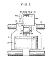
- Fig. 2 is a plane view roughly showing, in enlarged scale, the printing head and ink film forming means in Fig. 1;
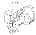
- Fig. 3 is a perspective view roughly showing, in enlarged scale, the whole of the printing head and ink film forming means in Fig. 1, wherein a pair of magnetic pole plates, ink tank and ink cartridge of the ink film forming means are separated from one another for the sake of clarifying the description;
- Fig. 4 is a plane view roughly showing, partly cut off, a part of the ink film forming means in Fig. 1;
- Fig. 5 is a longitudinally sectional view roughly showing the printing head and ink film forming means in Fig. 2, wherein even a platen and a recording paper on the platen are shown, and needles are located at the first position;
- Fig. 6 is a circuit diagram roughly showing connections among a variable resistance, capacitor, power source and main switch, said variable resistance serving as a magnetic force control means for controlling the strength of the magnetic force generated by an electromagnet, which serves as a magnetic force generating means for forming a magnetic field in a slit between the paired magnetic pole plates of an example of the ink dot printer according to the present invention, and said capacitor serving as a magnetic force lowering means for gradually lowering the strength of magnetic force at the time when the magnetic force generating operation of the electromagnet is finished;
- Fig. 7 is a plane view showing, in enlarged scale, the front end portions of the paired magnetic pole plates in Fig. 2 and their adjacent area under such a state that the magnetic ink film is formed in the slit between the front end portions of the paired magnetic pole plates, wherein the needle is located at the first position;
- Fig. 8 is a longitudinally sectional view, similar to Fig. 5, roughly showing a state under which a needle in Fig. 5 is located at the second position;
- Fig. 9 is a plane view showing a state under which the needle in Fig. 7 is located at the second position;
- Fig. 10 is a plane view showing a state under which the needle in Fig. 9 is returned to the first position after having formed a dot of magnetic ink on the recording paper on the platen;
- Fig. 11 shows the relation between voltage of current supplied to the electromagnet, which serves as the magnetism generating means in Figs. 2 and 3, and the strength of magnetic field created in the slit between the paired magnetic pole plates by current having the above voltage;
- Fig. 12 roughly shows the relation between the strength of the magnetic field in Fig. 11 and the thickness (D) of magnetic ink film formed in the slit between the paired magnetic pole plates by the strength of this magnetic field; and
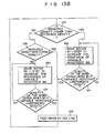
- Figs. 13A and 13B show an example of the flow chart for an automatic print density maintaining means.
- An ink dot printer of the first embodiment of the present invention is roughly shown in Fig. 1. In a
housing 10 of the ink dot printer, aplaten 12 is horizontally arranged with its longitudinally central axis extending in a right and left direction, and acarrier shaft 14 and aguide shaft 16 are arranged in parallel to the longitudinally central axis of theplaten 12. To thecarrier shaft 14 and theguide shaft 16, acarriage 18 is mounted so as to be reciprocate along thecarrier shaft 14 and theguide shaft 16. Thecarriage 18 is reciprocatably driven by the well known carriage driving means. Aprinting head 20 and an ink film forming means 22 are mounted on thecarriage 18. Thehousing 10 has acover 24 which covers theplaten 12,carrier shaft 14,guide shaft 16,carriage 18,printing head 20, and ink film forming means 22, as shown in Fig. 1. Thecover 24 is partially cut off in Fig. 1 for clarity of description. - As shown in Figs. 2 and 3, the ink film forming means 22 has an
electromagnet 26 whose opposite ends are attached to a pair ofmagnetic pole plates front end portions magnetic pole plates slit 36, under which is arranged anink tank 38 as a magnetic ink storing means which is freely detachable from thecarriage 18. - As shown in particular detail in Fig. 3, a
slot 40 into which the lower ends of thefront end portions magnetic pole plates ink tank 38, saidslot 40 having in the center thereof aventilation hole 42 which corresponds to theslit 36 of the pairedmagnetic pole plates hole 46 for connecting anink cartridge 44 therewith is also formed in the upper face of theink tank 38. - As shown in Fig. 4, a
sleeve 48, detachably fitted into the connectinghole 46 of theink tank 38, is formed on the underside of theink cartridge 44. Aspring 50 and a plate-shaped plug 52 which is urged downward by thespring 50 are arranged in thesleeve 48. Theplug 52 has apush rod 56 extending downward to project outside through adischarge opening 54 which is formed in the bottom of thesleeve 48. Theplug 52 is also provided with plural cut-away portions 58 on the outer circumference thereof. The radius of a circle which connects the inner ends of these cut-awayportions 58 is set to be larger than that of the discharge opening 54. - In the
ink cartridge 44 having the arrangement described above, thepush rod 56 is brought into contact with the inner face of the bottom of theink tank 38 to separate theplug 52 from the discharge opening 54 against the action of thespring 50, as shown in Fig. 4, when thesleeve 48 is fitted into the connectinghole 46 of theink tank 38. Accordingly,magnetic ink 60 in theink cartridge 44 flows into theink tank 38 through the cut-away portions 58 of theplug 52 and the discharge opening 54 of thesleeve 48. The flow ofmagnetic ink 60 into theink tank 38 stops when the level ofmagnetic ink 60 in theink tank 38 reaches the discharge opening 54 of thesleeve 48 of theink cartridge 44, and thereafter, the level ofmagnetic ink 60 in theink tank 38 is kept equal to the level of the discharge opening 54 of thesleeve 48 of theink cartridge 44 until nomagnetic ink 60 is left in theink cartridge 44. Thefront end portions magnetic pole plates slot 40 of theink tank 38, are immersed in themagnetic ink 60 in theink tank 38 at this time, as shown in Fig. 4. - As shown in Figs. 2 through 4, one end portions of the
needles 62, arranged adjacent to one another along the longitudinal direction of theslit 36, can be found in theslit 36 of the pairedmagnetic pole plates same needles 62 extend through aframe 64 arranged between the pairedmagnetic pole plates cover 66 of theprinting head 20, as shown in Fig. 5. Theneedles 62 are held in place by needle guides 68 and 70, which permit theneedles 62 to be freely movable in the longitudinal direction. The position of theneedles 62 in this state is represented as the first position of theneedles 62. - As shown in Fig. 5,
electromagnets 72 which serve as a means for driving theneedles 62 are arranged in thecover 66 of theprinting head 20 to correspond to the plural needles 62.Armatures 74, connected to the other end portions of theneedles 62, are arranged adjacent to theelectromagnets 72. Theneedles 62 are urged together with thearmatures 74 toward their first position shown in Fig. 5 by the action of the return springs 76, each of which is fitted onto anindividual needle 62. The armatures, in this state, 74 are contacted with acontact member 78. - As shown in Fig. 5, a
recording paper 82 which is fed bypaper feed rollers 80 is arranged in front of theprinting head 20 and ink film forming means 22 inside thehousing 10 shown in Fig. 1. Therecording paper 82 is also rested on theplaten 12, corresponding to theneedles 62. Theplaten 12 is made of a magnet in this embodiment. - In the case of the ink dot printer of this embodiment, a
capacitor 84 is electrically connected between both poles of theelectromagnet 26, which serves as the magnetism generating means for magnetizing the pairedpole plates variable resistance 88 and amain switch 90 are electrically connected between theelectromagnet 26 and apower source 86 for theelectromagnet 26, respectively. Thesevariable resistance 88 andmain switch 90 can be operated byknobs housing 10 of the ink dot printer of the embodiment shown in Fig. 1. - According to the embodiment of the present invention having such an arrangement as described above, current is supplied from the
power source 86 to theelectromagnet 26 when theknob 94 on thehousing 10 is operated to turn ON themain switch 90. As a result, themagnetic ink 60 in theink tank 38 is drawn into theslit 36 between the pairedmagnetic pole plates magnetic pole plates film 96 of magnetic ink is formed in theslit 36, as shown in Fig. 7. Themagnetic ink film 96 in theslit 36 immerses the one end portions of theneedles 62 located at the first position. - When a key on the keyboard (not shown) is pushed, current is supplied to an
electromagnet 72 which corresponds to the key, and theelectromagnet 72 thus draw its correspondingarmature 74 against the urging force of thereturn spring 76, wound around theneedle 62, as shown in Fig. 8. Theneedle 62 which corresponds to thearmature 74 drawn by theelectromagnet 72 is projected through themagnetic ink film 96 in theslit 36 toward therecording paper 82 on the,platen 12, as shown in Fig. 9. The position of theneedle 62 under this state is called the second position of theneedle 62. - The
magnetic ink 60 stuck on the end face of one end portion of theneedle 62, located at the second position as shown in Fig. 9, is drawn to therecording paper 82 on theplaten 12 due to inertial force caused in themagnetic ink 60 at the moment when theneedle 62 is stopped at the second position and also due to magnetic force created by theplaten 12, which is made of magnet, thereby forming a dot of themagnetic ink 60 on therecording paper 82 on theplaten 12, as shown in Fig. 10. - Without making the
platen 12 of magnet, it may be arranged that themagnetic ink 60 on the end face of one end portion of theneedle 62 is lightly contacted with therecording paper 82 on theplaten 12 when theneedle 62 is located at the second position, and transferred onto therecording paper 82 to form a dot on therecording paper 82 with the transferredmagnetic ink 60. - Fig. 11 shows the relation between the current voltage, that is exciting voltage, supplied to the
electromagnet 26, which serves as the magnetism generating means, and the strength of the magnetic field, generated in theslit 36 between the paired magnetic pole plates, from which it can be found that the strength of the magnetic field becomes saturated when the exciting voltage becomes larger than a certain value. When the strength of the exciting voltage supplied to theelectromagnet 26 is adjusted by operating thevariable resistance 88, in Fig. 6, through theknob 92 on thehousing 10, in that area where the exciting voltage can change the strength of magnetic field linearly the strength of magnetic field generated in theslit 36 changes, thereby enabling the thickness (D) of themagnetic ink film 96 in theslit 36 to be varied linearly. The thickness (D) represents the dimensions of themagnetic ink film 96 measured in a direction along the longitudinal center line of theneedle 62, as shown in Fig. 7. As this dimension (D) increases, the amount of themagnetic ink 60 stuck on the end face of one end portion of theneedle 62 increases, and the density of the dot formed on therecording paper 82 with themagnetic ink 60, transferred from the end face of theneedle 62 onto therecording paper 82 on theplaten 12, thus increases. When the dimension (D) is decreased, however, the amount of themagnetic ink 60 stuck on the end face of one end portion of theneedle 62 decreases and the density of the dot formed on therecording paper 82 thus becomes thinner. - When the
knob 94 on thehousing 10 is operated to turn OFF themain switch 90 in Fig. 6 after the printing operation of the ink dot printer is finished, the supply of current to theelectromagnet 26 to excite the pairedmagnetic pole plates capacitor 84 is connected between both poles of theelectromagnet 26. Therefore, the magnetic field generated in theslit 36 between the pairedmagnetic pole plates magnetic ink 60, which forms themagnetic ink film 96 in theslit 36 between the pairedmagnetic pole plates ink tank 38 through theventilation hole 42 thereof at the moment when the main switch is turned OFF, but is gradually collected into theink tank 38 through theventilation hole 42 thereof, following the gradual vanishing of magnetic field in theslit 36. Even when the cross-sectional area of thehole 42 of theink tank 38 is made as small as possible to prevent the evaporation of themagnetic ink 60 in theink tank 38 and prevent dust from entering into theink tank 38, therefore, themagnetic ink 60 will not flood out of thehole 42 of theink tank 38 and spread around theink tank 38 at the time of collecting themagnetic ink 60 into theink tank 38. - The above-described embodiment is not intended to limit the present invention but explain it. It should be understood, therefore, that various modifications and improvements can be made without departing from the scope and spirit of the present invention.
- It may be arranged, for example, so that the
electromagnet 26 which serves as the magnetism generating means for exiting the pairedmagnetic pole plates recording paper 82, compares it with the reference density previously set, and controls current or voltage supplied to theelectromagnet 26 on the basis of a value obtained by comparing the densities, thereby to control the strength of magnetic force generated by theelectromagnet 26 and maintain the density of the dots formed on the recording paper equal to the reference density. In this case, the automatic print density maintaining means 98 can use thevariable resistance 88 in Fig. 6 to control the strength of magnetic force generated by theelectromagnet 26. - This automatic print density maintaining means 98 can be very easily made by those who are skilled in the art by combining the conventional techniques.
- Fig. 13 shows an example of the flow chart for the automatic print
density maintaining means 98. - The ink dot printer provided with the automatic print density maintaining means 98 (Fig. 6) has an optical print density detecting means 100, which is located left side of the
needles 62 of theprinting head 20 in Fig. 2 and fixed to thecarriage 18, for example. This optical print density detecting means 100 can measure the density of dots of themagnetic ink 60 formed on therecording paper 82 on theplaten 12 by theneedles 62 of theprinting head 20 when thecarriage 18 is moving from left to right in Figs. 1 and 2. - In the case of the ink dot printer, at first, dots of the
magnetic ink 60 are formed on therecording paper 82 on theplaten 12 by theneedles 62 of theprinting head 20 when thecarriage 18 is moving from left to right or from right to left in Figs. 1 and 2. At the next time, therecording paper 82 is fed by one line by the feedingrollers 80 in thesecond step 104, and whether, for example, the 60-line printing is finished or not is checked in thethird step 106. When the 60-line printing is not finished, thefirst step 102 also causes theprinting head 20, in contrast to the printing in the before line, to print from right to left or from left to right. - As shown by first, second and
third steps printing head 20 to print, for example, sixty lines on therecording paper 82. After confirming that the 60-line printing is finished, according to afourth step 108, it is confirmed that thecarriage 18 is located at the left side of thecarrier shaft 14 and theguide shaft 16, as shown in Figs. 1 and 2. When thecarriage 18 is located at the left side, a further line is printed on therecording paper 82 according to afifth step 110, causing thecarriage 18 to move from left to right in Figs. 1 and 2. When it is detected at thefourth step 108 that thecarriage 18 is not located at the left side of the carrier and theguide shafts sixth step 111 causes thecarriage 18 to print from right to left, and therecording paper 82 is fed by one line by the feedingrollers 80 in aseventh step 112, and then printing of a further line from left to right is achieved, as described above according to thefifth step 110. The density of a symbol, such as a character or numeral, which is read out by the optical print density detecting means 100, such as optical sensor, located at the left side of theneedles 62 and attached to thecarriage 18, is digitalized according to aneighth step 114. This digitalized density of the symbol measured is compared with the reference density of printed words according to atenth step 118. The measured symbol, such as a character or numeral, being lastly printed in the printing process at thefifth step 110, and said reference density of printed words being previously stored in a memory circuit and read out according to aninth step 116. When the density measured is found higher than the reference density, as the result of comparison, atwelfth step 122 is selected by aneleventh step 120, and thevariable resistance 88 is controlled by a step motor, for example, at thetwelfth step 122 to increase its resistance value. The step motor causes thevariable resistance 88 to have a resistance value by which the thickness (D) of themagnetic ink film 96 can be made to correspond to a digital Value of the measured density from which only one is subtracted. This resistance value setting process at thetwelfth step 122 is repeated until thevariable resistance 88 comes to have such a resistance value that allows themagnetic ink film 96 to have a thickness (D) which makes the measured density coincided with the reference density. After finishing the resistance value setting process, afourteenth step 126 causes the feedingrollers 80 to feed therecording paper 82 by one line to prepare the printing of a next line. When thefourteenth step 126 is finished, printing can be done on a new sheet of recording paper with dots which have same density as those dots used to print the previous sheets of recording paper. - When the density measured is not higher than the reference density, as the result of comparison at the
tenth step 118, thefifteenth step 128 is selected by theeleventh step 120, and it is judged at thefifteenth step 128 whether or not the measured density coincides with the reference density. When the coincidence of these densities is confirmed, thefourteenth step 126 is selected to prepare the printing process on a next sheet of recording paper. - When it is judged at the
fifteenth step 128 that the measured density does not coincide with the reference density, asixteenth step 130 is selected since the measured density is lower than the reference density, and the variable resistance is controlled by the step motor, for example, at thesixteenth step 130 to decrease its resistance value. The step motor causes thevariable resistance 88 to have resistance value by which the thickness (D) of themagnetic ink film 96 can be made to correspond to a digital value of the measured density to which only one is added. This resistance value setting process at thesixteenth step 130 is repeated until thevariable resistance 88 comes to have such a resistance value, according to aseventeenth step 132, that it allows themagnetic ink film 96 to have a thickness (D) which makes the measured density coincided with the reference density. After finishing this resistance value setting process, thefourteenth step 126 is selected to prepare the printing process on the next sheet of recording paper. - An example of the flow chart, according to which the automatic print
density maintaining means 98 is operated, is shown in Fig. 13. However, the measurement and digitalization of the density of printed symbols by means of the optical print density detecting means 100 is not limited to the time of printing a sixty-first line, but may be done at the time when an optical line is printed or every time when a character, not a line, is printed. - When the optical print density detecting means 100 is located at the right side of the
needles 62 in Fig. 2, the automatic print density maintaining means 98 can be operated, using a flow chart substantially the same as that of Fig. 13, even in the case where the dots ofmagnetic ink 60 are formed on therecording paper 82 on theplaten 12 by theneedles 62 of theprinting head 20 when thecarriage 18 is moving from right to left in Figs. 1 and 2. - By changing the value of the reference density recorded in the memory, the density of symbols printed by the automatic print
density maintaining means 98 may be changed.
Claims (15)
Applications Claiming Priority (4)
| Application Number | Priority Date | Filing Date | Title |
|---|---|---|---|
| JP103959/83 | 1983-06-10 | ||
| JP10395983A JPS59229351A (en) | 1983-06-10 | 1983-06-10 | Dot printer |
| JP111681/83 | 1983-06-21 | ||
| JP11168183A JPS602379A (en) | 1983-06-21 | 1983-06-21 | dot printer |
Publications (3)
| Publication Number | Publication Date |
|---|---|
| EP0129165A2 EP0129165A2 (en) | 1984-12-27 |
| EP0129165A3 EP0129165A3 (en) | 1985-08-28 |
| EP0129165B1 true EP0129165B1 (en) | 1988-04-20 |
Family
ID=26444520
Family Applications (1)
| Application Number | Title | Priority Date | Filing Date |
|---|---|---|---|
| EP84106581A Expired EP0129165B1 (en) | 1983-06-10 | 1984-06-08 | Ink dot printer |
Country Status (3)
| Country | Link |
|---|---|
| US (1) | US4599629A (en) |
| EP (1) | EP0129165B1 (en) |
| DE (1) | DE3470488D1 (en) |
Families Citing this family (3)
| Publication number | Priority date | Publication date | Assignee | Title |
|---|---|---|---|---|
| US4776712A (en) * | 1984-10-25 | 1988-10-11 | Tokyo Electric Co., Ltd. | Ink-dot printer |
| JPS61197254A (en) * | 1985-02-28 | 1986-09-01 | Tokyo Electric Co Ltd | ink dot printer |
| WO2000047419A1 (en) | 1999-02-09 | 2000-08-17 | Source Technologies, Inc. | Acicular particle ink formulation for an inkjet printer system |
Citations (1)
| Publication number | Priority date | Publication date | Assignee | Title |
|---|---|---|---|---|
| EP0121242A2 (en) * | 1983-04-01 | 1984-10-10 | Tokyo Electric Co., Ltd. | Ink-dot printer |
Family Cites Families (6)
| Publication number | Priority date | Publication date | Assignee | Title |
|---|---|---|---|---|
| CA1109920A (en) * | 1977-07-22 | 1981-09-29 | Nobuo Sonoda | Method and apparatus for nozzleless magnetofluidic recording |
| IT1119164B (en) * | 1979-09-19 | 1986-03-03 | Olivetti & Co Spa | IMPACT PRINTING DEVICE |
| AU521471B2 (en) * | 1979-10-24 | 1982-04-01 | Matsushita Electric Industrial Co., Ltd. | Magnet-fluidic recording apparatus |
| DE3176516D1 (en) * | 1980-06-17 | 1987-12-17 | Seiko Epson Corp | A wire dot printer |
| JPS5942972A (en) * | 1982-09-06 | 1984-03-09 | Oki Electric Ind Co Ltd | Impact type printer |
| JPS5948165A (en) * | 1982-09-10 | 1984-03-19 | Oki Electric Ind Co Ltd | Printer |
-
1984
- 1984-06-05 US US06/617,360 patent/US4599629A/en not_active Expired - Fee Related
- 1984-06-08 DE DE8484106581T patent/DE3470488D1/en not_active Expired
- 1984-06-08 EP EP84106581A patent/EP0129165B1/en not_active Expired
Patent Citations (1)
| Publication number | Priority date | Publication date | Assignee | Title |
|---|---|---|---|---|
| EP0121242A2 (en) * | 1983-04-01 | 1984-10-10 | Tokyo Electric Co., Ltd. | Ink-dot printer |
Also Published As
| Publication number | Publication date |
|---|---|
| US4599629A (en) | 1986-07-08 |
| EP0129165A2 (en) | 1984-12-27 |
| EP0129165A3 (en) | 1985-08-28 |
| DE3470488D1 (en) | 1988-05-26 |
Similar Documents
| Publication | Publication Date | Title |
|---|---|---|
| SE8104676L (en) | DEVICE FOR LIFTING A PRINT HEAD FROM THE PRESSURE RECEIVER | |
| US4300845A (en) | Dot matrix print head | |
| US4599629A (en) | Magnetic ink dot printer with means for controlling print density | |
| EP0128558B1 (en) | Ink dot printer | |
| US4484519A (en) | Stylus driving apparatus for printers | |
| EP0179493B1 (en) | Ink-dot printer | |
| EP0117123B1 (en) | Ink supply for a dot printer | |
| US4562446A (en) | Ink-dot printer with magnetic ink attracting and retention preventing means | |
| JPH0429B2 (en) | ||
| EP0128557B1 (en) | Ink dot printer | |
| US5213423A (en) | Printer with impact dot head | |
| JPS623241Y2 (en) | ||
| JPS59190864A (en) | ink dot printer | |
| JPH0316909B2 (en) | ||
| JPS582076B2 (en) | How to assemble the print head | |
| JPS59182750A (en) | ink dot printer | |
| JPS6364766A (en) | print head | |
| JPS5825969A (en) | Driving device for printing needle in printer | |
| JPS59188449A (en) | ink dot printer | |
| JPS5845985A (en) | Printing pitch varying system | |
| JPS6038174A (en) | Dot printer | |
| JPS6324834B2 (en) | ||
| JPS61106267A (en) | ink dot printer | |
| JPS6025768A (en) | Ink dot printer | |
| JPS5853467A (en) | Confirmation system for print driving distance |
Legal Events
| Date | Code | Title | Description |
|---|---|---|---|
| PUAI | Public reference made under article 153(3) epc to a published international application that has entered the european phase |
Free format text: ORIGINAL CODE: 0009012 |
|
| 17P | Request for examination filed |
Effective date: 19840608 |
|
| AK | Designated contracting states |
Designated state(s): DE FR GB |
|
| PUAL | Search report despatched |
Free format text: ORIGINAL CODE: 0009013 |
|
| AK | Designated contracting states |
Designated state(s): DE FR GB |
|
| 17Q | First examination report despatched |
Effective date: 19861203 |
|
| GRAA | (expected) grant |
Free format text: ORIGINAL CODE: 0009210 |
|
| AK | Designated contracting states |
Kind code of ref document: B1 Designated state(s): DE FR GB |
|
| REF | Corresponds to: |
Ref document number: 3470488 Country of ref document: DE Date of ref document: 19880526 |
|
| ET | Fr: translation filed | ||
| PLBE | No opposition filed within time limit |
Free format text: ORIGINAL CODE: 0009261 |
|
| STAA | Information on the status of an ep patent application or granted ep patent |
Free format text: STATUS: NO OPPOSITION FILED WITHIN TIME LIMIT |
|
| 26N | No opposition filed | ||
| PGFP | Annual fee paid to national office [announced via postgrant information from national office to epo] |
Ref country code: FR Payment date: 19930514 Year of fee payment: 10 |
|
| PGFP | Annual fee paid to national office [announced via postgrant information from national office to epo] |
Ref country code: GB Payment date: 19930528 Year of fee payment: 10 |
|
| PGFP | Annual fee paid to national office [announced via postgrant information from national office to epo] |
Ref country code: DE Payment date: 19930830 Year of fee payment: 10 |
|
| PG25 | Lapsed in a contracting state [announced via postgrant information from national office to epo] |
Ref country code: GB Effective date: 19940608 |
|
| GBPC | Gb: european patent ceased through non-payment of renewal fee |
Effective date: 19940608 |
|
| PG25 | Lapsed in a contracting state [announced via postgrant information from national office to epo] |
Ref country code: FR Effective date: 19950228 |
|
| PG25 | Lapsed in a contracting state [announced via postgrant information from national office to epo] |
Ref country code: DE Effective date: 19950301 |
|
| REG | Reference to a national code |
Ref country code: FR Ref legal event code: ST |