EP0128557B1 - Ink dot printer - Google Patents
Ink dot printer Download PDFInfo
- Publication number
- EP0128557B1 EP0128557B1 EP84106579A EP84106579A EP0128557B1 EP 0128557 B1 EP0128557 B1 EP 0128557B1 EP 84106579 A EP84106579 A EP 84106579A EP 84106579 A EP84106579 A EP 84106579A EP 0128557 B1 EP0128557 B1 EP 0128557B1
- Authority
- EP
- European Patent Office
- Prior art keywords
- ink
- magnetic
- magnetic ink
- slit
- pole plates
- Prior art date
- Legal status (The legal status is an assumption and is not a legal conclusion. Google has not performed a legal analysis and makes no representation as to the accuracy of the status listed.)
- Expired
Links
- 230000008961 swelling Effects 0.000 claims description 12
- 230000005389 magnetism Effects 0.000 claims description 3
- 230000005284 excitation Effects 0.000 claims 1
- 230000005484 gravity Effects 0.000 claims 1
- 238000000034 method Methods 0.000 description 5
- 230000008569 process Effects 0.000 description 5
- 230000008901 benefit Effects 0.000 description 4
- 230000004907 flux Effects 0.000 description 4
- 238000003756 stirring Methods 0.000 description 4
- 230000009471 action Effects 0.000 description 3
- 239000007788 liquid Substances 0.000 description 3
- 230000000694 effects Effects 0.000 description 2
- 238000007789 sealing Methods 0.000 description 2
- 230000008859 change Effects 0.000 description 1
- 238000011161 development Methods 0.000 description 1
- 230000018109 developmental process Effects 0.000 description 1
- 230000008030 elimination Effects 0.000 description 1
- 238000003379 elimination reaction Methods 0.000 description 1
- 210000004209 hair Anatomy 0.000 description 1
- 239000000463 material Substances 0.000 description 1
- 238000012986 modification Methods 0.000 description 1
- 230000004048 modification Effects 0.000 description 1
- 238000005192 partition Methods 0.000 description 1
- 239000011148 porous material Substances 0.000 description 1
- 230000001105 regulatory effect Effects 0.000 description 1
- 230000000717 retained effect Effects 0.000 description 1
- 230000000630 rising effect Effects 0.000 description 1
- 229920003002 synthetic resin Polymers 0.000 description 1
- 239000000057 synthetic resin Substances 0.000 description 1
- 238000005406 washing Methods 0.000 description 1
Images



Classifications
-
- B—PERFORMING OPERATIONS; TRANSPORTING
- B41—PRINTING; LINING MACHINES; TYPEWRITERS; STAMPS
- B41J—TYPEWRITERS; SELECTIVE PRINTING MECHANISMS, i.e. MECHANISMS PRINTING OTHERWISE THAN FROM A FORME; CORRECTION OF TYPOGRAPHICAL ERRORS
- B41J2/00—Typewriters or selective printing mechanisms characterised by the printing or marking process for which they are designed
- B41J2/22—Typewriters or selective printing mechanisms characterised by the printing or marking process for which they are designed characterised by selective application of impact or pressure on a printing material or impression-transfer material
- B41J2/23—Typewriters or selective printing mechanisms characterised by the printing or marking process for which they are designed characterised by selective application of impact or pressure on a printing material or impression-transfer material using print wires
- B41J2/235—Print head assemblies
- B41J2/25—Print wires
- B41J2/255—Arrangement of the print ends of the wires
-
- B—PERFORMING OPERATIONS; TRANSPORTING
- B41—PRINTING; LINING MACHINES; TYPEWRITERS; STAMPS
- B41J—TYPEWRITERS; SELECTIVE PRINTING MECHANISMS, i.e. MECHANISMS PRINTING OTHERWISE THAN FROM A FORME; CORRECTION OF TYPOGRAPHICAL ERRORS
- B41J2/00—Typewriters or selective printing mechanisms characterised by the printing or marking process for which they are designed
- B41J2/22—Typewriters or selective printing mechanisms characterised by the printing or marking process for which they are designed characterised by selective application of impact or pressure on a printing material or impression-transfer material
- B41J2/23—Typewriters or selective printing mechanisms characterised by the printing or marking process for which they are designed characterised by selective application of impact or pressure on a printing material or impression-transfer material using print wires
- B41J2/305—Ink supply apparatus
Definitions
- the present invention relates to an ink dot printer as is defined in the preambles of claims 1 and 10.
- Thermal or wire dot printers are usually used as ink dot printers.
- plural needles are selectively driven to directly strike a pressure-sensitive manifold paper on the platen with their end faces or indirectly strike a recording paper with their end faces through a printing ribbon interposed between the paper and needles so as to form dots thereon, thereby enabling symbols, such as characters and numerals, to be printed by gathering these dots.
- a loud noise is generated at the time of printing symbols on the pressure-sensitive manifold paper.
- paper except the pressure-sensitive manifold type can be used, and the expensive printing ribbon must frequently be replaced by a new one. The expensive printing ribbon must be used in the thermal dot printers.
- ink dot printers wherein one end portions of the plural needles are arranged in a slit formed by a pair of magnetic pole plates, the paired magnetic pole plates are magnetized to draw magnetic ink supplied from the magnetic ink storing means into the slit and stick the magnetic ink onto one end portions of the plural needles, and these plural needles are then selectively driven to transfer the magnetic ink on their end faces onto the recording paper on the platen so as to form dots thereon.
- the process of supplying the liquid magnetic ink to the magnetic ink storing means is troublesome, and it often happens that the magnetic ink is caused to overflow from the magnetic ink supplying hole of the magnetic ink storing means in the course of this magnetic ink supplying process, or that the magnetic ink is caused to splash over the magnetic ink storing means before it reaches the magnetic ink supplying hole.
- the liquid magnetic ink whose viscosity has increased because it has been subjected to air in the slit for a relatively long time when the paired magnetic pole plates were de-energized at the time of non-use, cannot be quickly collected into the magnetic ink storing means and part of it remains in the slit due to its surface tension and dries.
- the dried magnetic ink thus stuck to the slit is likely to prevent the liquid magnetic ink from being drawn from the magnetic ink storing means into the slit and also prevent the operation of the needles, whose one end portions are arranged in the slit, when the ink dot printer is used again.
- magnetism generating means, plural needles, driving means, and magnetic ink storing means are mounted is suddenly moved to form dots along the longitudinal center line of the platen, the magnetic ink swells in the magnetic ink storing means to sometimes jet outside through the air opening of the magnetic ink storing means;
- the magnetic ink in the magnetic ink storing means dries at its surface area where it contacts air and sticks to the inner wall of the magnetic ink storing means.
- the dried magnetic ink thus stuck to the inner wall of the magnetic ink storing means must be removed by detaching the magnetic ink storing means from the ink dot printer and washing it.
- the longitudinal direction of the slit is substantially vertical, and the paired magnetic pole plates are inserted into and connected with the magnetic ink storing means in the longitudinal direction of the slit. Therefore, the process of releasing the connection between the paired magnetic pole plates and the magnetic ink storing means to detach the magnetic ink storing means from the ink dot printer becomes troublesome.
- an ink delivery system (US-A-4 353 654) employing capillary member for delivering ink from a container directly to the tips of the reciprocating print wires for ink transfer to a print receiving medium. Adjustment is provided for regulating the surface contact area between an ink container capillary member and a print head capillary member to regulate ink flow in order to accommodate printing speed and compensate for any factors which may alter ink flow, whether they be to cause more or less rapid ink flow.
- the ink container capillary member is moved relative to the print head capillary member.
- the capillary members are comprised of a porous material. Adjustment of ink flow is simplified through the provison of an easily movable handle arm and cooperating serrated slot for simply and rapidly adjusting the interface between the cooperating capillary members through which interface the ink is caused to flow.
- the present invention starts from an ink dot printer defined in the preambles of claims 1 and 10 and intends to eliminate the above-mentioned drawbacks of this prior art.
- the object of the present invention is to avoid a variation in printing density.
- the advantages of the invention are the provision of an ink dot printer capable of smoothly drawing the magnetic ink from the magnetic ink storing means into the slit and also smoothly operating the needles whose one end portions are arranged in the slit, but without causing the magnetic ink to be dried and stuck to the slit even at the time of re-use of the ink dot printer after non-use thereof.
- a further advantage results from the provision of an ink dot printer wherein the magnetic ink storing means can be easily detached from the paired magnetic pole plates.
- the magnetic ink is prevented from swelling inside the magnetic ink storing means and jetting outside the magnetic ink storing means through its air opening, even when the ink dot printer is suddenly moved or the carriage (on which magnetic pole plates, magnetic generating means, plural needles, driving means and magnetic ink storing means are mounted) is suddenly moved on a line along the longitudinal center line of the platen.
- the magnetic ink supplying hole maintains ink level in magnetic ink storing means invariably constant until ink cartridge becomes empty. Moreover the magnetic ink supplying hole serves to prevent an overflow of ink out of air openings. Wave eliminating means serve to prevent ink in magnetic ink storing means from splashing out of air openings due to stirring or swelling of ink resulting from the reciprocatory movement of a printing head and to prevent an ink level in ink cartridge from being stirred. Namely variation in the ink level in cartridge would result in a variation in the thickness of ink film formed in a slit defined between the pair of magnetic pole plates. This on the other hand would cause a variation in the amount of ink deposited on the forward ends of needles and eventually a variation in printing density.
- the above featuring aspect of the present invention is very important to ink dot printers.
- Wave eliminating means are formed of a material with a plurality of through holes in which ink is retained.
- the use of that wave elimination means assures a considerable advantage over that obtained on baffle plates of US Patent No. 4 353 654.
- the said magnet serves to prevent magnetic ink from stirring and swelling in ink storing means and, consequently, to prevent the ink from being splashed out of air openings or to prevent the level of ink from being changed. As a result, it is possible to prevent a variation in the density of printing. Thereby the advantage as set forth above is also obtainable by means of the aforementioned magnet recited in claim 10.
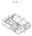
- Fig. 1 roughly shows the whole of a first embodiment of the ink dot printer according to the present invention.
- a platen 12 is arranged in a housing 10 of the ink dot printer, horizontally extending along its rotary center line, and a carrier shaft 14 and a guide shaft 16 are arranged therein parallel to the rotary center line.
- a carriage 18 is mounted on the carrier and guide shafts 14 and 16 to reciprocate along these shafts. The carriage 18 is reciprocated by the well-known carriage moving means (not shown).
- An ink film forming means 22 and a printing head 20 are mounted on the carriage 18.
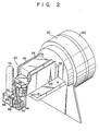
- the ink film forming means 22 has an electromagnet 24 which serves as a means for generating magnetic force, and a pair of magnetic pole plates 26 and 28 are arranged on both sides of the electromagnet 24 to oppose each other. Front end portions 30 and 32 of the paired magnetic pole plates 26 and 28 form a slit 34, which extends substantially in the vertical direction, as shown in Figs. 2 and 3.
- One end portions of plural needles 36 are arranged, adjacent to one another along the longitudinal direction of the-slit 34, in the slit 34 between the paired magnetic pole plates, as shown in Figs. 2 through 4.
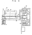
- the other end portions of the plural needles 36 extend through a frame 38 located between the paired magnetic pole plates 26 and 28, as shown in Figs. 2 through 4, and enter into a cover 40 for a printing head 20, as shown in Fig. 3.
- the needles 36 are held relative to one another and freely supported to be reciprocatable in their longitudinal direction by needle guides 42 and 44 arranged in the frame 38, as shown in Fig. 3.
- the position of these needles 36, in this state, is called their first position.
- Plural electromagnets 46 which serve as a means for driving the plural needles 36 are arranged, relative to the plural needles, in the cover for the printing head 20, and armatures 48 are arranged adjacent to the electromagnets 46.
- Each of the needles 36 is urged to its first position, as shown in Figs. 2 through 4, by a return spring 50 wound around it, and the end face of its other end is in contact with the armature 48, as shown in Fig. 3, to separate the armature 48 from the electromagnet 46 while it contacts a stopper 52.
- an ink tank supporting base 54 is attached to the frame 38, as shown in Figs. 2 and 3, extending horizontally just under the front end portions 30 and 32 of the paired magnetic pole plates 26 and 28. Namely, the ink tank supporting base 54 extends in a direction perpendicular to the longitudinal direction of the slit 34.
- a guide member 56 is attached to the ink tank supporting base 54 on one side of the slit 34.
- An ink tank 58 which serves as the magnetic ink storing means, is mounted on the ink tank supporting base 54 and guided by the guide member 56 to freely move horizontally, or in a direction perpendicular to the longitudinal direction of the slit 34.
- the ink tank 58 is substantially L-shaped when viewed from its top.
- a magnetic ink supplying hole 60 is formed on the top surface of the ink tank 58 at the left end portion thereof, and an elongated slot 62, into which the front end portions 30 and 32 of the paired magnetic pole plates 26 and 28 are inserted, is also formed on the top surface of the ink tank 58 at the right end portion thereof.
- the center of the elongated slot 62 is shaped to form an enlarged opening 64 which corresponds to the slit 34 between the paired magnetic pole plates 26 and 28.
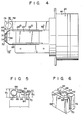
- the boundary between the slot 62 and the enlarged opening 64 is tapered, as shown in Fig. 5.
- An air opening 68 is also formed on the top surface of the ink tank 58.
- This air opening 68 is apart enough from the side wall of the ink tank 58 and the elongated slot 62 so as not to be effected by the rising of a magnetic ink to be stored in the magnetic tank 58, caused by the surface tension of the magnetic ink near around the side wall and the front end portions 30 and 32 of the paired pole plates 26 and 28 inserted in the elongated slot 62.
- This independent air opening 68 is not necessary, but the enlarged opening 64 of the slot 62, which is relatively large, may serve as the air opening for the ink tank 58.
- Dimension W of the left end portion of the ink tank 58 when measured in the vertical direction in Fig. 5, or in the direction in which the needles extend, is set larger than dimension W 2 of the right end portion thereof, and dimension L of the ink tank 58 when measured in the horizontal direction in Fig. 5, or in a direction perpendicular to the longitudinal direction of the slit 34, is larger than the each one of dimensions W, and W 2 .
- the elongated slot 62 extends in the direction of dimension L, that is, in the longitudinal direction of the ink tank 58.
- a guide hole 70 is formed on the right end face of the ink tank 58, as shown in Figs. 5 and 6, extending in the vertical direction, or in the longitudinal direction of the slit 34 between the paired magnetic pole plates 26 and 28, and is tapered at that area 72 thereof which is adjacent to the right end face of the ink tank 58.
- the front end portions 30 and 32 of the paired magnetic pole plates 26 and 28 are inserted into the elongated slot 62 and guide hole 70 of the ink tank 58, and leakage of the magnetic ink from the ink tank 58 through the guide hole 70 thereof is prevented by a well known sealing means (not shown) which is in close contact with the front end portion 32 of the magnetic pole plate 28.
- an ink cartridge 74 is detachably attached to the magnetic ink supplying hole 60 of the inktank 58.
- the inner end face 75 of the magnetic ink supplying hole 60 is located lower in the ink tank 58 than the inner end face 76 of the air opening 68, or the inner surface of the top wall of the ink tank 58.
- the surface of the magnetic ink, supplied from the ink cartridge 74 into the ink tank 58 through the magnetic ink supplying hole 60, is kept at a lower level in the ink tank 58 than the inner end face 76 of the air opening 68.
- a plurality of fiber-like lines 78 are housed in the ink tank 58, as shown in Figs. 3 and 7. These lines 78 extend in the horizontal direction in Fig. 7, or in the longitudinal direction of the ink tank 58, and are slightly separated from one another in the vertical direction in Fig. 7. However, they are not located just under the magnetic ink supplying hole 60 of the ink tank 58. They may be made of horse or racoon dog hairs or filaments of synthetic resin having a diameter of 100 ⁇ 50 u.
- a recording paper 80 is mounted on the platen 12 inside the housing 10 shown in Fig. 1.
- a main switch (not shown) arranged on the housing 10 is turned ON, current is supplied to the electromagnet 24, so that the magnetic ink in the ink tank 58 is drawn into the slit 34 between the front end portions 30 and 32 of the paired magnetic pole plates 26 and 28 due to the effect of the magnetic field produced in the slit 34 by magnetic flux generated between the paired magnetic pole plates 26 and 28, thereby forming a magnetic ink film 82 in the slit 34, as shown in Fig. 8.
- the magnetic ink film 82 in the slit 34 immerses one end portions of the needles 36, which are located at their first position as shown in Figs. 2 through 4.
- the magnetic ink 77 swells because of inertial force in the ink tank 58, caused when the carriage 18 starts and stops its movement, and a sudden repeat of this movement causes the swelling of the magnetic ink 77 to become more remarkable.
- the plural thin lines 78 arranged inside the ink tank 58 function as the wave eliminating means, thereby preventing the swelling of the magnetic ink 77 in the ink tank 58 from becoming more remarkable.
- the inner end face 75 of the magnetic ink supplying hole 60 is set lower in level in the ink tank 58 than the inner end face 76 of the air opening 68, and a space is created in the ink tank 58 between the surface of the magnetic ink 77 and the inner end face 76 of the air opening 68, as shown in Fig. 7. Therefore, the magnetic ink 77 in the ink tank 58 will not jet outside through the air opening 68 and enlarged opening 64 of the slot 62 even when the magnetic ink 77 swells more or less in the ink tank 58. Furthermore, the thin lines 78 can achieve high effect particularly as the wave eliminating means, since they extend in the longitudinal direction of the ink tank 58, or in the direction in which the carriage 18 is moved.
- this wave eliminating means and the position of the inner end face 75 of the magnetic ink supplying hole 60 in the ink tank 58 are extremely effective in preventing the swelling of the magnetic ink 77 in the ink tank 58, which is caused even when the ink dot printer is being moved, and also effective in preventing the jetting of the magnetic ink 77 through the air opening 68 and enlarged opening 64 of the slot 62, which is caused by this swelling of the magnetic ink 77.
- the wevel and amount of magnetic ink 77 drawn from the ink tank 58 to the slit 34 does not change because the surface of the magnetic ink 77 does not swell but is kept at a certain level in the ink tank 58. Therefore, the amount of magnetic ink 77 stuck on those one end portions of the needles 36 which are immersed in the magnetic ink film 82 in the slit 34 is kept constant to usually form dots with a certain density.
- the supply of magnetic ink 77 into the ink tank 58 can be achieved again by replacing the ink cartridge 74 with a new one when the ink cartridge 74 becomes empty and the magnetic ink 77 cannot be supplied to the ink tank 58.
- Attached to the ink cartridge 74 is the well-known cap which will be stuck and broken when the ink cartridge 74 is set in the magnetic ink supplying hole 60 of the ink tank 58.
- the connection between the ink tank 58 and the front end portions 30 and 32 of the paired magnetic pole plates 26 and 28 can be released, as shown in Fig. 11, by only moving the ink tank 58 in left direction in Fig. 2, thereby enabling the ink tank 58 to be easily detached from the ink dot printer.
- the ink tank 58 When the ink tank 58 is mounted on the ink tank supporting. base 54 and moved along the guide member 56 in the right direction in Fig. 11 after having cleaned the ink tank 58, the front end portions 30 and 32 of the paired magnetic pole plates 26 and 28 are guided into the elongated slot 62 of the ink tank 58 through the guide hole 70. At this time, one of the front end portions 30 strikes the dead end of the slot 62 to thereby stop the ink tank 58.
- the enlarged opening 64 of the slot 62 corresponds, in this state, to the slit 34 between the paired magnetic pole plates 26 and 28, as shown in Fig. 2.
- the guide hole 70 is closed by the other front end portion 32, and the leakage of the magnetic ink 77 through the guide hole 70 can be prevented by the combination of the front end portion 32 and the well-known sealing means, as described above. Since the boundary 66 between the slot 62 and its enlarged opening 64 and that area 72 of the guide hole 70 adjacent to the right end face of the ink tank 58 are tapered, the front end portions 30 and 32 of the paired magnetic pole plates 26 and 28 can be easily fitted into and detached from the guide hole 70 and the slot 62.
- FIG. 12 through 14 A second embodiment of the ink dot printer according to the present invention will be described referring to Figs. 12 through 14.
- the same parts as those in the first embodiment described in reference to Figs. 1 through 11 will be represented by same reference numerals, and the description of these parts will be omitted.
- the ink tank 58 is made flatter, and neither the independent air opening 68 nor the guide hole 70, which is to be continuous to the slot 62 and into which the front end portions 30 and 32 of the paired magnetic pole plates 26 and 28 are to be fitted, is provided.
- the enlarged opening 64 of the slot 62 serves as the air opening for the ink tank 58 in this case.
- the connection between the front end portions 30 and 32 of the paired magnetic pole plates 26 and 28 and the ink tank 58 can be attained in such a way that the ink tank 58 is moved along the longitudinal direction of the slit 34. This allows the front end portions 30 and 32 of the paired magnetic pole plates 26 and 28 to be fitted into the slot 62 of the ink tank 58, as shown in Fig. 13.
- An electromagnet 84 is fixed to the outer surface of bottom wall of the ink tank 58 to face the slit 34 in the longitudinal direction of the slit 34 between the paired magnetic pole plates 26 and 28, as shown in Fig. 13.
- a sleeve 86 which is detachably fitted into the magnetic ink supplying hole 60 of the ink tank 58 is formed on the underside of the ink cartridge 74, and a spring 88 and a plate-like plug 90 urged downward by the spring 88 are housed in the sleeve 86.
- the plug 90 has a push rod 94 which extends downward to project outside through a discharge opening 92 formed on the bottom end face of the sleeve 86, and a plurality of cut-away portions 96 are formed on the outer circumference of the plug 90, as shown in particular detail in Fig. 14.
- the radius of a circle, formed by connecting inner ends of these cutaway portions 96 when viewed radially, is set larger than that of the discharge opening 92.
- the push rod 94 strikes the inner surface of the bottom wall of the ink tank 58 to separate the plug 90 from the discharge opening 92 against the spring 88, thereby allowing the magnetic ink 77 in the ink cartridge 74 to flow into the ink tank 58 through the cutaway portions 96 of the plug 90 and the discharge opening 92 of the sleeve 86.
- the flow of the magnetic ink 77 into the ink tank 58 is stopped when the surface of the magnetic ink 77 in the ink tank 58 reaches the discharge opening 92 of the sleeve 86, or when it reaches the inner end face 75 of the magnetic ink supplying hole 60, as shown in Fig. 13. Thereafter, the surface of the magnetic ink 77 in the ink tank 58 is kept at the same level as the discharge opening 92 of the sleeve 86 of the ink cartridge 74 until the ink cartridge 74 is emptied.
- the ink cartridge 74 can be detached from the magnetic ink supplying hole 60 of the ink tank 58 even when the magnetic ink 77 is still left in the ink cartridge 74. This is because the push rod 94 of the plug 90 is separated from the inner surface of the bottom wall of the ink tank 58 when the sleeve 86 of the ink cartridge 74 is separated from the magnetic ink supplying hole 60 of the ink tank 58, and because the plug 90 is pressed onto the bottom wall of the sleeve 86 by the spring 88 to close the discharge opening 92 to thereby prevent the magnetic ink 77 from being scattered outside the ink cartridge 74.
- the inktank 58 may be provided with the guide hole 70 which guides the front end portions 30 and 32 of the paired magnetic pole plates 26 and 28 into the slot 62 in a direction perpendicular to the longitudinal direction of the slit 34, and the wave eliminating means which comprises a plurality of the fiber-like thin lines 78, for example, may be arranged in the ink tank 58.
- a sponge for example, may be used instead of the plural fibre-likethin lines 78.
- nets 98 may be arranged, adjacent to one another in the longitudinal direction of the needles 36, in the ink tank 58, as shown in Figs. 15 and 16.
- a mass 100 formed by entangling fiber-like short thin lines with one another, as shown in Fig. 17, may be used.
- a basket 104 provided with a slot 102 into which the front end portions 30 and 32 of the paired °magnetic pole plates 26 and 28 are to be fitted, as shown in Fig. 18, may be used.
- the net 98 is less dense in the area adjacent to the slit 34 between the front end portions 30 and 32 of the paired magnetic pole plates 26, 28 than in its other area.
- the magnetic ink 77 which has formed the film 82 in the slit 34 can be quickly collected into the ink tank 58 through the enlarged opening 64 by ceasing the magnetic flux between the paired magnetic pole plates 26 and 28, even in the case where the wave eliminating means is arranged in the ink tank 58.
- the nets 98 are not located just underthe magnetic ink supplying hole 60 for the purpose of allowing the magnetic ink 77 to be quickly supplied from the ink cartridge 74 to the ink tank 58 through the magnetic ink supplying hole 60.
- partition plates 108 each having through-holes 106 may be arranged in the ink tank 58, extending in a direction perpendicular to the longitudinal direction of the ink tank 58, as shown in Figs. 19 and 20.
- the through-hole 106 has no limitation in shape but may be made to have an easily-processed shape. Namely, they may be made circular, for example, as shown in Fig. 21.
- the electromagnet 84 arranged just under the slit 34 and on the outer surface of the bottom wall of the ink tank 58 for forcedly collect the magnetic ink 77 forming the film 88 in the slit 34 from the slit 34 into the ink tank 58 may be used in the first embodiment shown in Figs. 1 to 11 and in the various modifications shown in Figs. 15 to 21.
Landscapes
- Impact Printers (AREA)
Description
- The present invention relates to an ink dot printer as is defined in the preambles of
claims 1 and 10. - An ink dot printer as defined in the preambles of the
claims 1 and 10 is known (IBM Technical Disclosure Bulletin, Vol. 18, No. 9, February 1976, page 2761). A drawback of said known ink dot printer is that it does not operate always sufficiently since the printing density varies during operation. - Thermal or wire dot printers are usually used as ink dot printers. In the case of wire dot printers plural needles are selectively driven to directly strike a pressure-sensitive manifold paper on the platen with their end faces or indirectly strike a recording paper with their end faces through a printing ribbon interposed between the paper and needles so as to form dots thereon, thereby enabling symbols, such as characters and numerals, to be printed by gathering these dots. With the conventional wire dot printer having the above-described arrangement, however, a loud noise is generated at the time of printing symbols on the pressure-sensitive manifold paper. In addition, paper except the pressure-sensitive manifold type can be used, and the expensive printing ribbon must frequently be replaced by a new one. The expensive printing ribbon must be used in the thermal dot printers.
- In order to eliminate the drawbacks of the conventional thermal or wire dot printers, there have been proposed various kinds of ink dot printers wherein one end portions of the plural needles are arranged in a slit formed by a pair of magnetic pole plates, the paired magnetic pole plates are magnetized to draw magnetic ink supplied from the magnetic ink storing means into the slit and stick the magnetic ink onto one end portions of the plural needles, and these plural needles are then selectively driven to transfer the magnetic ink on their end faces onto the recording paper on the platen so as to form dots thereon. With the ink dot printer of this type, however, the process of supplying the liquid magnetic ink to the magnetic ink storing means is troublesome, and it often happens that the magnetic ink is caused to overflow from the magnetic ink supplying hole of the magnetic ink storing means in the course of this magnetic ink supplying process, or that the magnetic ink is caused to splash over the magnetic ink storing means before it reaches the magnetic ink supplying hole.
- Further, the liquid magnetic ink whose viscosity has increased because it has been subjected to air in the slit for a relatively long time, when the paired magnetic pole plates were de-energized at the time of non-use, cannot be quickly collected into the magnetic ink storing means and part of it remains in the slit due to its surface tension and dries. The dried magnetic ink thus stuck to the slit is likely to prevent the liquid magnetic ink from being drawn from the magnetic ink storing means into the slit and also prevent the operation of the needles, whose one end portions are arranged in the slit, when the ink dot printer is used again.
- Furthermore, when the ink dot printer is suddenly moved or a carriage on which the paired magnetic pole plates; magnetism generating means, plural needles, driving means, and magnetic ink storing means are mounted is suddenly moved to form dots along the longitudinal center line of the platen, the magnetic ink swells in the magnetic ink storing means to sometimes jet outside through the air opening of the magnetic ink storing means;
- Still furthermore, when the ink dot printer is left unused for a long time, the magnetic ink in the magnetic ink storing means dries at its surface area where it contacts air and sticks to the inner wall of the magnetic ink storing means. The dried magnetic ink thus stuck to the inner wall of the magnetic ink storing means must be removed by detaching the magnetic ink storing means from the ink dot printer and washing it. In the case of the conventional ink dot printer, however, the longitudinal direction of the slit is substantially vertical, and the paired magnetic pole plates are inserted into and connected with the magnetic ink storing means in the longitudinal direction of the slit. Therefore, the process of releasing the connection between the paired magnetic pole plates and the magnetic ink storing means to detach the magnetic ink storing means from the ink dot printer becomes troublesome.
- It is also known an ink delivery system (US-A-4 353 654) employing capillary member for delivering ink from a container directly to the tips of the reciprocating print wires for ink transfer to a print receiving medium. Adjustment is provided for regulating the surface contact area between an ink container capillary member and a print head capillary member to regulate ink flow in order to accommodate printing speed and compensate for any factors which may alter ink flow, whether they be to cause more or less rapid ink flow. In a preferred embodiment of the said system, the ink container capillary member is moved relative to the print head capillary member. The capillary members are comprised of a porous material. Adjustment of ink flow is simplified through the provison of an easily movable handle arm and cooperating serrated slot for simply and rapidly adjusting the interface between the cooperating capillary members through which interface the ink is caused to flow.
- The present invention starts from an ink dot printer defined in the preambles of
claims 1 and 10 and intends to eliminate the above-mentioned drawbacks of this prior art. Thus, the object of the present invention is to avoid a variation in printing density. - This object of the present invention is achieved by the features of the characterizing parts of
claims 1 and 10, respectively. - Further advantageously developments of the present invention result from the subclaims.
- The advantages of the invention are the provision of an ink dot printer capable of smoothly drawing the magnetic ink from the magnetic ink storing means into the slit and also smoothly operating the needles whose one end portions are arranged in the slit, but without causing the magnetic ink to be dried and stuck to the slit even at the time of re-use of the ink dot printer after non-use thereof. A further advantage results from the provision of an ink dot printer wherein the magnetic ink storing means can be easily detached from the paired magnetic pole plates.
- Furthermore, the magnetic ink is prevented from swelling inside the magnetic ink storing means and jetting outside the magnetic ink storing means through its air opening, even when the ink dot printer is suddenly moved or the carriage (on which magnetic pole plates, magnetic generating means, plural needles, driving means and magnetic ink storing means are mounted) is suddenly moved on a line along the longitudinal center line of the platen.
- As is stated in claim 1 the magnetic ink supplying hole maintains ink level in magnetic ink storing means invariably constant until ink cartridge becomes empty. Moreover the magnetic ink supplying hole serves to prevent an overflow of ink out of air openings. Wave eliminating means serve to prevent ink in magnetic ink storing means from splashing out of air openings due to stirring or swelling of ink resulting from the reciprocatory movement of a printing head and to prevent an ink level in ink cartridge from being stirred. Namely variation in the ink level in cartridge would result in a variation in the thickness of ink film formed in a slit defined between the pair of magnetic pole plates. This on the other hand would cause a variation in the amount of ink deposited on the forward ends of needles and eventually a variation in printing density. The above featuring aspect of the present invention is very important to ink dot printers.
- Wave eliminating means according to the present invention are formed of a material with a plurality of through holes in which ink is retained. The use of that wave elimination means assures a considerable advantage over that obtained on baffle plates of US Patent No. 4 353 654.
- None of the references cited neither disclose, nor suggest the aforementioned wave eliminating means. These wave eliminating means will reduce the extent of stirring or swelling of the magnetic ink produced in magnetic ink storing means when ink film in the said slit is returned to magnetic ink storing means. As a result the swelling or stirring of the ink can immediately disappear without involving any wave resonance. It is thus possible to prevent the ink from being splashed out of magnetic ink storing means.
- In the ink dot printer as recited in
claim 10, the said magnet serves to prevent magnetic ink from stirring and swelling in ink storing means and, consequently, to prevent the ink from being splashed out of air openings or to prevent the level of ink from being changed. As a result, it is possible to prevent a variation in the density of printing. Thereby the advantage as set forth above is also obtainable by means of the aforementioned magnet recited inclaim 10. - This invention can be more fully understood from the following detailed description when taken in conjunction with the accompanying drawings, in which:
- Fig. 1 is a perspective view roughly showing the whole of a first embodiment of the ink dot printer according to the present invention;
- Fig. 2 is a perspective view roughly showing the whole of a printing head and an ink film forming means shown in Fig. 1;
- Fig. 3 is a side view roughly showing the printing head and ink film forming means in Fig. 2 partly cut off;
- Fig. 4 is a plane view roughly showing the printing head and ink film forming means in Fig. 2;
- Fig. 5 is a plane view showing only an ink tank in Fig. 2;
- Fig. 6 is a perspectie view showing the right end portion of the ink tank in Fig. 5 enlarged;
- Fig. 7 is a sectional view taken along the line VII-VII in Fig. 4;
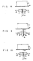
- Fig. 8 is a plane view showing, in enlarged scale a condition under which magnetic ink film is formed in the slit between the paired magnetic pole plates, and under which a needle is located at the first position;
- Fig. 9 is a plane view showing a condition under which the needle in Fig. 8 is located at the second position;
- Fig. 10 is a plane view showing a condition under which the needle in Fig. 9 is returned to the first position after forming a dot of the magnetic ink on a recording paper on a platen;
- Fig. 11 is a perspective view showing the connection between the ink tank and the front end portions of the paired magnetic pole plates released;
- Fig. 12 is a perspective view roughly showing, in enlarged scale, the whole of a printing head and an ink film forming means in a second embodiment of the ink dot printer according to the present invention, and also showing connections between the ink tank and the front end portions of the paired magnetic pole plates and between the ink tank and an ink cartridge released;
- Fig. 13 is a front view roughly showing, partly cut off, the ink tank in Fig. 12 connected with the front end portions of the paired magnetic pole plates and with the ink cartridge;
- Fig. 14 is a perspective view showing only a plug for the ink cartridge in Fig. 13;
- Fig. 15 is a sectional view, similar to Fig. 7, showing a variation of the wave eliminating means arranged inside the ink tank in Fig. 7;
- Fig. 16 is a sectional view taken along the line XVI-XVI in Fig. 15;
- Figs. 17 and 18 are perspective views showing other variations of the wave eliminating means;
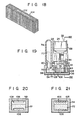
- Fig. 19 is a sectional view, similar to Fig. 7, roughly showing a further variation of the wave eliminating means arranged inside the ink tank in Fig. 7;
- Fig. 20 is a sectional view taken along the line XX-XX in Fig. 19: and
- Fig. 21 is a sectional view, similar to Fig. 20, showing a variation of the wave eliminating means in Fig. 20.
- Fig. 1 roughly shows the whole of a first embodiment of the ink dot printer according to the present invention. A
platen 12 is arranged in ahousing 10 of the ink dot printer, horizontally extending along its rotary center line, and acarrier shaft 14 and aguide shaft 16 are arranged therein parallel to the rotary center line. Acarriage 18 is mounted on the carrier and guideshafts carriage 18 is reciprocated by the well-known carriage moving means (not shown). An inkfilm forming means 22 and aprinting head 20 are mounted on thecarriage 18. - As shown in Figs. 2 through 4, the ink film forming means 22 has an
electromagnet 24 which serves as a means for generating magnetic force, and a pair ofmagnetic pole plates electromagnet 24 to oppose each other.Front end portions magnetic pole plates slit 34, which extends substantially in the vertical direction, as shown in Figs. 2 and 3. - One end portions of
plural needles 36 are arranged, adjacent to one another along the longitudinal direction of the-slit 34, in theslit 34 between the paired magnetic pole plates, as shown in Figs. 2 through 4. The other end portions of theplural needles 36 extend through aframe 38 located between the pairedmagnetic pole plates cover 40 for aprinting head 20, as shown in Fig. 3. Theneedles 36 are held relative to one another and freely supported to be reciprocatable in their longitudinal direction by needle guides 42 and 44 arranged in theframe 38, as shown in Fig. 3. The position of theseneedles 36, in this state, is called their first position. -
Plural electromagnets 46 which serve as a means for driving the plural needles 36 are arranged, relative to the plural needles, in the cover for theprinting head 20, andarmatures 48 are arranged adjacent to theelectromagnets 46. Each of theneedles 36 is urged to its first position, as shown in Figs. 2 through 4, by areturn spring 50 wound around it, and the end face of its other end is in contact with thearmature 48, as shown in Fig. 3, to separate thearmature 48 from theelectromagnet 46 while it contacts astopper 52. - In the case of this ink dot printer, an ink
tank supporting base 54 is attached to theframe 38, as shown in Figs. 2 and 3, extending horizontally just under thefront end portions magnetic pole plates tank supporting base 54 extends in a direction perpendicular to the longitudinal direction of theslit 34. Aguide member 56 is attached to the inktank supporting base 54 on one side of theslit 34. Anink tank 58, which serves as the magnetic ink storing means, is mounted on the inktank supporting base 54 and guided by theguide member 56 to freely move horizontally, or in a direction perpendicular to the longitudinal direction of theslit 34. - The
ink tank 58 is substantially L-shaped when viewed from its top. A magneticink supplying hole 60 is formed on the top surface of theink tank 58 at the left end portion thereof, and anelongated slot 62, into which thefront end portions magnetic pole plates ink tank 58 at the right end portion thereof. The center of theelongated slot 62 is shaped to form anenlarged opening 64 which corresponds to theslit 34 between the pairedmagnetic pole plates slot 62 and theenlarged opening 64 is tapered, as shown in Fig. 5. Anair opening 68 is also formed on the top surface of theink tank 58. Thisair opening 68 is apart enough from the side wall of theink tank 58 and theelongated slot 62 so as not to be effected by the rising of a magnetic ink to be stored in themagnetic tank 58, caused by the surface tension of the magnetic ink near around the side wall and thefront end portions pole plates elongated slot 62. Thisindependent air opening 68, however, is not necessary, but theenlarged opening 64 of theslot 62, which is relatively large, may serve as the air opening for theink tank 58. - Dimension W, of the left end portion of the
ink tank 58 when measured in the vertical direction in Fig. 5, or in the direction in which the needles extend, is set larger than dimension W2 of the right end portion thereof, and dimension L of theink tank 58 when measured in the horizontal direction in Fig. 5, or in a direction perpendicular to the longitudinal direction of theslit 34, is larger than the each one of dimensions W, and W2. Theelongated slot 62 extends in the direction of dimension L, that is, in the longitudinal direction of theink tank 58. - A
guide hole 70 is formed on the right end face of theink tank 58, as shown in Figs. 5 and 6, extending in the vertical direction, or in the longitudinal direction of theslit 34 between the pairedmagnetic pole plates area 72 thereof which is adjacent to the right end face of theink tank 58. - As shown in Figs. 2 and 3, the
front end portions magnetic pole plates elongated slot 62 and guidehole 70 of theink tank 58, and leakage of the magnetic ink from theink tank 58 through theguide hole 70 thereof is prevented by a well known sealing means (not shown) which is in close contact with thefront end portion 32 of themagnetic pole plate 28. - As shown particularly in Fig. 7, an
ink cartridge 74 is detachably attached to the magneticink supplying hole 60 of theinktank 58. The inner end face 75 of the magneticink supplying hole 60 is located lower in theink tank 58 than the inner end face 76 of theair opening 68, or the inner surface of the top wall of theink tank 58. The surface of the magnetic ink, supplied from theink cartridge 74 into theink tank 58 through the magneticink supplying hole 60, is kept at a lower level in theink tank 58 than the inner end face 76 of theair opening 68. - A plurality of fiber-
like lines 78 are housed in theink tank 58, as shown in Figs. 3 and 7. Theselines 78 extend in the horizontal direction in Fig. 7, or in the longitudinal direction of theink tank 58, and are slightly separated from one another in the vertical direction in Fig. 7. However, they are not located just under the magneticink supplying hole 60 of theink tank 58. They may be made of horse or racoon dog hairs or filaments of synthetic resin having a diameter of 100 µ50 u. - A
recording paper 80 is mounted on theplaten 12 inside thehousing 10 shown in Fig. 1. - When a main switch (not shown) arranged on the
housing 10 is turned ON, current is supplied to theelectromagnet 24, so that the magnetic ink in theink tank 58 is drawn into theslit 34 between thefront end portions magnetic pole plates slit 34 by magnetic flux generated between the pairedmagnetic pole plates magnetic ink film 82 in theslit 34, as shown in Fig. 8. Themagnetic ink film 82 in theslit 34 immerses one end portions of theneedles 36, which are located at their first position as shown in Figs. 2 through 4. - When a key on the keyboard (not shown) is pushed, current is supplied to the
electromagnet 46 which corresponds to the key, and theelectromagnet 46 draws itscorreponding armature 48 against the action of thereturn spring 50 would around theneedle 36. Theneedle 36 which corresponds to thearmature 48 drawn by theelectromagnet 46 projects from themagnetic ink film 82 in theslit 34 toward therecording paper 80, as shown in Fig. 9, slightly touches therecording paper 80 on theplaten 12, and forces themagnetic ink 77 on its one end face onto therecording paper 80. The position of theneedle 36 in this state is regarded as its second position. Themagnetic ink 77 stuck on therecording paper 80 by theneedle 36 which is at the second position, as shown in Fig. 9, continues to adhere to therecording paper 80 to form a dot of themagnetic ink 77 even after theneedle 36 is returned to the first position by the action of thereturn spring 50, as shown in Fig. 10. - When the
carriage 18 is moved along the carrier and guideshafts 14 and 16 to form a plurality of dots on therecording paper 80 along the longitudinal center line of theplaten 12, themagnetic ink 77 swells because of inertial force in theink tank 58, caused when thecarriage 18 starts and stops its movement, and a sudden repeat of this movement causes the swelling of themagnetic ink 77 to become more remarkable. In the case of this example, however, the pluralthin lines 78 arranged inside theink tank 58 function as the wave eliminating means, thereby preventing the swelling of themagnetic ink 77 in theink tank 58 from becoming more remarkable. Further, the inner end face 75 of the magneticink supplying hole 60 is set lower in level in theink tank 58 than the inner end face 76 of theair opening 68, and a space is created in theink tank 58 between the surface of themagnetic ink 77 and the inner end face 76 of theair opening 68, as shown in Fig. 7. Therefore, themagnetic ink 77 in theink tank 58 will not jet outside through theair opening 68 and enlarged opening 64 of theslot 62 even when themagnetic ink 77 swells more or less in theink tank 58. Furthermore, thethin lines 78 can achieve high effect particularly as the wave eliminating means, since they extend in the longitudinal direction of theink tank 58, or in the direction in which thecarriage 18 is moved. Needless to say, this wave eliminating means and the position of the inner end face 75 of the magneticink supplying hole 60 in theink tank 58 are extremely effective in preventing the swelling of themagnetic ink 77 in theink tank 58, which is caused even when the ink dot printer is being moved, and also effective in preventing the jetting of themagnetic ink 77 through theair opening 68 and enlarged opening 64 of theslot 62, which is caused by this swelling of themagnetic ink 77. In addition, the wevel and amount ofmagnetic ink 77 drawn from theink tank 58 to theslit 34 does not change because the surface of themagnetic ink 77 does not swell but is kept at a certain level in theink tank 58. Therefore, the amount ofmagnetic ink 77 stuck on those one end portions of theneedles 36 which are immersed in themagnetic ink film 82 in theslit 34 is kept constant to usually form dots with a certain density. - Moreover, the supply of
magnetic ink 77 into theink tank 58 can be achieved again by replacing theink cartridge 74 with a new one when theink cartridge 74 becomes empty and themagnetic ink 77 cannot be supplied to theink tank 58. Attached to theink cartridge 74 is the well-known cap which will be stuck and broken when theink cartridge 74 is set in the magneticink supplying hole 60 of theink tank 58. - When the main switch (not shown) is turned OFF after the ink dot printer has finished the printing process, current supplied to the
electromagnet 24 is stopped and the magnetic flux between the pairedmagnetic pole plates magnetic ink 77 which has formed themagnetic ink film 82 in theslit 34 is collected into theink tank 58 due to its weight and the capillary action of thethin lines 78 in theink tank 58. - When the ink dot printer is left unused for a long time, causing the
magnetic ink 77 to dry and stick to the inner wall of theink tank 58, and theink tank 58 has to be cleaned accordingly, the connection between theink tank 58 and thefront end portions magnetic pole plates ink tank 58 in left direction in Fig. 2, thereby enabling theink tank 58 to be easily detached from the ink dot printer. - When the
ink tank 58 is mounted on the ink tank supporting.base 54 and moved along theguide member 56 in the right direction in Fig. 11 after having cleaned theink tank 58, thefront end portions magnetic pole plates elongated slot 62 of theink tank 58 through theguide hole 70. At this time, one of thefront end portions 30 strikes the dead end of theslot 62 to thereby stop theink tank 58. Theenlarged opening 64 of theslot 62 corresponds, in this state, to theslit 34 between the pairedmagnetic pole plates guide hole 70 is closed by the otherfront end portion 32, and the leakage of themagnetic ink 77 through theguide hole 70 can be prevented by the combination of thefront end portion 32 and the well-known sealing means, as described above. Since theboundary 66 between theslot 62 and itsenlarged opening 64 and thatarea 72 of theguide hole 70 adjacent to the right end face of theink tank 58 are tapered, thefront end portions magnetic pole plates guide hole 70 and theslot 62. - A second embodiment of the ink dot printer according to the present invention will be described referring to Figs. 12 through 14. The same parts as those in the first embodiment described in reference to Figs. 1 through 11 will be represented by same reference numerals, and the description of these parts will be omitted.
- As shown in Fig. 12, the
ink tank 58 is made flatter, and neither theindependent air opening 68 nor theguide hole 70, which is to be continuous to theslot 62 and into which thefront end portions magnetic pole plates enlarged opening 64 of theslot 62 serves as the air opening for theink tank 58 in this case. The connection between thefront end portions magnetic pole plates ink tank 58 can be attained in such a way that theink tank 58 is moved along the longitudinal direction of theslit 34. This allows thefront end portions magnetic pole plates slot 62 of theink tank 58, as shown in Fig. 13. - An
electromagnet 84 is fixed to the outer surface of bottom wall of theink tank 58 to face theslit 34 in the longitudinal direction of theslit 34 between the pairedmagnetic pole plates - As shown in Fig. 13, a
sleeve 86 which is detachably fitted into the magneticink supplying hole 60 of theink tank 58 is formed on the underside of theink cartridge 74, and aspring 88 and a plate-like plug 90 urged downward by thespring 88 are housed in thesleeve 86. Theplug 90 has apush rod 94 which extends downward to project outside through adischarge opening 92 formed on the bottom end face of thesleeve 86, and a plurality of cut-awayportions 96 are formed on the outer circumference of theplug 90, as shown in particular detail in Fig. 14. The radius of a circle, formed by connecting inner ends of thesecutaway portions 96 when viewed radially, is set larger than that of thedischarge opening 92. - When the
sleeve 86 is fitted into the magneticink supplying hole 60 of theink tank 58, thepush rod 94 strikes the inner surface of the bottom wall of theink tank 58 to separate theplug 90 from thedischarge opening 92 against thespring 88, thereby allowing themagnetic ink 77 in theink cartridge 74 to flow into theink tank 58 through thecutaway portions 96 of theplug 90 and the discharge opening 92 of thesleeve 86. The flow of themagnetic ink 77 into theink tank 58 is stopped when the surface of themagnetic ink 77 in theink tank 58 reaches the discharge opening 92 of thesleeve 86, or when it reaches the inner end face 75 of the magneticink supplying hole 60, as shown in Fig. 13. Thereafter, the surface of themagnetic ink 77 in theink tank 58 is kept at the same level as the discharge opening 92 of thesleeve 86 of theink cartridge 74 until theink cartridge 74 is emptied. Thefront end portions magnetic pole plates slot 62 of theink tank 58 are immersed this time in themagnetic ink 77 in theink tank 58, as shown in Fig. 13. This time, a space, which serves as the air opening, is also created between the surface of themagnetic ink 77 and the inner end face 76 of theenlarged opening 64 of theink tank 58, that is, the inner surface of the top wall of theink tank 58. - When the main switch (not shown) is turned OFF after the ink dot printer has finished the printing process, current supply to the
electromagnet 24 is stopped and the magnetic flux between the pairedmagnetic pole plates magnetic ink 77 which has formed thefilm 82 in theslit 34, as shown in Fig. 8, is collected, due to its weight, into theink tank 58 through theenlarged opening 64. In the case of this second embodiment, however, current is supplied to theelectromagnet 84 of theink tank 58 as soon as the main switch (not shown) is turned OFF, and themagnetic ink 77 which has formed thefilm 82 in theslit 34 is therefore forcedly drawn into theink tank 58 thanks to magnetic force generated by theelectromagnet 84 of theink tank 58. Even when the viscosity of themagnetic ink 77 which forms thefilm 82 in theslit 34 increases because it has been subject to air for a relatively long time, it is not left in theslit 34 regardless of its surface tension. - The
ink cartridge 74 can be detached from the magneticink supplying hole 60 of theink tank 58 even when themagnetic ink 77 is still left in theink cartridge 74. This is because thepush rod 94 of theplug 90 is separated from the inner surface of the bottom wall of theink tank 58 when thesleeve 86 of theink cartridge 74 is separated from the magneticink supplying hole 60 of theink tank 58, and because theplug 90 is pressed onto the bottom wall of thesleeve 86 by thespring 88 to close thedischarge opening 92 to thereby prevent themagnetic ink 77 from being scattered outside theink cartridge 74. - Also in the case of the second embodiment, the
inktank 58 may be provided with theguide hole 70 which guides thefront end portions magnetic pole plates slot 62 in a direction perpendicular to the longitudinal direction of theslit 34, and the wave eliminating means which comprises a plurality of the fiber-likethin lines 78, for example, may be arranged in theink tank 58. - As the wave eliminating means which prevents the
magnetic ink 77 from swelling in theink tank 58, a sponge, for example, may be used instead of the plural fibre-likethin lines 78. Or nets 98 may be arranged, adjacent to one another in the longitudinal direction of theneedles 36, in theink tank 58, as shown in Figs. 15 and 16. Or a mass 100 formed by entangling fiber-like short thin lines with one another, as shown in Fig. 17, may be used. Or abasket 104 provided with aslot 102 into which thefront end portions magnetic pole plates - The net 98 is less dense in the area adjacent to the
slit 34 between thefront end portions magnetic pole plates magnetic ink 77 which has formed thefilm 82 in theslit 34 can be quickly collected into theink tank 58 through theenlarged opening 64 by ceasing the magnetic flux between the pairedmagnetic pole plates ink tank 58. Thenets 98 are not located just underthe magneticink supplying hole 60 for the purpose of allowing themagnetic ink 77 to be quickly supplied from theink cartridge 74 to theink tank 58 through the magneticink supplying hole 60. - As the wave eliminating means, which prevents the
magnetic ink 77 from swelling in theink tank 58,partition plates 108 each having through-holes 106, for example, may be arranged in theink tank 58, extending in a direction perpendicular to the longitudinal direction of theink tank 58, as shown in Figs. 19 and 20. The through-hole 106 has no limitation in shape but may be made to have an easily-processed shape. Namely, they may be made circular, for example, as shown in Fig. 21. - The
electromagnet 84 arranged just under theslit 34 and on the outer surface of the bottom wall of theink tank 58 for forcedly collect themagnetic ink 77 forming thefilm 88 in theslit 34 from theslit 34 into theink tank 58 may be used in the first embodiment shown in Figs. 1 to 11 and in the various modifications shown in Figs. 15 to 21.
Claims (15)
characterized in that:
Applications Claiming Priority (12)
| Application Number | Priority Date | Filing Date | Title |
|---|---|---|---|
| JP103958/83 | 1983-06-10 | ||
| JP10395883A JPS59229350A (en) | 1983-06-10 | 1983-06-10 | Dot printer |
| JP19382583A JPS6083858A (en) | 1983-10-17 | 1983-10-17 | dot printer |
| JP193825/83 | 1983-10-17 | ||
| JP19945083A JPS6090774A (en) | 1983-10-24 | 1983-10-24 | dot printer |
| JP199450/83 | 1983-10-24 | ||
| JP205619/83 | 1983-10-31 | ||
| JP20561983A JPS6096464A (en) | 1983-10-31 | 1983-10-31 | Dot printer |
| JP207161/83 | 1983-11-04 | ||
| JP20716183A JPS6099668A (en) | 1983-11-04 | 1983-11-04 | Dot printer |
| JP214407/83 | 1983-11-15 | ||
| JP21440783A JPS60105550A (en) | 1983-11-15 | 1983-11-15 | Dot printer |
Publications (3)
| Publication Number | Publication Date |
|---|---|
| EP0128557A2 EP0128557A2 (en) | 1984-12-19 |
| EP0128557A3 EP0128557A3 (en) | 1985-08-07 |
| EP0128557B1 true EP0128557B1 (en) | 1989-09-13 |
Family
ID=27552177
Family Applications (1)
| Application Number | Title | Priority Date | Filing Date |
|---|---|---|---|
| EP84106579A Expired EP0128557B1 (en) | 1983-06-10 | 1984-06-08 | Ink dot printer |
Country Status (3)
| Country | Link |
|---|---|
| US (1) | US4552472A (en) |
| EP (1) | EP0128557B1 (en) |
| DE (1) | DE3479714D1 (en) |
Families Citing this family (3)
| Publication number | Priority date | Publication date | Assignee | Title |
|---|---|---|---|---|
| US4696589A (en) * | 1984-10-26 | 1987-09-29 | Tokyo Electric Co., Ltd. | Ink-dot printer |
| JP5277540B2 (en) * | 2007-01-09 | 2013-08-28 | 富士ゼロックス株式会社 | Magnetic polymer particles, production method thereof, water dispersion, cartridge, and image forming apparatus |
| US8894181B2 (en) * | 2010-01-04 | 2014-11-25 | King Saud University | Printing system and method |
Family Cites Families (6)
| Publication number | Priority date | Publication date | Assignee | Title |
|---|---|---|---|---|
| US3858703A (en) * | 1973-01-05 | 1975-01-07 | Centronics Data Computer | Bidirectional dual head printer |
| DE2546835C3 (en) * | 1975-10-18 | 1980-11-06 | Philips Patentverwaltung Gmbh, 2000 Hamburg | Printing device with longitudinally displaceable printing pins |
| US4194846A (en) * | 1978-04-28 | 1980-03-25 | Centronics Data Computer Corp. | Dot matrix printing device employing a novel image transfer technique to print on single or multiple ply print receiving materials |
| US4279519A (en) * | 1979-06-01 | 1981-07-21 | Centronics Data Computer Corp. | Dot matrix printing device employing novel image transfer technique for printing on single ply or multiple ply print receiving media |
| IT1119164B (en) * | 1979-09-19 | 1986-03-03 | Olivetti & Co Spa | IMPACT PRINTING DEVICE |
| US4353654A (en) * | 1980-05-16 | 1982-10-12 | Centronics Data Computer Corp. | Direct ink delivery system for print heads utilizing adjustable means for controlling ink flows |
-
1984
- 1984-06-05 US US06/617,361 patent/US4552472A/en not_active Expired - Fee Related
- 1984-06-08 DE DE8484106579T patent/DE3479714D1/en not_active Expired
- 1984-06-08 EP EP84106579A patent/EP0128557B1/en not_active Expired
Also Published As
| Publication number | Publication date |
|---|---|
| EP0128557A2 (en) | 1984-12-19 |
| DE3479714D1 (en) | 1989-10-19 |
| US4552472A (en) | 1985-11-12 |
| EP0128557A3 (en) | 1985-08-07 |
Similar Documents
| Publication | Publication Date | Title |
|---|---|---|
| US4194846A (en) | Dot matrix printing device employing a novel image transfer technique to print on single or multiple ply print receiving materials | |
| US5156472A (en) | Dot matrix printer supply system having ink absorbing member filled under reduced pressure | |
| US6231248B1 (en) | Ink supply tank for a printer | |
| CA1127905A (en) | Dot matrix printing device employing novel image transfer technique for printing on single ply or multiple ply print receiving media | |
| US4969759A (en) | Ink-supplied wire dot matrix printer head | |
| US5221148A (en) | Dot matrix printer ink supply system having ink absorbing member substantially filling an ink tank | |
| US5156473A (en) | Multi-color cartridge ink-supply system for a dot matrix printer | |
| US4552472A (en) | Ink dot printer | |
| EP0128558B1 (en) | Ink dot printer | |
| US4562446A (en) | Ink-dot printer with magnetic ink attracting and retention preventing means | |
| US4696589A (en) | Ink-dot printer | |
| EP0129165B1 (en) | Ink dot printer | |
| JPH0318589B2 (en) | ||
| JPH0316907B2 (en) | ||
| JPH0259063B2 (en) | ||
| JPH0519471B2 (en) | ||
| JPS61233547A (en) | Printing apparatus | |
| JPS59229351A (en) | Dot printer | |
| JPS62264966A (en) | Ink type wire dot printer head | |
| JPS61215066A (en) | Ink type wire dot printer | |
| JPS61233548A (en) | printing device | |
| JPS61102265A (en) | ink dot printer | |
| JPS6025768A (en) | Ink dot printer | |
| JPS61104864A (en) | ink dot printer | |
| JPS6027558A (en) | ink dot printer |
Legal Events
| Date | Code | Title | Description |
|---|---|---|---|
| PUAI | Public reference made under article 153(3) epc to a published international application that has entered the european phase |
Free format text: ORIGINAL CODE: 0009012 |
|
| 17P | Request for examination filed |
Effective date: 19840608 |
|
| AK | Designated contracting states |
Designated state(s): DE FR GB |
|
| PUAL | Search report despatched |
Free format text: ORIGINAL CODE: 0009013 |
|
| RHK1 | Main classification (correction) |
Ipc: B41J 3/12 |
|
| AK | Designated contracting states |
Designated state(s): DE FR GB |
|
| 17Q | First examination report despatched |
Effective date: 19861017 |
|
| D17Q | First examination report despatched (deleted) | ||
| GRAA | (expected) grant |
Free format text: ORIGINAL CODE: 0009210 |
|
| AK | Designated contracting states |
Kind code of ref document: B1 Designated state(s): DE FR GB |
|
| REF | Corresponds to: |
Ref document number: 3479714 Country of ref document: DE Date of ref document: 19891019 |
|
| ET | Fr: translation filed | ||
| PLBE | No opposition filed within time limit |
Free format text: ORIGINAL CODE: 0009261 |
|
| STAA | Information on the status of an ep patent application or granted ep patent |
Free format text: STATUS: NO OPPOSITION FILED WITHIN TIME LIMIT |
|
| 26N | No opposition filed | ||
| PGFP | Annual fee paid to national office [announced via postgrant information from national office to epo] |
Ref country code: FR Payment date: 19930514 Year of fee payment: 10 |
|
| PGFP | Annual fee paid to national office [announced via postgrant information from national office to epo] |
Ref country code: GB Payment date: 19930528 Year of fee payment: 10 |
|
| PGFP | Annual fee paid to national office [announced via postgrant information from national office to epo] |
Ref country code: DE Payment date: 19930830 Year of fee payment: 10 |
|
| PG25 | Lapsed in a contracting state [announced via postgrant information from national office to epo] |
Ref country code: GB Effective date: 19940608 |
|
| GBPC | Gb: european patent ceased through non-payment of renewal fee |
Effective date: 19940608 |
|
| PG25 | Lapsed in a contracting state [announced via postgrant information from national office to epo] |
Ref country code: FR Effective date: 19950228 |
|
| PG25 | Lapsed in a contracting state [announced via postgrant information from national office to epo] |
Ref country code: DE Effective date: 19950301 |
|
| REG | Reference to a national code |
Ref country code: FR Ref legal event code: ST |