EP0128216B1 - Flow diverter seal - Google Patents
Flow diverter seal Download PDFInfo
- Publication number
- EP0128216B1 EP0128216B1 EP84900427A EP84900427A EP0128216B1 EP 0128216 B1 EP0128216 B1 EP 0128216B1 EP 84900427 A EP84900427 A EP 84900427A EP 84900427 A EP84900427 A EP 84900427A EP 0128216 B1 EP0128216 B1 EP 0128216B1
- Authority
- EP
- European Patent Office
- Prior art keywords
- seal
- oblong
- diverter
- wall
- opening
- Prior art date
- Legal status (The legal status is an assumption and is not a legal conclusion. Google has not performed a legal analysis and makes no representation as to the accuracy of the status listed.)
- Expired
Links
- 239000013536 elastomeric material Substances 0.000 claims abstract description 9
- 238000007789 sealing Methods 0.000 claims description 38
- 238000009434 installation Methods 0.000 claims description 3
- 239000002131 composite material Substances 0.000 claims description 2
- 229910000831 Steel Inorganic materials 0.000 claims 1
- 229910010293 ceramic material Inorganic materials 0.000 claims 1
- 239000010959 steel Substances 0.000 claims 1
- 238000005553 drilling Methods 0.000 description 58
- 239000012530 fluid Substances 0.000 description 45
- 238000012856 packing Methods 0.000 description 11
- 238000004891 communication Methods 0.000 description 6
- 241000282472 Canis lupus familiaris Species 0.000 description 5
- 238000012360 testing method Methods 0.000 description 4
- 230000000295 complement effect Effects 0.000 description 3
- 230000015572 biosynthetic process Effects 0.000 description 2
- 239000004020 conductor Substances 0.000 description 2
- 238000005520 cutting process Methods 0.000 description 2
- 231100001261 hazardous Toxicity 0.000 description 2
- 238000013022 venting Methods 0.000 description 2
- 229910001208 Crucible steel Inorganic materials 0.000 description 1
- 230000035508 accumulation Effects 0.000 description 1
- 238000009825 accumulation Methods 0.000 description 1
- 239000000919 ceramic Substances 0.000 description 1
- 230000000694 effects Effects 0.000 description 1
- 229920001971 elastomer Polymers 0.000 description 1
- 239000000806 elastomer Substances 0.000 description 1
- 238000003780 insertion Methods 0.000 description 1
- 230000037431 insertion Effects 0.000 description 1
- 238000003754 machining Methods 0.000 description 1
- 239000000463 material Substances 0.000 description 1
- 230000001681 protective effect Effects 0.000 description 1
- 125000006850 spacer group Chemical group 0.000 description 1
Images


Classifications
-
- E—FIXED CONSTRUCTIONS
- E21—EARTH OR ROCK DRILLING; MINING
- E21B—EARTH OR ROCK DRILLING; OBTAINING OIL, GAS, WATER, SOLUBLE OR MELTABLE MATERIALS OR A SLURRY OF MINERALS FROM WELLS
- E21B21/00—Methods or apparatus for flushing boreholes, e.g. by use of exhaust air from motor
- E21B21/001—Methods or apparatus for flushing boreholes, e.g. by use of exhaust air from motor specially adapted for underwater drilling
-
- E—FIXED CONSTRUCTIONS
- E21—EARTH OR ROCK DRILLING; MINING
- E21B—EARTH OR ROCK DRILLING; OBTAINING OIL, GAS, WATER, SOLUBLE OR MELTABLE MATERIALS OR A SLURRY OF MINERALS FROM WELLS
- E21B21/00—Methods or apparatus for flushing boreholes, e.g. by use of exhaust air from motor
- E21B21/10—Valve arrangements in drilling-fluid circulation systems
- E21B21/106—Valve arrangements outside the borehole, e.g. kelly valves
-
- E—FIXED CONSTRUCTIONS
- E21—EARTH OR ROCK DRILLING; MINING
- E21B—EARTH OR ROCK DRILLING; OBTAINING OIL, GAS, WATER, SOLUBLE OR MELTABLE MATERIALS OR A SLURRY OF MINERALS FROM WELLS
- E21B33/00—Sealing or packing boreholes or wells
- E21B33/02—Surface sealing or packing
- E21B33/03—Well heads; Setting-up thereof
- E21B33/06—Blow-out preventers, i.e. apparatus closing around a drill pipe, e.g. annular blow-out preventers
- E21B33/064—Blow-out preventers, i.e. apparatus closing around a drill pipe, e.g. annular blow-out preventers specially adapted for underwater well heads
-
- F—MECHANICAL ENGINEERING; LIGHTING; HEATING; WEAPONS; BLASTING
- F16—ENGINEERING ELEMENTS AND UNITS; GENERAL MEASURES FOR PRODUCING AND MAINTAINING EFFECTIVE FUNCTIONING OF MACHINES OR INSTALLATIONS; THERMAL INSULATION IN GENERAL
- F16K—VALVES; TAPS; COCKS; ACTUATING-FLOATS; DEVICES FOR VENTING OR AERATING
- F16K3/00—Gate valves or sliding valves, i.e. cut-off apparatus with closing members having a sliding movement along the seat for opening and closing
- F16K3/22—Gate valves or sliding valves, i.e. cut-off apparatus with closing members having a sliding movement along the seat for opening and closing with sealing faces shaped as surfaces of solids of revolution
- F16K3/24—Gate valves or sliding valves, i.e. cut-off apparatus with closing members having a sliding movement along the seat for opening and closing with sealing faces shaped as surfaces of solids of revolution with cylindrical valve members
- F16K3/26—Gate valves or sliding valves, i.e. cut-off apparatus with closing members having a sliding movement along the seat for opening and closing with sealing faces shaped as surfaces of solids of revolution with cylindrical valve members with fluid passages in the valve member
Definitions
- This invention relates generally to a diverter apparatus and system for redirecting the flow of drilling fluid or mud and cuttings that would otherwise be blown upward to the rig floor during a kick encountered during initial hole drilling and more specifically to a seal used in an apparatus and system adapted for use beneath the drilling floor of any land or marine drilling rig.
- the seal is used in an apparatus and system utilized with floating drilling equipment.
- a flow diverter is considered necessary for safe operation on a floating offshore drilling rig where blowout preventers are placed on the sea floor only after the casing has been set to a depth, usuallyseveral hundred feet below the sea floor.
- Prior diverter systems have been primarily of two types.
- the first includes a flow diverter assembly requiring different diameter packing inserts to accommodate different diameter tubular members (see e. g. US-A-4 066 241). Such diverter systems are unable to accomplish complete shut off on open hole.
- the second has included an annular blowout preventer placed above the vent line in which a valve is disposed to an open condition only when the annular blowout preventer is closed about the drill pipe or other object in the well bore in response to a kick in the annulus of the bore hole.
- packer elements In the first type of flow diverters, packer elements must be changed for different size tubulars used during drilling and must be removed during tripping of the bottom hole assembly. Such a task is rigorous drudgery to the rig personnel.
- the well bore is in general left unprotected when there is no object in the well bore because the diverter is not able to close on open hole.
- the combined height of the annular blowout preventer and of the side outlets of the vent line below the annular blowout preventer may require excessive head room under the rig floor.
- the present invention therefore provides a seal for installation in the cylindrical outer wall of the housing of a flow diverter about an outlet passage through the housing wall, the outlet passage connecting an oblong hole in the interior of the wall with a substantially circular hole in the exterior of the wall, said seal including an integral member having an outer section adapted to conform generally with the curvature of the outside of the cylindrical housing wall and having a generally circular opening therein with at least one generally circular sealing shoulder disposed outwardly from the circular opening, an inner section adapted to conform generally with the curvature of the inside of the cylindrical housing wall and having an oblong opening therein with a first oblong sealing shoulder disposed outwardly from the oblong opening, a connecting section between the outer section and inner section having a bore therein connecting the circular hole with the oblong hole, and means for sealing the seal to the housing wall.
- the integral seal member according to the invention is provided about each of the outlet passages in the wall of the diverter, Further, the connecting section between the outer section and the inner section and preferably has an inward warped surface bore geometrically defined by the surface connecting the circular hole with the oblong hole.
- the seal is supported and stiffened preferably by means of an integral rigid support member embedded in the elastomeric material and having an outer section disposed about the outer opening, an inner section disposed about the warped surface geometrically defined by the bore connecting the circular hole with the oblong hole and an inner section disposed about the inner opening.
- FIG. 1 illustrates a drilling rig 20 of a floating drill ship, barge or semi-submersible 21.
- the flow diverter of the invention shown generally at 22 is provided below the drilling rig 20 in a permanently installed housing 24 which is mounted below the rotary table 28 of the drilling rig 20.
- the diverter 22 is connected to a drilling conduit 30, in this case a ball or flex joint for connecting to a riser inner barrel 32.
- a telescopic joint 34 allows for the heave, surge and sway of the vessel and riser joints 36 extend to the sea floor at which a well head member 38 is provided about 76,20 cm (30 inches) conduit 40 into the earth's surface.
- FIG. 1 also illustrates a vent line means 42 and a flow line means 43 which may be permanently provided and fixed to the housing 24. The connection of the flow diverter 22 to housing 24 and vent line and flow line means will be described in detail below.
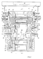
- FIG. 2 shows the preferred form of flow diverter and system in which the seal means of the invention is used.
- the diverter 22 is shown in place within a housing 24 which is mounted below the rig floor 44 in which the bore 46 of diverter 22 is in line with the bore of the rotary table 28.
- the width of the diverter 22 is advantageously designed so that it may be lowered through the rotary table into engagement with permanently affixed housing 24.
- Housing 24 is fixed with respect to the rig floor 44 by means of I beams 46 which are attached by support members 47 as frustrated.
- Diverter 22 comprises a generally cylindrical body 50 in which an annular packing element 52 is disposed in its upper part.
- the diverter includes a base 54 the upper part of which partially supports annular packing element 52.
- An annular space between the base 54 and the outer body 50 is provided to contain a first piston, outer valve sleeve 56, and a second piston, annular piston 58.
- Annular piston 58 is generally of the kind used in annular blowout preventers.
- the upper part 110 of piston 58 is in the shape of a conical bowl for engaging the packing element 52 in a conventional fashion.
- Head 60 forms the top part of the flow diverter and is connected to body 50 by means of studs 62.
- a spacer or wear ring 64 confines the packing element 52 within the flow diverter housing.
- the flow diverter fits within the bore of permanently mounted housing 24 and is attached by means of a latching mechanism thereto, such as multi-shouldered dogs 66 which engage complementary grooves in the diverter body 50.
- the dogs 66 are driven by a piston 68 and rod 70.
- a latch port 72 is provided for applying pressurized hydraulic fluid behind the piston 68 to drive dog 66 into engagement with the diverter body 50.
- An unlatch port 74 is provided for driving piston 68 away from the diverter body thereby unlatching the dogs 66.
- the area of the piston 68 on its latch side 69 is smaller than on its unlatch side 69' to facilitate unlatching even where the dogs have been jammed or stuck.
- Vent line means 80 and drilling fluid flow line means 82 are shown permanently attached to the housing 24, the attachment being, for example, by welds 83, but the flow line means may be attached advantageously by bolting or other attaching means.
- the vent line means 80 extends away from the drilling rig such that when the diverter opens the bore of the drilling conduit to the vent line. pressurized drilling fluid may be vented away from the drilling rig and, in the case of a drilling vessel, may be directed to the leeward side of the vessel.
- the flow line means 82 is preferably directed to the drilling fluid system of the drilling rig, most likely to the shale shaker, where drilling cuttings which have been washed by the drilling fluid are removed from the fluid and where the fluid may be reentered into the drilling system in conventional fashion.
- the first piston or valve sleeve 56 is provided with two passages or holes 84 and 86 provided in its wall.
- the annular piston 58 has two holes 88 and 90 provided in its wall as illustrated in Figure 2.
- holes 92 and 94 are provided in the wall of the base 54.
- holes 96 and 98 are provided in the body wall 50 of the diverter and, after insertion in housing 24, are in alignment with the vent line means 80 and the flow line means 82.
- Figure 2 illustrates the flow diverter in its normal state during which drilling operations are conducted through its bore and in which the return of the drilling fluid via the annulus is conducted.
- the bore of the diverter is provided for fluid communication with the bore of the drilling conduit attached beneath the diverter 22 as illustrated in Figure 1.
- Drilling fluid is returned to the drilling rig « mud - or fluid system via the hole 94 in the base, the hole 90 in the annular piston and thence through the hole 86 in the annular sleeve 56 and the hole 98 in the wall 50 of the body for fluid communication through the flow line means 82 to the drilling rig fluid system.
- the upper part 100 of the valve sleeve 56 covers the hole 96 provided in the body 50 such that no drilling fluid from the interior of the diverter is allowed to communicate with the vent line means 80.
- the annular packer 52 is in its normal relaxed position leaving an annular space between any pipe or object and the bore of the diverter and fluid communication exists between the bore of the diverter and the flow line means 82.
- Hydraulic fluid conduit 102 is connected to a source (not shown) of pressurized hydraulic control fluid via a port 104 for applying pressurized hydraulic fluid beneath valve sleeve piston 56 and annular piston 58.
- a port 104 for applying pressurized hydraulic fluid beneath valve sleeve piston 56 and annular piston 58.
- an operator may open port 104 to the source of pressurized hydraulic fluid wherein the pressurized fluid is applied to region 106 beneath the valve sleeve 56 and the annular piston 58.
- valve sleeve 56 is caused to move in an upward axial direction before the annular piston 58, because more area is provided underneath valve sleeve 56 than is provided under annular piston 58, because of the opposing effect of the annular packing element 52 on the conical bowl portion 110 of annular piston 58 and because it has less mass relative to annular piston 58 opposing the motion.
- hydraulic fluid under valve sleeve 56 and annular piston 58 drives valve sleeve 56 upward whereby the hole 86 in valve sleeve 56 is driven upwardly and out of alignment with the hole 98 in the body wall.
- hole 84 in the wall of valve sleeve 56 is driven upwardly and into alignment with hole 96 in the wall of the body 50.
- the annular piston 58 begins to move after the valve sleeve 56 and in so doing the upper conical bowl portion 110 of piston 58 forces the packing element 52 radially inwardly.
- the upper surface 111 of the sleeve 56 is adapted to engage with downward facing shoulder 112 on the conical bowl portion 110 of piston 58 providing additional upward force to piston 58 until valve sleeve reaches its maximum upward travel.
- Piston 58 continues to move upwardly until the annulus between a drill pipe or other object in the well bore and the bore 46 of the diverter 22 is closed off.
- Figure 3 illustrates the diverter after the annular piston 58 and the valve sleeve 56 have moved to their « actuated positions and have caused annular packing element 52 to close about pipe 112 in the bore of the diverter.
- Hole 84 of valve sleeve 56 has moved into alignment with hole 96 allowing fluid communication via hole 92 provided in the base of the diverter and the hole 88 provided in the annular piston 58 wall. Any pressurized drilling fluid in the bore of the diverter is safely diverted away from the drilling rig via vent line means 82.
- Hole 88 is sufficiently large that flow between the bore of the body via hole 92 is not prevented when piston 58 moves upwardly.
- valve sleeve 56 is shown in Figure 3 covering the hole 98 which is in alignment with the flow line means 82, thereby preventing further fluid communication between the bore of the diverter and the flow line means 82 to the drilling fluid system, Closing of the flow line means 82 thereby prevents the flow of possibly highly combustible, pressurized drilling fluid to the rig drilling fluid system.
- the fluid system may be in a confined part of the drilling vessel and could create an extremely hazardous condition if the flow of drilling fluid pressurized with gas from an underground formation is not terminated as quickly as possible.
- Figure 2 also shows a means by which the valve sleeve 56 is prevented from failing to close the flow line means 82 and to open the vent line means 80 during kick.
- a ring 114 provided in the lower part of the annular piston 58 is provided for engagement with an annular shoulder 116 of valve sleeve 56. If the valve sleeve 56 were to become stuck and fail to move upwardly on the application of hydraulic fluid beneath its area 106, the ring 114 of piston 58 on its upward movement would engage the shoulder 116, thereby forcing the valve sleeve 116 upwardly.
- the ring 114 would force sleeve 56 upward until hole 84 becomes aligned with hole 96 thereby opening the bore of the diverter to the vent line means 96 and simultaneously causing the lower part of the valve sleeve 56 to cover hole 98 in the bore of the diverter thereby preventing further fluid communication to the drilling rig fluid system.
- Hydraulic line 120 is provided via port 122 for connection to a source of pressurized hydraulic control fluid to an area 126 above a shoulder provided in the bottom of the valve sleeve 56.
- Hydraulic line 120 is provided via port 122 for connection to a source of pressurized hydraulic control fluid to an area 126 above a shoulder provided in the bottom of the valve sleeve 56.
- a plurality of sealing means are provided to contain either pressurized hydraulic fluid under the valve sleeve 56 and annular piston 58 or to seal about other openings and holes in the pistons and body walls.
- sealing means 121 and 122 prevent pressurized hydraulic fluid beneath valve sleeve 56 from escaping into the interior of the diverter.
- valve sealing means 124 and 126 seal against loss of hydraulic fluid beneath annular piston 58.
- Sealing means 130 and 132 provide sealing for the upper conical bowl section 110 of annular piston 58 as it moves upwardly for forcing annular packing element radially inward.
- integral seals 140 are provided on the wall 50 of the diverter 22 for sealing the wall 50 of the diverter against the wall of the permanent housing 24 and also for providing a seal with the valve sleeve 56 as it moves across the openings 96 and 98 in the wall of the body.
- a detailed description of a preferred embodiment of the seals 140 is presented below.
- FIG. 4 shows a portion of a cross-section through the line 4-4 shown in Figure 2, means are provided for aligning the diverter 22 within the permanently mounted housing 24.
- the diverter is adapted to be lowered by the drilling rig travelling block through the rotary table and into the bore of housing 24.
- Means are provided for aligning the diverter 22 both axially and- angularly such that the holes 96 and 98 are in alignment with the permanently mounted vent line means 80 and the flow line means 82 which are permanently attached to the housing 24.
- Axial alignment is achieved by providing an inwardly facing annular shoulder 150 in the permanent housing 24 and a complementary outwardly facing shoulder 151. Engagement of the complementary shoulders 150 and 151 causes the diverter to come to rest at the proper axial or vertical alignment within the housing 24.
- Angular alignment is accomplished by means of an alignment key 160 extending through the wall 50, the valve sleeve 56 and the annular piston 58 into engagement with base 54.
- the head 162 of the key 160 partially extends outwardly from the wall 50 for engagement into an axial slot 164 provided in a portion of the wall of housing 24.
- the key 160 serves to prevent angular rotation of valve sleeve 56 and annular piston 58 thereby insuring that the holes 84 and 86 of the valve sleeve 56 and the holes 88 and 90 of the annular piston 58 do not move out of angular alignment once the diverter is in place within the permanent housing 24.
- Slot 165 illustrated in Figure 4A is provided in the key 160 so that drilling fluid within the annular space extending between the holes 92 and 94 of the base 54 and holes 88 and 90 of the annular piston 58 is not impeded from moving up or down by the key itself, but rather may move freely through the key.
- the hydraulic fluid ports 104 and 122 are also aligned with openings 170 and 172 in the body 50 of the diverter 22 when the alignment key head 162 fits within alignment slot 164 of the permanent housing 24.
- Sealing means 180 and 182 provide a seal about the hydraulic fluid opening 170 while seal means 184 and 186 seal about the opening 172 with respect to the permanent housing 24 wall.
- the diverter 22 is easily aligned both axially and angularly such that passages in the body wall of the diverter are aligned with the vent line and flow line means and with the hydraulic ports for operating the diverter.
- FIG. 1 illustrates the position of key 160 as the valve sleeve 56 and annular piston 58 have been moved upwardly during an emergency situation.
- Illustrated in Figure 2 is an outwardly extending annular space 200 which is provided to accept a test tool, thereby simulating a test pipe or other object extending through the bore of the housing about which the annular packing unit 52 may be closed in order to test the operation of the diverter.
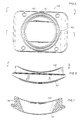
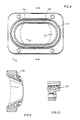
- Figures 5 through 10 illustrate the integral seal 140 of the invention provided in the wall 50 of the diverter 22.
- the seal is adapted to be affixed within the wall about the opening 96 or the opening 98 in the body wall.
- the holes 96 and 98 are oblong on the interior of the body wall while circular on the exterior of the wall.
- the purpose for providing such a passage through the body wall 50 is to minimize the height of the hole in the interior of the body wall 50 while maintaining a maximum area of the outlet passage so as not to hinder significantly the flow therethrough thereby preventing creation of potentially hazardous back pressure during emergency venting.
- vent line means 80 and the flow line means 82 normally are cylindrical tubular members having a circular opening, thereby requiring that the outlet on the exterior wall of the diverter be circular in shape.
- sealing member 140 is provided about the opening in the body wall which is advantageously provided to seal against the permanent housing on the exterior of the diverter wall and against the valve sleeve 56 movement on the interior of the diverter wall.
- the seal is embodied in a molded or cast member which may be easily manufactured obviating the necessity of machining two unusually shaped holes in each diverter housing which are costly and relatively difficult to machine.
- sealing member 140 is preferably an integral member of elastomeric material and preferably has a support member embedded therein to give it strength.
- sealing member 140 may be an integral member fabricated from non-elastomer materials. For example, it may be cast steel, ceramic or a composite material.
- Figure 5 illustrates the seal member as viewed from its exterior side showing the opening 141 on its outside being circular in nature and showing the interior oblong hole 142. Exterior sealing rings 143 are shown for sealing the permanent housing 24 against the exterior of the body diverter.
- Figure 8 shows the sealing element as viewed from the inside of the diverter showing the interior opening 142 being of oblong shape in which the height of the opening is less than its width.
- the exterior circular opening 141 is also illustrated.
- Interior sealing ridge 144 is provided for sealing against the valve sleeve 56 as it either comes into alignment with the opening 142 or seals the opening with an upper part of the sleeve where the vent line means is covered or the lower part of the piston 56 where the flow line means is covered.
- Sealing shoulder 145 is provided for sealing the seal assembly 140 to the housing wall 50.
- Figure 6 illustrates the shape of the seal element when viewed from its side in which the oblong opening 142 is shown as well as the circular opening 141.
- a metallic support member 190 is provided in the seal element 140 and extends completely about the warped surface defined by the member connecting the circular opening 141 with the oblong opening 142.
- Figures 9 and 10 illustrate in cross-section how the support element 190 is preferably disposed within the sealing element itself.
Landscapes
- Engineering & Computer Science (AREA)
- Life Sciences & Earth Sciences (AREA)
- Geology (AREA)
- Mining & Mineral Resources (AREA)
- Physics & Mathematics (AREA)
- Environmental & Geological Engineering (AREA)
- Fluid Mechanics (AREA)
- General Life Sciences & Earth Sciences (AREA)
- Geochemistry & Mineralogy (AREA)
- Mechanical Engineering (AREA)
- General Engineering & Computer Science (AREA)
- Earth Drilling (AREA)
Abstract
Description
- This invention relates generally to a diverter apparatus and system for redirecting the flow of drilling fluid or mud and cuttings that would otherwise be blown upward to the rig floor during a kick encountered during initial hole drilling and more specifically to a seal used in an apparatus and system adapted for use beneath the drilling floor of any land or marine drilling rig. In particular, the seal is used in an apparatus and system utilized with floating drilling equipment.
- When drilling an oil or gas well, an initial large diameter bore hole is established to shallow depths. Protective drive conduit or conductor pipe, typically 76,20 cm (30 inches) in diameter, is secured in the shallow bore through which the drilling takes place. For offshore drilling, a subsea riser extends from the sea floor to the marine drilling platform. Flow diverters are typically provided below the rig floor and between the conductor conduit and the rotary table of the drilling rig for the purpose of safely venting unbalanced well bore pressure which may produce an upward flow of drilling fluid in the conduit having sufficient impetus to issue from the top of the conduit thereby contributing a hazard to personnel and equipment. Such an occurrence, called a kick v, typically of formation gas accumulations in the fluid of the conduit is often encountered in top hole drilling making a flow diverter essential before blowout preventers are connected to the drilling system, especially for offshore applications. A flow diverter is considered necessary for safe operation on a floating offshore drilling rig where blowout preventers are placed on the sea floor only after the casing has been set to a depth, usuallyseveral hundred feet below the sea floor.
- Prior diverter systems have been primarily of two types. The first includes a flow diverter assembly requiring different diameter packing inserts to accommodate different diameter tubular members (see e. g. US-A-4 066 241). Such diverter systems are unable to accomplish complete shut off on open hole. The second has included an annular blowout preventer placed above the vent line in which a valve is disposed to an open condition only when the annular blowout preventer is closed about the drill pipe or other object in the well bore in response to a kick in the annulus of the bore hole.
- In the first type of flow diverters, packer elements must be changed for different size tubulars used during drilling and must be removed during tripping of the bottom hole assembly. Such a task is rigorous drudgery to the rig personnel. The well bore is in general left unprotected when there is no object in the well bore because the diverter is not able to close on open hole.
- In the second type of flow diverter system the combined height of the annular blowout preventer and of the side outlets of the vent line below the annular blowout preventer may require excessive head room under the rig floor.
- For both types of systems which have been provided in the past, a significant safety problem has arisen due to the requirement of opening an external valve in the vent line and closing the valve leading typically to the shale shaker of the drilling rig fluid system. In the past, such valves have often been closed by rig personnel while testing the flow diverter, but after the flow diverter has been made operational during drilling, the external valves inadvertently have been allowed to remain closed. On occasion, the control system elements have been inadvertently incorrectly connected resulting in simultaneous closure of all of the diverter system valves and the diverter itself. If the prior flow diverters have closed about the annulus of a drill pipe or other object in the well bore, such flow diverter systems have created an extremely dangerous situation, and in fact in some cases they have exploded with the result of loss of life and property.
- It is an object of the invention to provide sealing means for use in the housing of the flow diverter apparatus to seal about vent and flow lines permanently installed in a housing below the rig floor.
- The present invention therefore provides a seal for installation in the cylindrical outer wall of the housing of a flow diverter about an outlet passage through the housing wall, the outlet passage connecting an oblong hole in the interior of the wall with a substantially circular hole in the exterior of the wall, said seal including an integral member having an outer section adapted to conform generally with the curvature of the outside of the cylindrical housing wall and having a generally circular opening therein with at least one generally circular sealing shoulder disposed outwardly from the circular opening, an inner section adapted to conform generally with the curvature of the inside of the cylindrical housing wall and having an oblong opening therein with a first oblong sealing shoulder disposed outwardly from the oblong opening, a connecting section between the outer section and inner section having a bore therein connecting the circular hole with the oblong hole, and means for sealing the seal to the housing wall.
- Preferably the integral seal member according to the invention is provided about each of the outlet passages in the wall of the diverter, Further, the connecting section between the outer section and the inner section and preferably has an inward warped surface bore geometrically defined by the surface connecting the circular hole with the oblong hole.
- The seal is supported and stiffened preferably by means of an integral rigid support member embedded in the elastomeric material and having an outer section disposed about the outer opening, an inner section disposed about the warped surface geometrically defined by the bore connecting the circular hole with the oblong hole and an inner section disposed about the inner opening.
- Further features and advantages of the invention will become more apparent by reference to the following description of a preferred embodiment of the invention taken together with the accompanying drawings wherein :
- Figure 1 illustrates a drilling rig of a floating drill ship, barge or semi-submersible to which the flow diverting apparatus is attached beneath the rig floor and above drilling conduit extending to the subsea surface ;
- Figure 2 illustrates a preferred form of the flow diverting apparatus in place within a housing and connected to vent and flow lines where the housing and vent lines are fixed beneath a drilling rig floor ;
- Figure 3 illustrates the flow diverting apparatus in which an annular packing element has been closed about a pipe in the bore of the apparatus and in which a vent line has been opened and a flow line has been closed ;
- Figure 4 illustrates an alignment key by which the flow diverter may be inserted into a permanent housing and aligned angularly with respect to the permanent housing ;
- Figure 4A illustrates in more detail the alignment key shown in Figure 4 :
- Figures 5 through 10 illustrate in various views and cross-sections a preferred embodiment of the seal made in accordance with the invention and used to seal about an opening in the apparatus extending to either the vent line or flow line of the invention ;
- Figure 1 illustrates a
drilling rig 20 of a floating drill ship, barge orsemi-submersible 21. The flow diverter of the invention shown generally at 22 is provided below thedrilling rig 20 in a permanently installedhousing 24 which is mounted below the rotary table 28 of thedrilling rig 20. Thediverter 22 is connected to adrilling conduit 30, in this case a ball or flex joint for connecting to a riserinner barrel 32. Typically, in a drilling system of a floating vessel, atelescopic joint 34 allows for the heave, surge and sway of the vessel andriser joints 36 extend to the sea floor at which a wellhead member 38 is provided about 76,20 cm (30 inches) conduit 40 into the earth's surface. - It should be emphasized that while the prefered environment in which theflowdiverterand system are illustrated is with marine drilling from a floating vessel, the invention may also be used with a flow diverter and system for marine drilling from a bottom supported platform or for land drilling from a land based rig. Figure 1 also illustrates a vent line means 42 and a flow line means 43 which may be permanently provided and fixed to the
housing 24. The connection of the flow diverter 22 tohousing 24 and vent line and flow line means will be described in detail below. - Figure 2 shows the preferred form of flow diverter and system in which the seal means of the invention is used. The
diverter 22 is shown in place within ahousing 24 which is mounted below the rig floor 44 in which thebore 46 ofdiverter 22 is in line with the bore of the rotary table 28. The width of thediverter 22 is advantageously designed so that it may be lowered through the rotary table into engagement with permanently affixedhousing 24.Housing 24 is fixed with respect to the rig floor 44 by means of Ibeams 46 which are attached bysupport members 47 as frustrated. -
Diverter 22 comprises a generallycylindrical body 50 in which anannular packing element 52 is disposed in its upper part. The diverter includes abase 54 the upper part of which partially supportsannular packing element 52. An annular space between thebase 54 and theouter body 50 is provided to contain a first piston,outer valve sleeve 56, and a second piston,annular piston 58.Annular piston 58 is generally of the kind used in annular blowout preventers. Theupper part 110 ofpiston 58 is in the shape of a conical bowl for engaging thepacking element 52 in a conventional fashion.Head 60 forms the top part of the flow diverter and is connected tobody 50 by means ofstuds 62. A spacer orwear ring 64 confines thepacking element 52 within the flow diverter housing. - The flow diverter fits within the bore of permanently mounted
housing 24 and is attached by means of a latching mechanism thereto, such asmulti-shouldered dogs 66 which engage complementary grooves in thediverter body 50. Thedogs 66 are driven by apiston 68 androd 70. Alatch port 72 is provided for applying pressurized hydraulic fluid behind thepiston 68 to drivedog 66 into engagement with thediverter body 50. Anunlatch port 74 is provided for drivingpiston 68 away from the diverter body thereby unlatching thedogs 66. Advantageously, the area of thepiston 68 on itslatch side 69 is smaller than on its unlatch side 69' to facilitate unlatching even where the dogs have been jammed or stuck. - Flow line are permanently mounted with
housing 24 according to the invention. Vent line means 80 and drilling fluid flow line means 82 are shown permanently attached to thehousing 24, the attachment being, for example, bywelds 83, but the flow line means may be attached advantageously by bolting or other attaching means. The vent line means 80 extends away from the drilling rig such that when the diverter opens the bore of the drilling conduit to the vent line. pressurized drilling fluid may be vented away from the drilling rig and, in the case of a drilling vessel, may be directed to the leeward side of the vessel. The flow line means 82 is preferably directed to the drilling fluid system of the drilling rig, most likely to the shale shaker, where drilling cuttings which have been washed by the drilling fluid are removed from the fluid and where the fluid may be reentered into the drilling system in conventional fashion. - The first piston or
valve sleeve 56 is provided with two passages orholes annular piston 58 has twoholes holes base 54. Likewise,holes body wall 50 of the diverter and, after insertion inhousing 24, are in alignment with the vent line means 80 and the flow line means 82. - Figure 2 illustrates the flow diverter in its normal state during which drilling operations are conducted through its bore and in which the return of the drilling fluid via the annulus is conducted. The bore of the diverter is provided for fluid communication with the bore of the drilling conduit attached beneath the
diverter 22 as illustrated in Figure 1. Drilling fluid is returned to the drilling rig « mud - or fluid system via thehole 94 in the base, thehole 90 in the annular piston and thence through thehole 86 in theannular sleeve 56 and thehole 98 in thewall 50 of the body for fluid communication through the flow line means 82 to the drilling rig fluid system. - On the other hand, the
upper part 100 of thevalve sleeve 56 covers thehole 96 provided in thebody 50 such that no drilling fluid from the interior of the diverter is allowed to communicate with the vent line means 80. Thus, during normal drilling operations theannular packer 52 is in its normal relaxed position leaving an annular space between any pipe or object and the bore of the diverter and fluid communication exists between the bore of the diverter and the flow line means 82. - Hydraulic
fluid conduit 102 is connected to a source (not shown) of pressurized hydraulic control fluid via aport 104 for applying pressurized hydraulic fluid beneathvalve sleeve piston 56 andannular piston 58. During a kick -, an operator may openport 104 to the source of pressurized hydraulic fluid wherein the pressurized fluid is applied toregion 106 beneath thevalve sleeve 56 and theannular piston 58. - The
valve sleeve 56 is caused to move in an upward axial direction before theannular piston 58, because more area is provided underneathvalve sleeve 56 than is provided underannular piston 58, because of the opposing effect of theannular packing element 52 on theconical bowl portion 110 ofannular piston 58 and because it has less mass relative toannular piston 58 opposing the motion. During a kick, hydraulic fluid undervalve sleeve 56 andannular piston 58drives valve sleeve 56 upward whereby thehole 86 invalve sleeve 56 is driven upwardly and out of alignment with thehole 98 in the body wall. Simultaneously,hole 84 in the wall ofvalve sleeve 56 is driven upwardly and into alignment withhole 96 in the wall of thebody 50. - The
annular piston 58 begins to move after thevalve sleeve 56 and in so doing the upperconical bowl portion 110 ofpiston 58 forces the packingelement 52 radially inwardly. Asvalve sleeve 56 moves upwardly. theupper surface 111 of thesleeve 56 is adapted to engage with downward facingshoulder 112 on theconical bowl portion 110 ofpiston 58 providing additional upward force topiston 58 until valve sleeve reaches its maximum upward travel.Piston 58 continues to move upwardly until the annulus between a drill pipe or other object in the well bore and thebore 46 of thediverter 22 is closed off. - Figure 3 illustrates the diverter after the
annular piston 58 and thevalve sleeve 56 have moved to their « actuated positions and have causedannular packing element 52 to close aboutpipe 112 in the bore of the diverter.Hole 84 ofvalve sleeve 56 has moved into alignment withhole 96 allowing fluid communication viahole 92 provided in the base of the diverter and thehole 88 provided in theannular piston 58 wall. Any pressurized drilling fluid in the bore of the diverter is safely diverted away from the drilling rig via vent line means 82.Hole 88 is sufficiently large that flow between the bore of the body viahole 92 is not prevented whenpiston 58 moves upwardly. - The
lower part 114 ofvalve sleeve 56 is shown in Figure 3 covering thehole 98 which is in alignment with the flow line means 82, thereby preventing further fluid communication between the bore of the diverter and the flow line means 82 to the drilling fluid system, Closing of the flow line means 82 thereby prevents the flow of possibly highly combustible, pressurized drilling fluid to the rig drilling fluid system. For the case of a floating drilling rig, the fluid system may be in a confined part of the drilling vessel and could create an extremely hazardous condition if the flow of drilling fluid pressurized with gas from an underground formation is not terminated as quickly as possible. - Figure 2 also shows a means by which the
valve sleeve 56 is prevented from failing to close the flow line means 82 and to open the vent line means 80 during kick. Aring 114 provided in the lower part of theannular piston 58 is provided for engagement with anannular shoulder 116 ofvalve sleeve 56. If thevalve sleeve 56 were to become stuck and fail to move upwardly on the application of hydraulic fluid beneath itsarea 106, thering 114 ofpiston 58 on its upward movement would engage theshoulder 116, thereby forcing thevalve sleeve 116 upwardly. Thering 114 would forcesleeve 56 upward untilhole 84 becomes aligned withhole 96 thereby opening the bore of the diverter to the vent line means 96 and simultaneously causing the lower part of thevalve sleeve 56 to coverhole 98 in the bore of the diverter thereby preventing further fluid communication to the drilling rig fluid system. - Means are provided to return the flow diverter to its normal position after any emergency has been corrected.
Hydraulic line 120 is provided viaport 122 for connection to a source of pressurized hydraulic control fluid to anarea 126 above a shoulder provided in the bottom of thevalve sleeve 56. When hydraulic fluid viaport 104 is removed, application of pressurized hydraulic fluid viaport 122 drivesvalve sleeve 56 downwardly to its normal position.Shoulder 116 in engagement withring 114 forces annularpiston 58 downwardly to its rest or normal position. - A plurality of sealing means are provided to contain either pressurized hydraulic fluid under the
valve sleeve 56 andannular piston 58 or to seal about other openings and holes in the pistons and body walls. For example, sealing means 121 and 122 prevent pressurized hydraulic fluid beneathvalve sleeve 56 from escaping into the interior of the diverter. Likewise, valve sealing means 124 and 126 seal against loss of hydraulic fluid beneathannular piston 58. Sealing means 130 and 132 provide sealing for the upperconical bowl section 110 ofannular piston 58 as it moves upwardly for forcing annular packing element radially inward. - In accordance with the invention,
integral seals 140 are provided on thewall 50 of thediverter 22 for sealing thewall 50 of the diverter against the wall of thepermanent housing 24 and also for providing a seal with thevalve sleeve 56 as it moves across theopenings seals 140 is presented below. - Turning now to Figure 4 which shows a portion of a cross-section through the line 4-4 shown in Figure 2, means are provided for aligning the
diverter 22 within the permanently mountedhousing 24. As discussed earlier, the diverter is adapted to be lowered by the drilling rig travelling block through the rotary table and into the bore ofhousing 24. Means are provided for aligning thediverter 22 both axially and- angularly such that theholes housing 24. Axial alignment is achieved by providing an inwardly facingannular shoulder 150 in thepermanent housing 24 and a complementary outwardly facingshoulder 151. Engagement of thecomplementary shoulders housing 24. - Angular alignment is accomplished by means of an
alignment key 160 extending through thewall 50, thevalve sleeve 56 and theannular piston 58 into engagement withbase 54. Thehead 162 of the key 160 partially extends outwardly from thewall 50 for engagement into anaxial slot 164 provided in a portion of the wall ofhousing 24. The key 160 serves to prevent angular rotation ofvalve sleeve 56 andannular piston 58 thereby insuring that theholes valve sleeve 56 and theholes annular piston 58 do not move out of angular alignment once the diverter is in place within thepermanent housing 24. The outward extension of thehead 162 ofkey 160 fitting within theslot 164 insures that thediverter 22 is aligned angularly with respect tohousing 24 such that thehole 96 in the body wall is in alignment with the vent line means 80 and thehole 98 is in alignment with the flow line means 82.Slot 164 in the housing provides the means by which thehead extension 162 insures the angular alignment. - Slot 165 illustrated in Figure 4A is provided in the key 160 so that drilling fluid within the annular space extending between the
holes base 54 and holes 88 and 90 of theannular piston 58 is not impeded from moving up or down by the key itself, but rather may move freely through the key. As may best be seen again in Figures 2 and 3, thehydraulic fluid ports openings body 50 of thediverter 22 when the alignmentkey head 162 fits withinalignment slot 164 of thepermanent housing 24. Sealing means 180 and 182 provide a seal about thehydraulic fluid opening 170 while seal means 184 and 186 seal about theopening 172 with respect to thepermanent housing 24 wall. Thus, there is provided a means by which thediverter 22 is easily aligned both axially and angularly such that passages in the body wall of the diverter are aligned with the vent line and flow line means and with the hydraulic ports for operating the diverter. - Returning again to Figure 2, the position of
key 160 is seen when the diverter is in a normal, not actuated condition. Theslots 190 and 192 illustrate the slots in the first piston orvalve sleeve 56 and second piston orannular piston 58 which allow the sleeve and piston to move with respect to the fixedkey 160. Figure 3 illustrates the position ofkey 160 as thevalve sleeve 56 andannular piston 58 have been moved upwardly during an emergency situation. - Illustrated in Figure 2 is an outwardly extending
annular space 200 which is provided to accept a test tool, thereby simulating a test pipe or other object extending through the bore of the housing about which theannular packing unit 52 may be closed in order to test the operation of the diverter. - Figures 5 through 10 illustrate the
integral seal 140 of the invention provided in thewall 50 of thediverter 22. The seal is adapted to be affixed within the wall about theopening 96 or theopening 98 in the body wall. Advantageously, theholes body wall 50 is to minimize the height of the hole in the interior of thebody wall 50 while maintaining a maximum area of the outlet passage so as not to hinder significantly the flow therethrough thereby preventing creation of potentially hazardous back pressure during emergency venting. It is advantageous to provide according to the invention, an outlet passage of minimum height in the interior of the wall of the diverter so that less axial upward movement of thevalve sleeve 56 is required to either open or close the hole. On the other hand, the vent line means 80 and the flow line means 82 normally are cylindrical tubular members having a circular opening, thereby requiring that the outlet on the exterior wall of the diverter be circular in shape. - Thus, an
integral sealing member 140 is provided about the opening in the body wall which is advantageously provided to seal against the permanent housing on the exterior of the diverter wall and against thevalve sleeve 56 movement on the interior of the diverter wall. According to another feature of the invention, the seal is embodied in a molded or cast member which may be easily manufactured obviating the necessity of machining two unusually shaped holes in each diverter housing which are costly and relatively difficult to machine. Thus, sealingmember 140 is preferably an integral member of elastomeric material and preferably has a support member embedded therein to give it strength. Alternatively, sealingmember 140 may be an integral member fabricated from non-elastomer materials. For example, it may be cast steel, ceramic or a composite material. - Figure 5 illustrates the seal member as viewed from its exterior side showing the
opening 141 on its outside being circular in nature and showing the interioroblong hole 142. Exterior sealing rings 143 are shown for sealing thepermanent housing 24 against the exterior of the body diverter. - Figure 8 shows the sealing element as viewed from the inside of the diverter showing the
interior opening 142 being of oblong shape in which the height of the opening is less than its width. The exteriorcircular opening 141 is also illustrated.Interior sealing ridge 144 is provided for sealing against thevalve sleeve 56 as it either comes into alignment with theopening 142 or seals the opening with an upper part of the sleeve where the vent line means is covered or the lower part of thepiston 56 where the flow line means is covered. Sealingshoulder 145 is provided for sealing theseal assembly 140 to thehousing wall 50. - Figure 6 illustrates the shape of the seal element when viewed from its side in which the
oblong opening 142 is shown as well as thecircular opening 141. Advantageously, ametallic support member 190 is provided in theseal element 140 and extends completely about the warped surface defined by the member connecting thecircular opening 141 with theoblong opening 142. - Figures 9 and 10 illustrate in cross-section how the
support element 190 is preferably disposed within the sealing element itself.
Claims (9)
Priority Applications (1)
| Application Number | Priority Date | Filing Date | Title |
|---|---|---|---|
| AT84900427T ATE24573T1 (en) | 1982-12-13 | 1983-12-12 | GASKET FOR FLOW DIVERTER. |
Applications Claiming Priority (2)
| Application Number | Priority Date | Filing Date | Title |
|---|---|---|---|
| US06/449,377 US4444401A (en) | 1982-12-13 | 1982-12-13 | Flow diverter seal with respective oblong and circular openings |
| US449377 | 1999-11-24 |
Publications (2)
| Publication Number | Publication Date |
|---|---|
| EP0128216A1 EP0128216A1 (en) | 1984-12-19 |
| EP0128216B1 true EP0128216B1 (en) | 1986-12-30 |
Family
ID=23783933
Family Applications (1)
| Application Number | Title | Priority Date | Filing Date |
|---|---|---|---|
| EP84900427A Expired EP0128216B1 (en) | 1982-12-13 | 1983-12-12 | Flow diverter seal |
Country Status (6)
| Country | Link |
|---|---|
| US (1) | US4444401A (en) |
| EP (1) | EP0128216B1 (en) |
| CA (1) | CA1248564A (en) |
| DE (1) | DE3368718D1 (en) |
| GB (1) | GB2141494B (en) |
| WO (1) | WO1984002373A1 (en) |
Families Citing this family (55)
| Publication number | Priority date | Publication date | Assignee | Title |
|---|---|---|---|---|
| US4566494A (en) * | 1983-01-17 | 1986-01-28 | Hydril Company | Vent line system |
| US4828024A (en) * | 1984-01-10 | 1989-05-09 | Hydril Company | Diverter system and blowout preventer |
| US4832126A (en) * | 1984-01-10 | 1989-05-23 | Hydril Company | Diverter system and blowout preventer |
| US4546828A (en) * | 1984-01-10 | 1985-10-15 | Hydril Company | Diverter system and blowout preventer |
| US4646844A (en) * | 1984-12-24 | 1987-03-03 | Hydril Company | Diverter/bop system and method for a bottom supported offshore drilling rig |
| US5012854A (en) * | 1987-03-31 | 1991-05-07 | Baroid Technology, Inc. | Pressure release valve for a subsea blowout preventer |
| US5000719A (en) * | 1990-01-03 | 1991-03-19 | Reed Lehman T | Retrievable sealing plug and method of making same |
| US5647444A (en) * | 1992-09-18 | 1997-07-15 | Williams; John R. | Rotating blowout preventor |
| US5662181A (en) | 1992-09-30 | 1997-09-02 | Williams; John R. | Rotating blowout preventer |
| US5305839A (en) * | 1993-01-19 | 1994-04-26 | Masx Energy Services Group, Inc. | Turbine pump ring for drilling heads |
| US5660234A (en) * | 1996-02-01 | 1997-08-26 | Abb Vetco Gray Inc. | Shallow flow wellhead system |
| US6041865A (en) * | 1997-10-31 | 2000-03-28 | Exmar Offshore Company | Method and apparatus for moving a diverter |
| US6263982B1 (en) | 1998-03-02 | 2001-07-24 | Weatherford Holding U.S., Inc. | Method and system for return of drilling fluid from a sealed marine riser to a floating drilling rig while drilling |
| US6913092B2 (en) | 1998-03-02 | 2005-07-05 | Weatherford/Lamb, Inc. | Method and system for return of drilling fluid from a sealed marine riser to a floating drilling rig while drilling |
| US6138774A (en) | 1998-03-02 | 2000-10-31 | Weatherford Holding U.S., Inc. | Method and apparatus for drilling a borehole into a subsea abnormal pore pressure environment |
| US6112810A (en) * | 1998-10-31 | 2000-09-05 | Weatherford/Lamb, Inc. | Remotely controlled assembly for wellbore flow diverter |
| DE60031959T2 (en) | 1999-03-02 | 2007-09-20 | Weatherford/Lamb, Inc., Houston | ROTATING CONTROL HEAD USED IN THE RISER |
| US7159669B2 (en) | 1999-03-02 | 2007-01-09 | Weatherford/Lamb, Inc. | Internal riser rotating control head |
| US7487837B2 (en) * | 2004-11-23 | 2009-02-10 | Weatherford/Lamb, Inc. | Riser rotating control device |
| US7836946B2 (en) | 2002-10-31 | 2010-11-23 | Weatherford/Lamb, Inc. | Rotating control head radial seal protection and leak detection systems |
| US7237623B2 (en) * | 2003-09-19 | 2007-07-03 | Weatherford/Lamb, Inc. | Method for pressurized mud cap and reverse circulation drilling from a floating drilling rig using a sealed marine riser |
| US8826988B2 (en) | 2004-11-23 | 2014-09-09 | Weatherford/Lamb, Inc. | Latch position indicator system and method |
| US7926593B2 (en) | 2004-11-23 | 2011-04-19 | Weatherford/Lamb, Inc. | Rotating control device docking station |
| CA2549484C (en) * | 2005-06-06 | 2013-05-21 | Lance Larsen | Well cap method and apparatus |
| US7717170B2 (en) * | 2007-08-27 | 2010-05-18 | Williams John R | Stripper rubber pot mounting structure and well drilling equipment comprising same |
| US7766100B2 (en) * | 2007-08-27 | 2010-08-03 | Theresa J. Williams, legal representative | Tapered surface bearing assembly and well drilling equiment comprising same |
| US7559359B2 (en) * | 2007-08-27 | 2009-07-14 | Williams John R | Spring preloaded bearing assembly and well drilling equipment comprising same |
| US7762320B2 (en) | 2007-08-27 | 2010-07-27 | Williams John R | Heat exchanger system and method of use thereof and well drilling equipment comprising same |
| US7789172B2 (en) | 2007-08-27 | 2010-09-07 | Williams John R | Tapered bearing assembly cover plate and well drilling equipment comprising same |
| US7635034B2 (en) * | 2007-08-27 | 2009-12-22 | Theresa J. Williams, legal representative | Spring load seal assembly and well drilling equipment comprising same |
| US7717169B2 (en) * | 2007-08-27 | 2010-05-18 | Theresa J. Williams, legal representative | Bearing assembly system with integral lubricant distribution and well drilling equipment comprising same |
| US7798250B2 (en) * | 2007-08-27 | 2010-09-21 | Theresa J. Williams, legal representative | Bearing assembly inner barrel and well drilling equipment comprising same |
| US7726416B2 (en) * | 2007-08-27 | 2010-06-01 | Theresa J. Williams, legal representative | Bearing assembly retaining apparatus and well drilling equipment comprising same |
| GB2453125B (en) * | 2007-09-25 | 2012-02-08 | Statoilhydro Asa | Deadleg |
| US7997345B2 (en) * | 2007-10-19 | 2011-08-16 | Weatherford/Lamb, Inc. | Universal marine diverter converter |
| US8286734B2 (en) | 2007-10-23 | 2012-10-16 | Weatherford/Lamb, Inc. | Low profile rotating control device |
| US8844652B2 (en) | 2007-10-23 | 2014-09-30 | Weatherford/Lamb, Inc. | Interlocking low profile rotating control device |
| US7708089B2 (en) * | 2008-02-07 | 2010-05-04 | Theresa J. Williams, legal representative | Breech lock stripper rubber pot mounting structure and well drilling equipment comprising same |
| GB0804306D0 (en) | 2008-03-07 | 2008-04-16 | Petrowell Ltd | Device |
| US9359853B2 (en) | 2009-01-15 | 2016-06-07 | Weatherford Technology Holdings, Llc | Acoustically controlled subsea latching and sealing system and method for an oilfield device |
| US8322432B2 (en) | 2009-01-15 | 2012-12-04 | Weatherford/Lamb, Inc. | Subsea internal riser rotating control device system and method |
| US8347983B2 (en) | 2009-07-31 | 2013-01-08 | Weatherford/Lamb, Inc. | Drilling with a high pressure rotating control device |
| US8347982B2 (en) | 2010-04-16 | 2013-01-08 | Weatherford/Lamb, Inc. | System and method for managing heave pressure from a floating rig |
| US9175542B2 (en) | 2010-06-28 | 2015-11-03 | Weatherford/Lamb, Inc. | Lubricating seal for use with a tubular |
| US8448711B2 (en) | 2010-09-23 | 2013-05-28 | Charles J. Miller | Pressure balanced drilling system and method using the same |
| US9670755B1 (en) * | 2011-06-14 | 2017-06-06 | Trendsetter Engineering, Inc. | Pump module systems for preventing or reducing release of hydrocarbons from a subsea formation |
| US10294746B2 (en) * | 2013-03-15 | 2019-05-21 | Cameron International Corporation | Riser gas handling system |
| WO2014179538A1 (en) | 2013-05-03 | 2014-11-06 | Ameriforge Group Inc. | Large-width/diameter riser segment lowerable through a rotary of a drilling rig |
| US9970247B2 (en) | 2013-05-03 | 2018-05-15 | Ameriforge Group Inc. | MPD-capable flow spools |
| US10082211B2 (en) * | 2016-07-13 | 2018-09-25 | Baker Hughes, A Ge Company, Llc | Inverted element valve |
| US10655403B2 (en) | 2017-04-06 | 2020-05-19 | Ameriforge Group Inc. | Splittable riser component |
| EP3607170B1 (en) * | 2017-04-06 | 2021-12-01 | Ameriforge Group Inc. | Integral dsit&flow spool |
| WO2020197822A1 (en) * | 2019-03-26 | 2020-10-01 | Worldwide Oilfield Machine, Inc. | Annular preventer |
| WO2021236574A1 (en) * | 2020-05-18 | 2021-11-25 | Lord Corporation | Split diverter seal |
| CN116513543B (en) * | 2023-06-21 | 2023-11-07 | 四川省欧邦动物药业有限公司 | Dust-proof packaging device for medicine powder and control method thereof |
Family Cites Families (15)
| Publication number | Priority date | Publication date | Assignee | Title |
|---|---|---|---|---|
| GB135811A (en) * | 1919-08-16 | 1919-12-04 | David Alexander Brown | Improvements in Stuffing Boxes. |
| US1467877A (en) * | 1921-10-10 | 1923-09-11 | Albert L Rea | Automatic stuffing box |
| FR650054A (en) * | 1928-02-07 | 1929-01-04 | Gasket for high pressure pots or ovens | |
| US2021104A (en) * | 1933-08-26 | 1935-11-12 | Leland P Kinnear | Blow-out preventer |
| US2484622A (en) * | 1945-11-01 | 1949-10-11 | Taylor Instr Company | Flow diversion valve |
| GB1191766A (en) * | 1968-10-28 | 1970-05-13 | Da Pro Rubber Inc | Sealing Gasket |
| US3587734A (en) * | 1969-09-08 | 1971-06-28 | Shafco Ind Inc | Adapter for converting a stationary blowout preventer to a rotary blowout preventer |
| US3741295A (en) * | 1970-07-31 | 1973-06-26 | Hydril Co | Replacement of sub sea blow out preventer packing units |
| US3926256A (en) * | 1973-07-30 | 1975-12-16 | Texaco Inc | Methods and apparatuses for controlling and preventing blow-outs in wells |
| US3917008A (en) * | 1974-10-29 | 1975-11-04 | Cities Service Co | Apparatus and process for preventing blow-outs |
| US4066241A (en) * | 1975-02-07 | 1978-01-03 | Dresser Industries, Inc. | Seal means for valve assembly |
| US4063602A (en) * | 1975-08-13 | 1977-12-20 | Exxon Production Research Company | Drilling fluid diverter system |
| JPS5244685A (en) * | 1975-10-06 | 1977-04-07 | Sumitomo Metal Ind Ltd | Packing for hydraulic testing device for steel pipes |
| US4321975A (en) * | 1980-06-02 | 1982-03-30 | Dyer Ronald S | Slurry diverter |
| US4378849A (en) * | 1981-02-27 | 1983-04-05 | Wilks Joe A | Blowout preventer with mechanically operated relief valve |
-
1982
- 1982-12-13 US US06/449,377 patent/US4444401A/en not_active Expired - Lifetime
-
1983
- 1983-12-12 WO PCT/US1983/001935 patent/WO1984002373A1/en not_active Ceased
- 1983-12-12 EP EP84900427A patent/EP0128216B1/en not_active Expired
- 1983-12-12 GB GB08420408A patent/GB2141494B/en not_active Expired
- 1983-12-12 DE DE8484900427T patent/DE3368718D1/en not_active Expired
- 1983-12-13 CA CA000443130A patent/CA1248564A/en not_active Expired
Also Published As
| Publication number | Publication date |
|---|---|
| WO1984002373A1 (en) | 1984-06-21 |
| CA1248564A (en) | 1989-01-10 |
| GB8420408D0 (en) | 1984-09-12 |
| EP0128216A1 (en) | 1984-12-19 |
| DE3368718D1 (en) | 1987-02-05 |
| GB2141494B (en) | 1986-12-31 |
| GB2141494A (en) | 1984-12-19 |
| US4444401A (en) | 1984-04-24 |
Similar Documents
| Publication | Publication Date | Title |
|---|---|---|
| US4444401A (en) | Flow diverter seal with respective oblong and circular openings | |
| US4502534A (en) | Flow diverter | |
| US4456063A (en) | Flow diverter | |
| US4456062A (en) | Flow diverter | |
| US4444250A (en) | Flow diverter | |
| US4832126A (en) | Diverter system and blowout preventer | |
| US4828024A (en) | Diverter system and blowout preventer | |
| US4546828A (en) | Diverter system and blowout preventer | |
| US4646844A (en) | Diverter/bop system and method for a bottom supported offshore drilling rig | |
| US6244359B1 (en) | Subsea diverter and rotating drilling head | |
| EP0198853B1 (en) | Marine riser well control method and apparatus | |
| US6109352A (en) | Simplified Xmas tree using sub-sea test tree | |
| CA1216515A (en) | Diverter/bop system and method for a bottom supported offshore drilling rig | |
| AU708871B2 (en) | Completion sub-sea test tree | |
| US4566494A (en) | Vent line system | |
| US4630680A (en) | Well control method and apparatus | |
| US20140238686A1 (en) | Internal riser rotating flow control device | |
| EP0943781B1 (en) | Sub-sea test tree | |
| GB2410517A (en) | Controlling production from a subsea oil or gas well | |
| GB2267920A (en) | Improvements in or relating to well-head structures | |
| AU2008234631A1 (en) | Rotating control device docking station | |
| US5769162A (en) | Dual bore annulus access valve | |
| AU2013204381A1 (en) | Improved Valve Apparatus | |
| EP0128206B1 (en) | Flow diverter | |
| US12560047B2 (en) | Riserless marine package |
Legal Events
| Date | Code | Title | Description |
|---|---|---|---|
| PUAI | Public reference made under article 153(3) epc to a published international application that has entered the european phase |
Free format text: ORIGINAL CODE: 0009012 |
|
| AK | Designated contracting states |
Designated state(s): AT BE CH DE FR GB LI LU NL SE |
|
| 17P | Request for examination filed |
Effective date: 19841119 |
|
| 17Q | First examination report despatched |
Effective date: 19860220 |
|
| GRAA | (expected) grant |
Free format text: ORIGINAL CODE: 0009210 |
|
| AK | Designated contracting states |
Kind code of ref document: B1 Designated state(s): AT BE CH DE FR GB LI LU NL SE |
|
| REF | Corresponds to: |
Ref document number: 24573 Country of ref document: AT Date of ref document: 19870115 Kind code of ref document: T |
|
| REF | Corresponds to: |
Ref document number: 3368718 Country of ref document: DE Date of ref document: 19870205 |
|
| ET | Fr: translation filed | ||
| PLBE | No opposition filed within time limit |
Free format text: ORIGINAL CODE: 0009261 |
|
| STAA | Information on the status of an ep patent application or granted ep patent |
Free format text: STATUS: NO OPPOSITION FILED WITHIN TIME LIMIT |
|
| PG25 | Lapsed in a contracting state [announced via postgrant information from national office to epo] |
Ref country code: AT Effective date: 19871212 |
|
| PG25 | Lapsed in a contracting state [announced via postgrant information from national office to epo] |
Ref country code: SE Effective date: 19871213 |
|
| 26N | No opposition filed | ||
| PG25 | Lapsed in a contracting state [announced via postgrant information from national office to epo] |
Ref country code: LU Free format text: LAPSE BECAUSE OF NON-PAYMENT OF DUE FEES Effective date: 19871231 Ref country code: LI Effective date: 19871231 Ref country code: CH Effective date: 19871231 Ref country code: BE Effective date: 19871231 |
|
| PGFP | Annual fee paid to national office [announced via postgrant information from national office to epo] |
Ref country code: NL Payment date: 19871231 Year of fee payment: 5 |
|
| BERE | Be: lapsed |
Owner name: HYDRIL CY Effective date: 19871231 |
|
| REG | Reference to a national code |
Ref country code: CH Ref legal event code: PL |
|
| PG25 | Lapsed in a contracting state [announced via postgrant information from national office to epo] |
Ref country code: NL Effective date: 19890701 |
|
| NLV4 | Nl: lapsed or anulled due to non-payment of the annual fee | ||
| EUG | Se: european patent has lapsed |
Ref document number: 84900427.0 Effective date: 19880913 |
|
| REG | Reference to a national code |
Ref country code: GB Ref legal event code: IF02 |
|
| PGFP | Annual fee paid to national office [announced via postgrant information from national office to epo] |
Ref country code: FR Payment date: 20020103 Year of fee payment: 19 Ref country code: DE Payment date: 20020103 Year of fee payment: 19 |
|
| PGFP | Annual fee paid to national office [announced via postgrant information from national office to epo] |
Ref country code: GB Payment date: 20020104 Year of fee payment: 19 |
|
| PG25 | Lapsed in a contracting state [announced via postgrant information from national office to epo] |
Ref country code: GB Free format text: LAPSE BECAUSE OF NON-PAYMENT OF DUE FEES Effective date: 20021212 |
|
| PG25 | Lapsed in a contracting state [announced via postgrant information from national office to epo] |
Ref country code: DE Free format text: LAPSE BECAUSE OF NON-PAYMENT OF DUE FEES Effective date: 20030701 |
|
| GBPC | Gb: european patent ceased through non-payment of renewal fee | ||
| PG25 | Lapsed in a contracting state [announced via postgrant information from national office to epo] |
Ref country code: FR Free format text: LAPSE BECAUSE OF NON-PAYMENT OF DUE FEES Effective date: 20030901 |
|
| REG | Reference to a national code |
Ref country code: FR Ref legal event code: ST |