EP0125672B1 - Basket of plastic material for the processing of the plates for dry-charge batteries - Google Patents
Basket of plastic material for the processing of the plates for dry-charge batteries Download PDFInfo
- Publication number
- EP0125672B1 EP0125672B1 EP84105417A EP84105417A EP0125672B1 EP 0125672 B1 EP0125672 B1 EP 0125672B1 EP 84105417 A EP84105417 A EP 84105417A EP 84105417 A EP84105417 A EP 84105417A EP 0125672 B1 EP0125672 B1 EP 0125672B1
- Authority
- EP
- European Patent Office
- Prior art keywords
- plates
- basket
- plate
- plastic material
- members
- Prior art date
- Legal status (The legal status is an assumption and is not a legal conclusion. Google has not performed a legal analysis and makes no representation as to the accuracy of the status listed.)
- Expired
Links
- 239000000463 material Substances 0.000 title claims abstract description 5
- 238000012545 processing Methods 0.000 title abstract description 4
- 230000000295 complement effect Effects 0.000 claims 2
- 210000002816 gill Anatomy 0.000 abstract 1
- 238000000465 moulding Methods 0.000 description 3
- 230000015572 biosynthetic process Effects 0.000 description 2
- 239000003792 electrolyte Substances 0.000 description 2
- 238000005755 formation reaction Methods 0.000 description 2
- 230000000903 blocking effect Effects 0.000 description 1
- 238000010276 construction Methods 0.000 description 1
- 230000008878 coupling Effects 0.000 description 1
- 238000010168 coupling process Methods 0.000 description 1
- 238000005859 coupling reaction Methods 0.000 description 1
- 230000000694 effects Effects 0.000 description 1
- 238000010325 electrochemical charging Methods 0.000 description 1
- 238000007654 immersion Methods 0.000 description 1
- 238000012994 industrial processing Methods 0.000 description 1
- 238000003780 insertion Methods 0.000 description 1
- 230000037431 insertion Effects 0.000 description 1
- 239000007788 liquid Substances 0.000 description 1
- 238000000034 method Methods 0.000 description 1
- 210000000056 organ Anatomy 0.000 description 1
- 238000007747 plating Methods 0.000 description 1
- 125000006850 spacer group Chemical group 0.000 description 1
Images

Classifications
-
- H—ELECTRICITY
- H01—ELECTRIC ELEMENTS
- H01M—PROCESSES OR MEANS, e.g. BATTERIES, FOR THE DIRECT CONVERSION OF CHEMICAL ENERGY INTO ELECTRICAL ENERGY
- H01M4/00—Electrodes
- H01M4/02—Electrodes composed of, or comprising, active material
- H01M4/14—Electrodes for lead-acid accumulators
- H01M4/16—Processes of manufacture
- H01M4/22—Forming of electrodes
-
- H—ELECTRICITY
- H01—ELECTRIC ELEMENTS
- H01M—PROCESSES OR MEANS, e.g. BATTERIES, FOR THE DIRECT CONVERSION OF CHEMICAL ENERGY INTO ELECTRICAL ENERGY
- H01M4/00—Electrodes
- H01M4/02—Electrodes composed of, or comprising, active material
- H01M4/04—Processes of manufacture in general
- H01M4/0438—Processes of manufacture in general by electrochemical processing
- H01M4/044—Activating, forming or electrochemical attack of the supporting material
-
- Y—GENERAL TAGGING OF NEW TECHNOLOGICAL DEVELOPMENTS; GENERAL TAGGING OF CROSS-SECTIONAL TECHNOLOGIES SPANNING OVER SEVERAL SECTIONS OF THE IPC; TECHNICAL SUBJECTS COVERED BY FORMER USPC CROSS-REFERENCE ART COLLECTIONS [XRACs] AND DIGESTS
- Y02—TECHNOLOGIES OR APPLICATIONS FOR MITIGATION OR ADAPTATION AGAINST CLIMATE CHANGE
- Y02E—REDUCTION OF GREENHOUSE GAS [GHG] EMISSIONS, RELATED TO ENERGY GENERATION, TRANSMISSION OR DISTRIBUTION
- Y02E60/00—Enabling technologies; Technologies with a potential or indirect contribution to GHG emissions mitigation
- Y02E60/10—Energy storage using batteries
Definitions
- the invention concerns a basket of plastic material especially suited for the processing of the plates for dry-charge batteries, including two equal plates in a comb shape with vertical slots, joined with each other by means of screws and adjustable in different positions.
- the plates which form the elements of industrial batteries undergo an electro-chemical charging treatment in plating vats, where the plates are made electrically active by means of the passage of electric power, which is brought about by the presence of an electrolyte liquid.
- the industrial processing foresees the immersion in the electrolyte of a certain number of plates assembled in suitable plastic baskets, suitably spaced the one from the other and with the surface to be treated as free as possible, so as to avoid a shielding which would prevent the treatment of the covered areas.
- the known baskets generally consist of four vertical, stiff walls being perpendicular to one another, where two opposite walls present some vertical and parallel comb-shaped slots into which the plates are inserted, while the other two walls only function as spacers and as connecting elements between one comb-shaped wall and the next.
- the present invention has been developed with the purpose of eliminating the need for a basket which foresees the use of intermediate diaphragms for the processing of plates having a width which is smaller than the maximum width of the basket.
- a basket consisting of two equal plates having a predominantly flat surface and supporting multiple parallel slots, each plate having four profiled members which are perpendicular to the main surface and are arranged at its corners and which are bound to one another by a screw-and-slot type of junction.
- the basket can house plates for batteries of any width comprised between the minimum and the maximum opening of the basket, even those having non unified dimensions, since the locking between the corresponding segments which are joined together, can be made by positioning the screws at any intermediate point inside the slot being present in one of the two segments which fit into each other.
- One more advantage derives from the fact that the treatment of plates of batteries having reduced widths reduce the overall dimensions of the basket and, as a consequence, a larger number of plates can be treated at the same time, since it is possible to dip a larger number of baskets in the treatment vat.
- two equal plates 10 and 20 moulding in plastic material, are the elements which, when joined together, form the basket.
- Each of said plates presents a flat and smooth surface on one side, while on the other side a series of vertical ribs 2 are obtained by moulding; said ribs being spaced the one from the other by the thickness of the plates which are inserted between then.
- Four profiled members 3, 4, 5, and 6 being perpendicular to the vertical surface are present.
- the profiled members 4 and 5 have a perfectly identical shape. Each of them has a slotted guide 7 in which the slot 8 is obtained; profiled member 5 belonging to element 10 matches profiled member 3 of the opposite plate 20 which is placed in the front. In particular the shaped profile 3a of projection 3 of plate 20 enters into the slotted guide 7 of segment 5. In the same way the slotted guide 7 belonging to segment 4 of plate 10, also having a slot 8 matches the corresponding shaped profile 6a of segment 6 belonging to element 20, which is placed in front of it.
- Fig. 3 shows the connection between profiled member 3 of plate 20 and the profiled member 5 of plate 10.
- the shaped profile 3a of profiled member 3 is provided with three passing holes 11, 12 and 13 which flare out on the external part. Two of these holes, for instance 11 and 12, receive two screws of type 14 which pass through slot 8 and are then screwed into the threaded holes 15 and 16 of block 17.
- Both the block 17 and the shaped profile 7 of profiled member 5 are provided with indented formations, marked with 18 for block 17 and with 19 for the shaped profile 7, which prevent the mutual sliding between the profiled members 3 and 5. If there were not indented formation sliding would be possible should the screws not be tightened enough or because of the thermic changes which the basket is subject to when it is dipped in the electrolytic bath.
- the plates in dry-charge batteries inserted into the slots of the basket thus formed rest their lower side on a straight bar 21, which is present in each of the plate 10 and 20.
- This bar is arranged in a position which is parallel to the gilled surfaces of each element and it is connected to it by means of the protruding ribs 22.
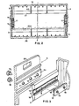
- Fig. 2 represents in cross-section the basket formed by the plates 10 and 20 joined with each other.
- the portion 20a represented by a broken line shows the basket in its most closed position.
- profiled member 3 although it has the same slotted shaped profile as profiled member 6 and although it is also provided with 3 holes for the receiving of the locking screws, presents, unlike profiled member 6, an opening 23 which is meant for the insertion of one of the hooks for the lifting and the transportation of the baskets.
Landscapes
- Engineering & Computer Science (AREA)
- Manufacturing & Machinery (AREA)
- Chemical & Material Sciences (AREA)
- Chemical Kinetics & Catalysis (AREA)
- Electrochemistry (AREA)
- General Chemical & Material Sciences (AREA)
- Laminated Bodies (AREA)
- Sealing Battery Cases Or Jackets (AREA)
- Centrifugal Separators (AREA)
- Battery Mounting, Suspending (AREA)
Abstract
Description
- The invention concerns a basket of plastic material especially suited for the processing of the plates for dry-charge batteries, including two equal plates in a comb shape with vertical slots, joined with each other by means of screws and adjustable in different positions.
- The plates which form the elements of industrial batteries undergo an electro-chemical charging treatment in plating vats, where the plates are made electrically active by means of the passage of electric power, which is brought about by the presence of an electrolyte liquid. The industrial processing foresees the immersion in the electrolyte of a certain number of plates assembled in suitable plastic baskets, suitably spaced the one from the other and with the surface to be treated as free as possible, so as to avoid a shielding which would prevent the treatment of the covered areas.
- The known baskets generally consist of four vertical, stiff walls being perpendicular to one another, where two opposite walls present some vertical and parallel comb-shaped slots into which the plates are inserted, while the other two walls only function as spacers and as connecting elements between one comb-shaped wall and the next.
- Since there are plates with unified dimensions, which, however, are varied both in height and in width, the known baskets foresee one or more vertical slots in the lateral connecting walls, into which another comb-shaped plastic plate is inserted when plates having a width smaller than the maximum one are to be treated.
- The present invention has been developed with the purpose of eliminating the need for a basket which foresees the use of intermediate diaphragms for the processing of plates having a width which is smaller than the maximum width of the basket.
- The purpose is achieved by means of a basket, consisting of two equal plates having a predominantly flat surface and supporting multiple parallel slots, each plate having four profiled members which are perpendicular to the main surface and are arranged at its corners and which are bound to one another by a screw-and-slot type of junction.
- An adjustable container is described in the USA
patent 3 463 343, in which the basket is formed by two adjustable telescopic container sections, but the sections are different and two different dies are needed to make this basket by a moulding process. - One of the advantages obtained with the present invention is that the basket can house plates for batteries of any width comprised between the minimum and the maximum opening of the basket, even those having non unified dimensions, since the locking between the corresponding segments which are joined together, can be made by positioning the screws at any intermediate point inside the slot being present in one of the two segments which fit into each other. One more advantage derives from the fact that the treatment of plates of batteries having reduced widths reduce the overall dimensions of the basket and, as a consequence, a larger number of plates can be treated at the same time, since it is possible to dip a larger number of baskets in the treatment vat.
- Another advantage of the present construction arises from the fact that these baskets, when not used, occupy a reduced total space, since it is possible to position them so, that the two elements which form them are as near as possible to each other.
- Other details and other functional advantages will be better pointed out in the description of a preferred form of execution, which is given by way of example only, but is not meant to be limiting, illustrated in the enclosed drawings, where:
- Fig. 1 represents in perspective view the two equal plates which, when joined together, form the adjustable basket
- Fig. 2 is a cross-section of the already formed basket with the joining details being emphasized.
- Fig. 3 shows in perspective view the special form of two profiled member which are joined together and the organ connecting them.
- With reference to fig. 1, two
equal plates members - The profiled
members 4 and 5 have a perfectly identical shape. Each of them has aslotted guide 7 in which theslot 8 is obtained; profiledmember 5 belonging toelement 10 matches profiledmember 3 of theopposite plate 20 which is placed in the front. In particular the shaped profile 3a ofprojection 3 ofplate 20 enters into theslotted guide 7 ofsegment 5. In the same way theslotted guide 7 belonging to segment 4 ofplate 10, also having aslot 8 matches the corresponding shaped profile 6a ofsegment 6 belonging toelement 20, which is placed in front of it. - The locking between the profiled
members members 4 and 6 in a certain position is obtained, for each coupling, by means of an indented block. Fig. 3 shows the connection between profiledmember 3 ofplate 20 and the profiledmember 5 ofplate 10. The shaped profile 3a of profiledmember 3 is provided with threepassing holes instance type 14 which pass throughslot 8 and are then screwed into the threadedholes block 17. Both theblock 17 and theshaped profile 7 of profiledmember 5 are provided with indented formations, marked with 18 forblock 17 and with 19 for theshaped profile 7, which prevent the mutual sliding between the profiledmembers - Even though a single screw would be mechanically sufficient to insure the junction between the two profiled
members member 5 could bend, thereby determining the blocking of or the impossibility of inserting the plate to be treated in the position which is closest to this profiled member. Therefore, in the case of maximum opening of the basket, thescrews 14 are inserted into thepassing holes holes slot 8 which is present in the profiledmembers 4 and 5. - The plates in dry-charge batteries inserted into the slots of the basket thus formed rest their lower side on a
straight bar 21, which is present in each of theplate protruding ribs 22. - Fig. 2 represents in cross-section the basket formed by the
plates - Finally it is pointed out that profiled
member 3, although it has the same slotted shaped profile as profiledmember 6 and although it is also provided with 3 holes for the receiving of the locking screws, presents, unlike profiledmember 6, anopening 23 which is meant for the insertion of one of the hooks for the lifting and the transportation of the baskets.
Claims (2)
Priority Applications (1)
| Application Number | Priority Date | Filing Date | Title |
|---|---|---|---|
| AT84105417T ATE36921T1 (en) | 1983-05-17 | 1984-05-12 | PLASTIC BASKET FOR HANDLING DRY BATTERY PLATES. |
Applications Claiming Priority (2)
| Application Number | Priority Date | Filing Date | Title |
|---|---|---|---|
| IT6428783U | 1983-05-17 | ||
| IT8364287U IT8364287V0 (en) | 1983-05-17 | 1983-05-17 | PLASTIC BASKET FOR THE FORMATION OF PLATES FOR DRY-CHARGED ACCUMULATORS. |
Publications (3)
| Publication Number | Publication Date |
|---|---|
| EP0125672A2 EP0125672A2 (en) | 1984-11-21 |
| EP0125672A3 EP0125672A3 (en) | 1986-03-12 |
| EP0125672B1 true EP0125672B1 (en) | 1988-08-31 |
Family
ID=11295996
Family Applications (1)
| Application Number | Title | Priority Date | Filing Date |
|---|---|---|---|
| EP84105417A Expired EP0125672B1 (en) | 1983-05-17 | 1984-05-12 | Basket of plastic material for the processing of the plates for dry-charge batteries |
Country Status (4)
| Country | Link |
|---|---|
| EP (1) | EP0125672B1 (en) |
| AT (1) | ATE36921T1 (en) |
| DE (1) | DE3473802D1 (en) |
| IT (1) | IT8364287V0 (en) |
Family Cites Families (5)
| Publication number | Priority date | Publication date | Assignee | Title |
|---|---|---|---|---|
| DE167693C (en) * | ||||
| US1633354A (en) * | 1926-01-28 | 1927-06-21 | Edward F Rau | Collapsible and adjustable crate for furniture |
| US2767951A (en) * | 1953-11-06 | 1956-10-23 | Ex Corp | Shelf lock |
| GB1135733A (en) * | 1966-01-24 | 1968-12-04 | Caoutchouc S A Soc Ind Du | Insert for forming vessels for accumulator plates |
| US3463343A (en) * | 1967-08-28 | 1969-08-26 | Shell Oil Co | Adjustable circuit board box |
-
1983
- 1983-05-17 IT IT8364287U patent/IT8364287V0/en unknown
-
1984
- 1984-05-12 DE DE8484105417T patent/DE3473802D1/en not_active Expired
- 1984-05-12 AT AT84105417T patent/ATE36921T1/en not_active IP Right Cessation
- 1984-05-12 EP EP84105417A patent/EP0125672B1/en not_active Expired
Also Published As
| Publication number | Publication date |
|---|---|
| EP0125672A2 (en) | 1984-11-21 |
| EP0125672A3 (en) | 1986-03-12 |
| ATE36921T1 (en) | 1988-09-15 |
| DE3473802D1 (en) | 1988-10-06 |
| IT8364287V0 (en) | 1983-05-17 |
Similar Documents
| Publication | Publication Date | Title |
|---|---|---|
| US5441337A (en) | Component cabinet | |
| EP0056898B1 (en) | Stackable flat cable clamp | |
| US4116510A (en) | Chassis formed of sheet stock | |
| US5333950A (en) | Control cabinet with rack and mounting plate | |
| EP0230083A1 (en) | System for constructing air conditioning cabinets and method for constructing same | |
| RU177194U1 (en) | SWITCHING UNIT AND SWITCHING PANEL | |
| ES296010U (en) | Rack. | |
| US4113926A (en) | Cell racks | |
| GB897951A (en) | Supporting trough | |
| GB2282527A (en) | Mounting frame for electrical equipment | |
| EP0125672B1 (en) | Basket of plastic material for the processing of the plates for dry-charge batteries | |
| US4018982A (en) | Housing structure for electrical apparatus | |
| EP2693513A1 (en) | A container for plates of a battery | |
| KR100576951B1 (en) | Combination steel frame consisting of profile members connected by screws | |
| US3677929A (en) | Adjustable frame for thin sheet electrodes | |
| EP0161226A2 (en) | Installation duct and mounting bracket therefor | |
| PL194923B1 (en) | Upright member of an electric distribution cabinet supporting metal frame | |
| CN219226969U (en) | Wire arranging device and cabinet with same | |
| DE3137131A1 (en) | BUILT-IN HOUSING | |
| CN207705264U (en) | A kind of battery modules copper bar side shell component | |
| US3110538A (en) | Mounting means for an electrical connector | |
| EP0155545A2 (en) | A drawer for electrical cabinets | |
| US3923161A (en) | System of structural components for the construction of shelflike structures in frame racks | |
| CN209709621U (en) | A kind of plastic wire groove | |
| GB2035703A (en) | Rack for accommodating circuit boards |
Legal Events
| Date | Code | Title | Description |
|---|---|---|---|
| PUAI | Public reference made under article 153(3) epc to a published international application that has entered the european phase |
Free format text: ORIGINAL CODE: 0009012 |
|
| AK | Designated contracting states |
Designated state(s): AT BE CH DE FR GB LI NL SE |
|
| PUAL | Search report despatched |
Free format text: ORIGINAL CODE: 0009013 |
|
| AK | Designated contracting states |
Kind code of ref document: A3 Designated state(s): AT BE CH DE FR GB LI NL SE |
|
| 17P | Request for examination filed |
Effective date: 19860520 |
|
| 17Q | First examination report despatched |
Effective date: 19870119 |
|
| GRAA | (expected) grant |
Free format text: ORIGINAL CODE: 0009210 |
|
| AK | Designated contracting states |
Kind code of ref document: B1 Designated state(s): AT BE CH DE FR GB LI NL SE |
|
| REF | Corresponds to: |
Ref document number: 36921 Country of ref document: AT Date of ref document: 19880915 Kind code of ref document: T |
|
| REF | Corresponds to: |
Ref document number: 3473802 Country of ref document: DE Date of ref document: 19881006 |
|
| ET | Fr: translation filed | ||
| PLBE | No opposition filed within time limit |
Free format text: ORIGINAL CODE: 0009261 |
|
| STAA | Information on the status of an ep patent application or granted ep patent |
Free format text: STATUS: NO OPPOSITION FILED WITHIN TIME LIMIT |
|
| 26N | No opposition filed | ||
| EAL | Se: european patent in force in sweden |
Ref document number: 84105417.4 |
|
| PGFP | Annual fee paid to national office [announced via postgrant information from national office to epo] |
Ref country code: SE Payment date: 19990429 Year of fee payment: 16 |
|
| PG25 | Lapsed in a contracting state [announced via postgrant information from national office to epo] |
Ref country code: SE Free format text: LAPSE BECAUSE OF NON-PAYMENT OF DUE FEES Effective date: 20000513 |
|
| PGFP | Annual fee paid to national office [announced via postgrant information from national office to epo] |
Ref country code: BE Payment date: 20000523 Year of fee payment: 17 Ref country code: AT Payment date: 20000523 Year of fee payment: 17 |
|
| PGFP | Annual fee paid to national office [announced via postgrant information from national office to epo] |
Ref country code: NL Payment date: 20000531 Year of fee payment: 17 |
|
| PGFP | Annual fee paid to national office [announced via postgrant information from national office to epo] |
Ref country code: DE Payment date: 20000727 Year of fee payment: 17 |
|
| PGFP | Annual fee paid to national office [announced via postgrant information from national office to epo] |
Ref country code: CH Payment date: 20000809 Year of fee payment: 17 |
|
| EUG | Se: european patent has lapsed |
Ref document number: 84105417.4 |
|
| PGFP | Annual fee paid to national office [announced via postgrant information from national office to epo] |
Ref country code: GB Payment date: 20010509 Year of fee payment: 18 |
|
| PG25 | Lapsed in a contracting state [announced via postgrant information from national office to epo] |
Ref country code: AT Free format text: LAPSE BECAUSE OF NON-PAYMENT OF DUE FEES Effective date: 20010512 |
|
| PGFP | Annual fee paid to national office [announced via postgrant information from national office to epo] |
Ref country code: FR Payment date: 20010518 Year of fee payment: 18 |
|
| PG25 | Lapsed in a contracting state [announced via postgrant information from national office to epo] |
Ref country code: BE Free format text: LAPSE BECAUSE OF NON-PAYMENT OF DUE FEES Effective date: 20010531 |
|
| PG25 | Lapsed in a contracting state [announced via postgrant information from national office to epo] |
Ref country code: LI Free format text: LAPSE BECAUSE OF NON-PAYMENT OF DUE FEES Effective date: 20010611 Ref country code: CH Free format text: LAPSE BECAUSE OF NON-PAYMENT OF DUE FEES Effective date: 20010611 |
|
| BERE | Be: lapsed |
Owner name: STOCCHIERO OLIMPIO Effective date: 20010531 |
|
| PG25 | Lapsed in a contracting state [announced via postgrant information from national office to epo] |
Ref country code: NL Free format text: LAPSE BECAUSE OF NON-PAYMENT OF DUE FEES Effective date: 20011201 |
|
| REG | Reference to a national code |
Ref country code: GB Ref legal event code: IF02 |
|
| REG | Reference to a national code |
Ref country code: CH Ref legal event code: PL |
|
| NLV4 | Nl: lapsed or anulled due to non-payment of the annual fee |
Effective date: 20011201 |
|
| PG25 | Lapsed in a contracting state [announced via postgrant information from national office to epo] |
Ref country code: DE Free format text: LAPSE BECAUSE OF NON-PAYMENT OF DUE FEES Effective date: 20020301 |
|
| PG25 | Lapsed in a contracting state [announced via postgrant information from national office to epo] |
Ref country code: GB Free format text: LAPSE BECAUSE OF NON-PAYMENT OF DUE FEES Effective date: 20020512 |
|
| GBPC | Gb: european patent ceased through non-payment of renewal fee |
Effective date: 20020512 |
|
| PG25 | Lapsed in a contracting state [announced via postgrant information from national office to epo] |
Ref country code: FR Free format text: LAPSE BECAUSE OF NON-PAYMENT OF DUE FEES Effective date: 20030131 |
|
| REG | Reference to a national code |
Ref country code: FR Ref legal event code: ST |