EP0125538B1 - Single acting fluid-pressure-operable device - Google Patents
Single acting fluid-pressure-operable device Download PDFInfo
- Publication number
- EP0125538B1 EP0125538B1 EP19840104634 EP84104634A EP0125538B1 EP 0125538 B1 EP0125538 B1 EP 0125538B1 EP 19840104634 EP19840104634 EP 19840104634 EP 84104634 A EP84104634 A EP 84104634A EP 0125538 B1 EP0125538 B1 EP 0125538B1
- Authority
- EP
- European Patent Office
- Prior art keywords
- pressure
- chamber
- components
- sealing element
- working chamber
- Prior art date
- Legal status (The legal status is an assumption and is not a legal conclusion. Google has not performed a legal analysis and makes no representation as to the accuracy of the status listed.)
- Expired
Links
- 238000007789 sealing Methods 0.000 claims abstract description 30
- 239000012530 fluid Substances 0.000 claims abstract description 6
- 239000000463 material Substances 0.000 claims abstract description 6
- 239000013536 elastomeric material Substances 0.000 claims abstract description 4
- 230000002093 peripheral effect Effects 0.000 claims description 7
- 230000006378 damage Effects 0.000 description 2
- 208000027418 Wounds and injury Diseases 0.000 description 1
- 230000000694 effects Effects 0.000 description 1
- 208000014674 injury Diseases 0.000 description 1
- 239000007788 liquid Substances 0.000 description 1
- 239000004033 plastic Substances 0.000 description 1
- 229920003023 plastic Polymers 0.000 description 1
- 230000002459 sustained effect Effects 0.000 description 1
- 230000003313 weakening effect Effects 0.000 description 1
Images
Classifications
-
- F—MECHANICAL ENGINEERING; LIGHTING; HEATING; WEAPONS; BLASTING
- F16—ENGINEERING ELEMENTS AND UNITS; GENERAL MEASURES FOR PRODUCING AND MAINTAINING EFFECTIVE FUNCTIONING OF MACHINES OR INSTALLATIONS; THERMAL INSULATION IN GENERAL
- F16J—PISTONS; CYLINDERS; SEALINGS
- F16J13/00—Covers or similar closure members for pressure vessels in general
-
- F—MECHANICAL ENGINEERING; LIGHTING; HEATING; WEAPONS; BLASTING
- F16—ENGINEERING ELEMENTS AND UNITS; GENERAL MEASURES FOR PRODUCING AND MAINTAINING EFFECTIVE FUNCTIONING OF MACHINES OR INSTALLATIONS; THERMAL INSULATION IN GENERAL
- F16K—VALVES; TAPS; COCKS; ACTUATING-FLOATS; DEVICES FOR VENTING OR AERATING
- F16K15/00—Check valves
- F16K15/14—Check valves with flexible valve members
- F16K15/148—Check valves with flexible valve members the closure elements being fixed in their centre
-
- A—HUMAN NECESSITIES
- A63—SPORTS; GAMES; AMUSEMENTS
- A63H—TOYS, e.g. TOPS, DOLLS, HOOPS OR BUILDING BLOCKS
- A63H33/00—Other toys
- A63H33/04—Building blocks, strips, or similar building parts
- A63H33/042—Mechanical, electrical, optical, pneumatic or hydraulic arrangements; Motors
-
- F—MECHANICAL ENGINEERING; LIGHTING; HEATING; WEAPONS; BLASTING
- F15—FLUID-PRESSURE ACTUATORS; HYDRAULICS OR PNEUMATICS IN GENERAL
- F15B—SYSTEMS ACTING BY MEANS OF FLUIDS IN GENERAL; FLUID-PRESSURE ACTUATORS, e.g. SERVOMOTORS; DETAILS OF FLUID-PRESSURE SYSTEMS, NOT OTHERWISE PROVIDED FOR
- F15B15/00—Fluid-actuated devices for displacing a member from one position to another; Gearing associated therewith
- F15B15/08—Characterised by the construction of the motor unit
- F15B15/14—Characterised by the construction of the motor unit of the straight-cylinder type
- F15B15/1423—Component parts; Constructional details
- F15B15/1447—Pistons; Piston to piston rod assemblies
- F15B15/1452—Piston sealings
-
- F—MECHANICAL ENGINEERING; LIGHTING; HEATING; WEAPONS; BLASTING
- F16—ENGINEERING ELEMENTS AND UNITS; GENERAL MEASURES FOR PRODUCING AND MAINTAINING EFFECTIVE FUNCTIONING OF MACHINES OR INSTALLATIONS; THERMAL INSULATION IN GENERAL
- F16J—PISTONS; CYLINDERS; SEALINGS
- F16J15/00—Sealings
- F16J15/16—Sealings between relatively-moving surfaces
- F16J15/164—Sealings between relatively-moving surfaces the sealing action depending on movements; pressure difference, temperature or presence of leaking fluid
-
- Y—GENERAL TAGGING OF NEW TECHNOLOGICAL DEVELOPMENTS; GENERAL TAGGING OF CROSS-SECTIONAL TECHNOLOGIES SPANNING OVER SEVERAL SECTIONS OF THE IPC; TECHNICAL SUBJECTS COVERED BY FORMER USPC CROSS-REFERENCE ART COLLECTIONS [XRACs] AND DIGESTS
- Y10—TECHNICAL SUBJECTS COVERED BY FORMER USPC
- Y10S—TECHNICAL SUBJECTS COVERED BY FORMER USPC CROSS-REFERENCE ART COLLECTIONS [XRACs] AND DIGESTS
- Y10S277/00—Seal for a joint or juncture
- Y10S277/928—Seal including pressure relief or vent feature
-
- Y—GENERAL TAGGING OF NEW TECHNOLOGICAL DEVELOPMENTS; GENERAL TAGGING OF CROSS-SECTIONAL TECHNOLOGIES SPANNING OVER SEVERAL SECTIONS OF THE IPC; TECHNICAL SUBJECTS COVERED BY FORMER USPC CROSS-REFERENCE ART COLLECTIONS [XRACs] AND DIGESTS
- Y10—TECHNICAL SUBJECTS COVERED BY FORMER USPC
- Y10T—TECHNICAL SUBJECTS COVERED BY FORMER US CLASSIFICATION
- Y10T137/00—Fluid handling
- Y10T137/7722—Line condition change responsive valves
- Y10T137/7837—Direct response valves [i.e., check valve type]
- Y10T137/7879—Resilient material valve
- Y10T137/7888—With valve member flexing about securement
- Y10T137/789—Central mount
Definitions
- This invention relates to a single acting fluid-pressure-operable device in accordance with the introductory part of the claim.
- a pressure relief valve set at an appropriate value has been provided, for example fitted in a wall of the working chamber.
- the relief valve has automatically opened to relieve the condition and to avoid any damage being sustained by the device.
- sealing means suitably engaged with, and disposed between, the relatively-movable components of the device have maintained their sealing effects despite the build-up in pressure in the working chamber.
- the invention as claimed is intended to provide a remedy. It solves this problem by providing a single acting fluid-pressure-operable device in which the means for pressure relief is combined with the sealing means engaged with two relatively-movable components of the device.
- a single acting fluid-pressure-operable device which includes two relatively-movable components defining a variable-volume working chamber subjectable to fluid under pressure, is provided with a sealing element of elastomeric material which is carried, or formed, by one of said components and which is in sliding and sealing engagement with the other of said components normally to resist escape of fluid under pressure from said working chamber to the exterior thereof, is characterised in that the peripheral edge portion of said sealing element has a convex cross-section and in that the face of said sealing element remote from said working chamber is so provided with a channel of U-shaped cross section that as the pressure in said chamber increases the sealing element is permitted progressively to deform and some of the material of the element thus displaced being then accommodated by the channel, whereby when said pressure exceeds a predetermined value the deformation of said sealing element is such that said sealing engagement of said element with said other of said components is broken so that the pressure in said working chamber is relieved to the exterior thereof.
- the fluid-pressure-operable device is of piston-and-cylinder type and the sealing element is suitably mounted upon the piston thereof and normally having peripheral line contact with the wall of the cylinder.
- the sealing element is permitted progressively to deform and some of the material of the element thus displaced is accommodated by the channel or the like whereby said pressure can be relieved past said element.
- the advantages offered by the invention are mainly that by so designing the sealing element to both perform a sealing function and permit relief of excess pressure in said working chamber, a relatively compact fluid-pressure-operable device is provided.
- the fluid-pressure-operable device 1 shown in the drawings is a jack of piston-and-cylinder type, the cylinder 2, the piston 3 and the piston rod 4 of which are of suitable plastics material.
- An elastomeric sealing element 5 of rubber or rubber-like material is carried upon the piston 3 in the manner shown.
- the peripheral edge portion 6 of element 5 is normally in line engagement at 7 with the inner wall 8 of cylinder 2.
- the device 1 is of single-acting type, compressed air being admitted to the working chamber 9 of cylinder 2 through a port 10 immediately adjacent the cylinder end wall 11.
- the other end wall 12 of the cylinder has ports 13 which place the annular chamber 14 to the left of piston 3 in communication with atmosphere.
- element 5 is provided with a channel in the form of an annular groove 16 of U-shaped cross-section. This groove effectively weakens the structure of the left-hand portion of the element 5 for the purpose now to be described.
- the element 5 no longer acts to seal but instead acts as a relief valve to ensure that no dangerous pressure condition prevails in chamber 9 which might cause failure of cylinder 2 and possible injury to users of the device.
- the device 1 is operable by compressed air
- the device is instead operable under liquid pressure.
Landscapes
- Engineering & Computer Science (AREA)
- General Engineering & Computer Science (AREA)
- Mechanical Engineering (AREA)
- Physics & Mathematics (AREA)
- Fluid Mechanics (AREA)
- Actuator (AREA)
- Sealing Devices (AREA)
- Measuring Pulse, Heart Rate, Blood Pressure Or Blood Flow (AREA)
- Pistons, Piston Rings, And Cylinders (AREA)
- Braking Systems And Boosters (AREA)
- Safety Valves (AREA)
- Control Of Fluid Pressure (AREA)
- Forklifts And Lifting Vehicles (AREA)
- Steering Control In Accordance With Driving Conditions (AREA)
Abstract
Description
- This invention relates to a single acting fluid-pressure-operable device in accordance with the introductory part of the claim.
- Hitherto in certain fluid-pressure-operable devices, where it has been particularly vital for reasons of safety that the build-up of fluid pressure in a working chamber of the device should not exceed a predetermined value, a pressure relief valve set at an appropriate value has been provided, for example fitted in a wall of the working chamber. Thus, when the predetermined pressure in that chamber is exceeded the relief valve has automatically opened to relieve the condition and to avoid any damage being sustained by the device. At the same time sealing means suitably engaged with, and disposed between, the relatively-movable components of the device have maintained their sealing effects despite the build-up in pressure in the working chamber.
- In fluid-pressure-operable devices, for example of piston-and-cylinder type, of relatively small size and for use at relatively low working pressures the provision of a pressure relief valve so fitted in a wall of the device has proved to be somewhat unwieldy and in consequence the device has lacked desired compactness. Further, the provision of the relief valve has added substantially to the cost of the device.
- The invention as claimed is intended to provide a remedy. It solves this problem by providing a single acting fluid-pressure-operable device in which the means for pressure relief is combined with the sealing means engaged with two relatively-movable components of the device.
- According to this invention a single acting fluid-pressure-operable device, which includes two relatively-movable components defining a variable-volume working chamber subjectable to fluid under pressure, is provided with a sealing element of elastomeric material which is carried, or formed, by one of said components and which is in sliding and sealing engagement with the other of said components normally to resist escape of fluid under pressure from said working chamber to the exterior thereof, is characterised in that the peripheral edge portion of said sealing element has a convex cross-section and in that the face of said sealing element remote from said working chamber is so provided with a channel of U-shaped cross section that as the pressure in said chamber increases the sealing element is permitted progressively to deform and some of the material of the element thus displaced being then accommodated by the channel, whereby when said pressure exceeds a predetermined value the deformation of said sealing element is such that said sealing engagement of said element with said other of said components is broken so that the pressure in said working chamber is relieved to the exterior thereof.
- The fluid-pressure-operable device is of piston-and-cylinder type and the sealing element is suitably mounted upon the piston thereof and normally having peripheral line contact with the wall of the cylinder.
- The sealing element is permitted progressively to deform and some of the material of the element thus displaced is accommodated by the channel or the like whereby said pressure can be relieved past said element.
- The advantages offered by the invention are mainly that by so designing the sealing element to both perform a sealing function and permit relief of excess pressure in said working chamber, a relatively compact fluid-pressure-operable device is provided.
- The invention is described below with reference to drawings which illustrate only one specific embodiment, in which:-
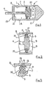
- Figure 1 is a cross-sectional side elevation of a fluid-pressure-operable device in accordance with the invention,
- Figure 2 is an enlarged cross-sectional view of the sealing element shown in Figure 1 during normal sealing operation, and
- Figure 3 is an enlargement of part of Figure 2 and shows the sealing element permitting pressure relief from within the fluid-pressure-operable device.
- The fluid-pressure-operable device 1 shown in the drawings is a jack of piston-and-cylinder type, the
cylinder 2, thepiston 3 and thepiston rod 4 of which are of suitable plastics material. - An
elastomeric sealing element 5 of rubber or rubber-like material is carried upon thepiston 3 in the manner shown. Theperipheral edge portion 6 ofelement 5 is normally in line engagement at 7 with the inner wall 8 ofcylinder 2. - The device 1 is of single-acting type, compressed air being admitted to the working chamber 9 of
cylinder 2 through aport 10 immediately adjacent thecylinder end wall 11. Theother end wall 12 of the cylinder hasports 13 which place theannular chamber 14 to the left ofpiston 3 in communication with atmosphere. - As shown more clearly in Figure 3 in its left-hand,
unpressurised face 15,element 5 is provided with a channel in the form of anannular groove 16 of U-shaped cross-section. This groove effectively weakens the structure of the left-hand portion of theelement 5 for the purpose now to be described. - In operation of the piston-and-cylinder device 1 when compressed air is admitted to the working chamber 9, the weakening of
element 5 produced bygroove 16 permits the element progressively to deform under the pressure applied to inclinedperipheral surface 17 as indicated by thearrows 18 in Figure 3. In consequence some of the elastomeric material ofperipheral edge portion 6 which is normally disposed adjacent thegroove 16 is therefore displaced into, thus being accommodated by, the groove. - When the pressure in chamber 9 reaches a predetermined value, for example in this
embodiment 1,5 bar, the deformation of theperipheral edge portion 6 reaches the condition shown in Figure 3, in which the sealing engagement at 7 ofelement 5 with the wall 8 of thecylinder 2 is broken. Hence the pressure in the chamber 9 is relieved past the sealingelement 5 to thechamber 14, as indicated by thearrow 19, and throughports 13 to atmosphere. - Thus, when the pressure in chamber 9 exceeds the predetermined value the
element 5 no longer acts to seal but instead acts as a relief valve to ensure that no dangerous pressure condition prevails in chamber 9 which might cause failure ofcylinder 2 and possible injury to users of the device. - When the pressure in chamber 9 falls back below the predetermined pressure the deformation of the
element 5 becomes less and the line engagement of the element with wall 8 is restored whereupon device 1 can recommence to operate normally. - Further, although in the embodiment above described with reference to the drawings the device 1 is operable by compressed air, in alternative embodiments of the invention the device is instead operable under liquid pressure.
Claims (1)
- A single acting fluid-pressure-operable device (1) including two relatively-movable components (2, 3) defining a variable-volume working chamber (9) subjectable to fluid under pressure, said device (1) being provided with an annular sealing element (5) of elastomeric material which is carried, or formed, by one of said components (3) and which is in sliding and sealing engagement with the other of said components (2) normally to resist escape of fluid under pressure from said working chamber (9) to the exterior thereof, characterized in that the peripheral edge portion (6) of said sealing element (5) has a convex cross-section, and in that the face (15) of said sealing element (5) remote from said working chamber (9) is so provided with a channel (16) of U-shaped cross section that as the pressure in said chamber increases the sealing element (5) is permitted progressively to deform and some of the material of the element thus displaced being then accommodated by the channel (16), whereby when said pressure exceeds a predetermined value the deformation of said sealing element (5) is such that said sealing engagement of said element (5) with said other of said components (2) is broken so that the pressure in said working chamber (9) is relieved to the exterior thereof.
Priority Applications (1)
| Application Number | Priority Date | Filing Date | Title |
|---|---|---|---|
| AT84104634T ATE28922T1 (en) | 1983-05-04 | 1984-04-25 | SINGLE-ACTING, PRESSURE OPERATED DEVICE. |
Applications Claiming Priority (2)
| Application Number | Priority Date | Filing Date | Title |
|---|---|---|---|
| GB8312166 | 1983-05-04 | ||
| GB8312166A GB2139318B (en) | 1983-05-04 | 1983-05-04 | Piston/cylinder seal construction |
Publications (2)
| Publication Number | Publication Date |
|---|---|
| EP0125538A1 EP0125538A1 (en) | 1984-11-21 |
| EP0125538B1 true EP0125538B1 (en) | 1987-08-12 |
Family
ID=10542122
Family Applications (1)
| Application Number | Title | Priority Date | Filing Date |
|---|---|---|---|
| EP19840104634 Expired EP0125538B1 (en) | 1983-05-04 | 1984-04-25 | Single acting fluid-pressure-operable device |
Country Status (9)
| Country | Link |
|---|---|
| US (1) | US4579041A (en) |
| EP (1) | EP0125538B1 (en) |
| JP (1) | JPS6018607A (en) |
| KR (1) | KR850000622A (en) |
| AT (1) | ATE28922T1 (en) |
| DE (1) | DE3465368D1 (en) |
| DK (1) | DK155135C (en) |
| ES (1) | ES287368Y (en) |
| GB (1) | GB2139318B (en) |
Families Citing this family (28)
| Publication number | Priority date | Publication date | Assignee | Title |
|---|---|---|---|---|
| FR2577199A1 (en) * | 1985-02-12 | 1986-08-14 | Gieza Paul | Method for packaging a bulk product in flexible packing |
| DE3538978C1 (en) * | 1985-11-02 | 1987-04-02 | Krupp Mak Maschb Gmbh | Piston-ring arrangement for trunk pistons |
| US4889351A (en) * | 1988-05-12 | 1989-12-26 | Frost Stanley A | Hydraulic seal |
| GB2231104B (en) * | 1989-03-11 | 1993-08-25 | Dowty Seals Ltd | Seal for a hydraulic ram |
| DE4016748A1 (en) * | 1990-05-25 | 1991-12-19 | Teves Gmbh Alfred | Pressure controller for vehicular antilock and antislip braking - includes construction in line from master cylinder to wheel brake cylinder with pressure limited by valve |
| US5100157A (en) * | 1990-10-01 | 1992-03-31 | S&C Electric Company | Sealing arrangement with overpressure relief |
| JP2598210B2 (en) * | 1992-12-01 | 1997-04-09 | エスエムシー株式会社 | Cylinder device |
| JP2766615B2 (en) * | 1993-10-18 | 1998-06-18 | エスエムシー株式会社 | Cylinder device |
| US5779108A (en) * | 1995-06-15 | 1998-07-14 | Calmar Inc. | Pressure venting trigger sprayer |
| NL1002292C2 (en) * | 1996-02-09 | 1997-08-12 | Applied Power Inc | Hydraulic ram with pressure-limitation |
| KR19980073002A (en) * | 1997-03-10 | 1998-11-05 | 구자홍 | Mold for optical glass molding |
| US5947787A (en) * | 1997-09-24 | 1999-09-07 | Parvia Corporation | Modular lattice substructure for a toy building set |
| US5924905A (en) * | 1997-09-24 | 1999-07-20 | Parvia Corporation | Modular terrain for a toy building set |
| US6129605A (en) * | 1997-09-24 | 2000-10-10 | Parvia Corporation | Modular base units for a toy building set |
| US5951356A (en) * | 1997-10-27 | 1999-09-14 | Parvia Corporation | Modular lattice substructure for a toy building set having columns and foundations |
| US5993283A (en) * | 1997-09-30 | 1999-11-30 | Parvia Corporation | Modular buildings for a toy building set |
| US6102770A (en) * | 1997-10-03 | 2000-08-15 | Parvia Corporation | Toy vehicular electromechanical guidance apparatus |
| US6007401A (en) * | 1997-10-03 | 1999-12-28 | Parvia Corporation | Optoelectric remote control apparatus for guiding toy vehicles |
| US5865661A (en) * | 1997-10-03 | 1999-02-02 | Parvia Corporation | Toy vehicular drive apparatus |
| US6012957A (en) * | 1997-10-27 | 2000-01-11 | Parvia Corporation | Single beam optoelectric remote control apparatus for control of toys |
| RU2262022C1 (en) * | 2004-02-11 | 2005-10-10 | Пинус Иосиф Яковлевич | Sealing unit for cylinder pairs of hydraulic and pneumatic machines |
| JP4589686B2 (en) * | 2004-09-28 | 2010-12-01 | 興国インテック株式会社 | Double adsorption gasket |
| FR2920493A1 (en) * | 2007-08-27 | 2009-03-06 | Asco Joucomatic Sa Sa | Single-acting jack e.g. single acting linear displacement hydraulic jack, for e.g. bottle filling machine, has rod, whose output and reentry phases are controlled by external mechanical solicitation, imposed force and imposed displacement |
| WO2012082018A1 (en) * | 2010-12-14 | 2012-06-21 | Volvo Lastavagnar Ab | A hydraulic device, a vehicle comprising such a hydraulic device and the use of such a hydraulic device for tilting of a cab arranged on a chassis |
| GB2513317B (en) * | 2013-04-22 | 2020-11-04 | Actuant Operations Uk Ltd | Failsafe mechanism |
| DE102016223758A1 (en) * | 2016-11-30 | 2018-05-30 | Robert Bosch Gmbh | Master brake cylinder, brake system |
| CN110375067B (en) * | 2019-06-25 | 2024-06-14 | 北京北分瑞利分析仪器(集团)有限责任公司 | Piston sealing structure applied to injector |
| CN113400889B (en) * | 2021-06-29 | 2023-01-24 | 镇江海姆霍兹传热传动系统有限公司 | Electric vehicle and its electric heater, electric cavity and pressure balance structure |
Family Cites Families (11)
| Publication number | Priority date | Publication date | Assignee | Title |
|---|---|---|---|---|
| US2444569A (en) * | 1943-03-11 | 1948-07-06 | Katcher Morris | Packing cup for master pistons |
| NL6508994A (en) * | 1965-07-13 | 1967-01-16 | ||
| US3391646A (en) * | 1967-09-28 | 1968-07-09 | Paul W. Schlosser | Piston assembly for pump |
| US3505815A (en) * | 1968-02-15 | 1970-04-14 | Toledo Stamping & Mfg Co | Trailer hitch with trailer brake actuator |
| DE7012963U (en) * | 1970-04-09 | 1970-07-30 | J P Sauer & Sohn Maschb Gmbh | DEVICE TO AVOID INADMISSIBLE PRESSURE DIFFERENCES IN PRESSURE MEDIUM CYLINDERS. |
| FR2246204A5 (en) * | 1973-09-28 | 1975-04-25 | Secmafer Sa | |
| GB1467640A (en) * | 1973-11-07 | 1977-03-16 | Girling Ltd | Piston and seal assemblies |
| JPS598036Y2 (en) * | 1977-08-20 | 1984-03-12 | トキコ株式会社 | cylinder device |
| US4116452A (en) * | 1977-11-07 | 1978-09-26 | Itt Industries, Inc. | Sleeve seal for master cylinders of hydraulic brake systems |
| US4262759A (en) * | 1979-09-24 | 1981-04-21 | Dresser Industries, Inc. | Combination seal and pressure relief valve for sealed drill string unit |
| DE3219134A1 (en) * | 1982-05-21 | 1983-11-24 | Teves Gmbh Alfred | MAIN CYLINDER FOR HYDRAULICALLY ACTUATED MOTOR VEHICLE BRAKES |
-
1983
- 1983-05-04 GB GB8312166A patent/GB2139318B/en not_active Expired
-
1984
- 1984-04-19 US US06/601,867 patent/US4579041A/en not_active Expired - Fee Related
- 1984-04-25 AT AT84104634T patent/ATE28922T1/en not_active IP Right Cessation
- 1984-04-25 EP EP19840104634 patent/EP0125538B1/en not_active Expired
- 1984-04-25 DE DE8484104634T patent/DE3465368D1/en not_active Expired
- 1984-04-27 KR KR1019840002255A patent/KR850000622A/en not_active Ceased
- 1984-05-02 JP JP59087941A patent/JPS6018607A/en active Pending
- 1984-05-02 ES ES1984287368U patent/ES287368Y/en not_active Expired
- 1984-05-03 DK DK219784A patent/DK155135C/en not_active IP Right Cessation
Also Published As
| Publication number | Publication date |
|---|---|
| DE3465368D1 (en) | 1987-09-17 |
| KR850000622A (en) | 1985-02-28 |
| DK155135C (en) | 1989-07-10 |
| GB2139318B (en) | 1986-07-23 |
| ES287368U (en) | 1985-12-01 |
| ES287368Y (en) | 1986-09-16 |
| DK219784A (en) | 1984-11-05 |
| EP0125538A1 (en) | 1984-11-21 |
| US4579041A (en) | 1986-04-01 |
| DK155135B (en) | 1989-02-13 |
| GB8312166D0 (en) | 1983-06-08 |
| DK219784D0 (en) | 1984-05-03 |
| GB2139318A (en) | 1984-11-07 |
| JPS6018607A (en) | 1985-01-30 |
| ATE28922T1 (en) | 1987-08-15 |
Similar Documents
| Publication | Publication Date | Title |
|---|---|---|
| US4579041A (en) | Fluid-pressure operable devices and sealing means therefor | |
| US4284280A (en) | Sealing for machine elements which move back and forth | |
| US4300591A (en) | Anti-cavitation and overload relief valve for a hydraulic system | |
| AU573496B2 (en) | Hydraulic percussive machine with accumulator | |
| HU906090D0 (en) | Pressure controlling nozzle with teflon packer | |
| GB2046407A (en) | Pressure-relief valve device | |
| GB2095332A (en) | Fluid operated piston device | |
| CA2179722A1 (en) | Pump incorporating regulated venting means | |
| US5100157A (en) | Sealing arrangement with overpressure relief | |
| AU566897B2 (en) | Compensating axial strain in an isostatic press | |
| US3601011A (en) | Diffusion ring for limiting hydraulic ram travel | |
| ES2125640T3 (en) | ASSISTED BRAKING DEVICE WITH PROTECTED DISPLACEMENT AND IMPROVED SAFETY. | |
| NO971740L (en) | Sintered metal seal | |
| EP1038660A3 (en) | Overload protector for mechanical press | |
| US4796659A (en) | High response unloading valve | |
| US5378116A (en) | Over-pressure relief means | |
| GB2332921A (en) | Double acting hydraulic jar | |
| GB2058244A (en) | A bearing assembly | |
| CA1278489C (en) | High response unloading valve | |
| DE3305264C2 (en) | ||
| DE3465210D1 (en) | Three-position actuating cylinder | |
| PL77332B1 (en) | ||
| DE1756263C3 (en) | Vacuum gripper for flat objects | |
| KR900005263Y1 (en) | Pressure reducing apparatus for oil hydraulic pump | |
| SU756117A1 (en) | SAFETY DEVICE1 |
Legal Events
| Date | Code | Title | Description |
|---|---|---|---|
| PUAI | Public reference made under article 153(3) epc to a published international application that has entered the european phase |
Free format text: ORIGINAL CODE: 0009012 |
|
| AK | Designated contracting states |
Designated state(s): AT BE CH DE FR IT LI LU NL SE |
|
| 17P | Request for examination filed |
Effective date: 19850515 |
|
| 17Q | First examination report despatched |
Effective date: 19860313 |
|
| ITF | It: translation for a ep patent filed | ||
| GRAA | (expected) grant |
Free format text: ORIGINAL CODE: 0009210 |
|
| RAP1 | Party data changed (applicant data changed or rights of an application transferred) |
Owner name: LEGO A/S |
|
| AK | Designated contracting states |
Kind code of ref document: B1 Designated state(s): AT BE CH DE FR IT LI LU NL SE |
|
| REF | Corresponds to: |
Ref document number: 28922 Country of ref document: AT Date of ref document: 19870815 Kind code of ref document: T |
|
| REF | Corresponds to: |
Ref document number: 3465368 Country of ref document: DE Date of ref document: 19870917 |
|
| ET | Fr: translation filed | ||
| PG25 | Lapsed in a contracting state [announced via postgrant information from national office to epo] |
Ref country code: LU Free format text: LAPSE BECAUSE OF NON-PAYMENT OF DUE FEES Effective date: 19880430 |
|
| PLBE | No opposition filed within time limit |
Free format text: ORIGINAL CODE: 0009261 |
|
| STAA | Information on the status of an ep patent application or granted ep patent |
Free format text: STATUS: NO OPPOSITION FILED WITHIN TIME LIMIT |
|
| 26N | No opposition filed | ||
| PGFP | Annual fee paid to national office [announced via postgrant information from national office to epo] |
Ref country code: LU Payment date: 19890405 Year of fee payment: 6 |
|
| PGFP | Annual fee paid to national office [announced via postgrant information from national office to epo] |
Ref country code: AT Payment date: 19890411 Year of fee payment: 6 |
|
| PGFP | Annual fee paid to national office [announced via postgrant information from national office to epo] |
Ref country code: CH Payment date: 19890414 Year of fee payment: 6 |
|
| PGFP | Annual fee paid to national office [announced via postgrant information from national office to epo] |
Ref country code: SE Payment date: 19890417 Year of fee payment: 6 |
|
| PGFP | Annual fee paid to national office [announced via postgrant information from national office to epo] |
Ref country code: FR Payment date: 19890418 Year of fee payment: 6 |
|
| ITTA | It: last paid annual fee | ||
| PGFP | Annual fee paid to national office [announced via postgrant information from national office to epo] |
Ref country code: NL Payment date: 19890430 Year of fee payment: 6 |
|
| PGFP | Annual fee paid to national office [announced via postgrant information from national office to epo] |
Ref country code: BE Payment date: 19890517 Year of fee payment: 6 |
|
| PGFP | Annual fee paid to national office [announced via postgrant information from national office to epo] |
Ref country code: DE Payment date: 19890629 Year of fee payment: 6 |
|
| PG25 | Lapsed in a contracting state [announced via postgrant information from national office to epo] |
Ref country code: AT Effective date: 19900425 |
|
| PG25 | Lapsed in a contracting state [announced via postgrant information from national office to epo] |
Ref country code: SE Effective date: 19900426 |
|
| PG25 | Lapsed in a contracting state [announced via postgrant information from national office to epo] |
Ref country code: LI Effective date: 19900430 Ref country code: CH Effective date: 19900430 Ref country code: BE Effective date: 19900430 |
|
| BERE | Be: lapsed |
Owner name: LEGO A/S Effective date: 19900430 |
|
| PG25 | Lapsed in a contracting state [announced via postgrant information from national office to epo] |
Ref country code: NL Effective date: 19901101 |
|
| NLV4 | Nl: lapsed or anulled due to non-payment of the annual fee | ||
| PG25 | Lapsed in a contracting state [announced via postgrant information from national office to epo] |
Ref country code: FR Effective date: 19901228 |
|
| REG | Reference to a national code |
Ref country code: CH Ref legal event code: PL |
|
| PG25 | Lapsed in a contracting state [announced via postgrant information from national office to epo] |
Ref country code: DE Effective date: 19910101 |
|
| REG | Reference to a national code |
Ref country code: FR Ref legal event code: ST |
|
| EUG | Se: european patent has lapsed |
Ref document number: 84104634.5 Effective date: 19910115 |