EP0125470B1 - Method of and apparatus for cutting high-activity solid waste - Google Patents
Method of and apparatus for cutting high-activity solid waste Download PDFInfo
- Publication number
- EP0125470B1 EP0125470B1 EP84103805A EP84103805A EP0125470B1 EP 0125470 B1 EP0125470 B1 EP 0125470B1 EP 84103805 A EP84103805 A EP 84103805A EP 84103805 A EP84103805 A EP 84103805A EP 0125470 B1 EP0125470 B1 EP 0125470B1
- Authority
- EP
- European Patent Office
- Prior art keywords
- cutting
- control rod
- cross
- used control
- channel box
- Prior art date
- Legal status (The legal status is an assumption and is not a legal conclusion. Google has not performed a legal analysis and makes no representation as to the accuracy of the status listed.)
- Expired
Links
Images


Classifications
-
- G—PHYSICS
- G21—NUCLEAR PHYSICS; NUCLEAR ENGINEERING
- G21C—NUCLEAR REACTORS
- G21C19/00—Arrangements for treating, for handling, or for facilitating the handling of, fuel or other materials which are used within the reactor, e.g. within its pressure vessel
- G21C19/34—Apparatus or processes for dismantling nuclear fuel, e.g. before reprocessing ; Apparatus or processes for dismantling strings of spent fuel elements
-
- Y—GENERAL TAGGING OF NEW TECHNOLOGICAL DEVELOPMENTS; GENERAL TAGGING OF CROSS-SECTIONAL TECHNOLOGIES SPANNING OVER SEVERAL SECTIONS OF THE IPC; TECHNICAL SUBJECTS COVERED BY FORMER USPC CROSS-REFERENCE ART COLLECTIONS [XRACs] AND DIGESTS
- Y02—TECHNOLOGIES OR APPLICATIONS FOR MITIGATION OR ADAPTATION AGAINST CLIMATE CHANGE
- Y02E—REDUCTION OF GREENHOUSE GAS [GHG] EMISSIONS, RELATED TO ENERGY GENERATION, TRANSMISSION OR DISTRIBUTION
- Y02E30/00—Energy generation of nuclear origin
- Y02E30/30—Nuclear fission reactors
-
- Y—GENERAL TAGGING OF NEW TECHNOLOGICAL DEVELOPMENTS; GENERAL TAGGING OF CROSS-SECTIONAL TECHNOLOGIES SPANNING OVER SEVERAL SECTIONS OF THE IPC; TECHNICAL SUBJECTS COVERED BY FORMER USPC CROSS-REFERENCE ART COLLECTIONS [XRACs] AND DIGESTS
- Y10—TECHNICAL SUBJECTS COVERED BY FORMER USPC
- Y10T—TECHNICAL SUBJECTS COVERED BY FORMER US CLASSIFICATION
- Y10T83/00—Cutting
- Y10T83/04—Processes
- Y10T83/0596—Cutting wall of hollow work
-
- Y—GENERAL TAGGING OF NEW TECHNOLOGICAL DEVELOPMENTS; GENERAL TAGGING OF CROSS-SECTIONAL TECHNOLOGIES SPANNING OVER SEVERAL SECTIONS OF THE IPC; TECHNICAL SUBJECTS COVERED BY FORMER USPC CROSS-REFERENCE ART COLLECTIONS [XRACs] AND DIGESTS
- Y10—TECHNICAL SUBJECTS COVERED BY FORMER USPC
- Y10T—TECHNICAL SUBJECTS COVERED BY FORMER US CLASSIFICATION
- Y10T83/00—Cutting
- Y10T83/647—With means to convey work relative to tool station
- Y10T83/6584—Cut made parallel to direction of and during work movement
- Y10T83/6592—Interrelated work-conveying and tool-moving means
- Y10T83/6598—Tool co-axial with work-conveying means
-
- Y—GENERAL TAGGING OF NEW TECHNOLOGICAL DEVELOPMENTS; GENERAL TAGGING OF CROSS-SECTIONAL TECHNOLOGIES SPANNING OVER SEVERAL SECTIONS OF THE IPC; TECHNICAL SUBJECTS COVERED BY FORMER USPC CROSS-REFERENCE ART COLLECTIONS [XRACs] AND DIGESTS
- Y10—TECHNICAL SUBJECTS COVERED BY FORMER USPC
- Y10T—TECHNICAL SUBJECTS COVERED BY FORMER US CLASSIFICATION
- Y10T83/00—Cutting
- Y10T83/727—With means to guide moving work
- Y10T83/73—Guide fixed to or integral with stationary tool element
Definitions
- This invention relates to a method of and an apparatus for cutting a high-activity solid waste, and more particularly it is concerned with a method and an apparatus suitable for use in cutting, reducing and disposing a high-activity solid waste produced in a nuclear reactor, such as a used channel box (hereinafter FCB) or a used control rod (hereinafter CR).
- FCB used channel box
- CR used control rod
- FCBs or CRs high-activity solid wastes, such as FCBs or CRs, produced in a nuclear reactor have been stored in an elongated form in a spent fuel storage pool or a high-activity solid waste storage pool in a nuclear power plant.
- An FCB is an elongated box of rectangular cross-sectional form and a CR is crisscross in shape.
- FCB cutting apparatus have already been developed. These apparatus rely on punching or shearing effected with rotary cutters and have suffered the disadvantages that it takes time to cut an FCB and it is impossible to cut a CR.
- no suitable cutting method has yet been developed.
- DE-A-29 42 406 discloses an apparatus for cutting a used channel box of a rectangular cross-sectional shape through all four corners by means of rotary cutters producing four flat pieces in a time consuming manner, but is silent about cutting a control rod.
- DE-A-32 21 334 discloses a method of and an apparatus for cutting high-activity used channel box of rectangular cross-sectional shape through two opposing corners thereof to provide elongated split portions of an L-shape in cross section, but again is silent about cutting a control rod.
- a first object of this invention is to provide a method of cutting an FCB and a CR which enables them to be cut into substantially the same shape that best suits storing while minimizing time and labor necessary to effect cutting.
- a second object is to provide an apparatus constituted by a unitary structure which is suitable for carrying the PCB and CR cutting method into practice to cut them at a substantially high speed.
- a third object is to provide an apparatus constituted by a unitary structure which is suitable for cutting a velocity limiter of a used control rod at a substantially high speed.
- the invention provides a method of cutting a high-activity solid waste such as a used channel box or a used control rod comprising the step of axially cutting the used channel box of a rectangular cross-sectional shape through opposing corners thereof to provide elongated split portions of an L-shape in cross section, characterized by the further step of axially cutting the used control rod of a criss-cross cross-sectional shape through a central portion thereof to provide elongated split portions of an L-shape in cross section;
- an apparatus for cutting a high-activity solid waste such as a used channel box or a used control rod comprising:
- Figs. 1 and 2 show an FCB and a CR respectively cut by the method according to the invention.
- the FCB 200 is an elongated body of a rectangular cross-sectional shape.
- the CR 300 comprises a blade 301 of'a crisscross cross-sectional shape, and a velocity limiter 302.
- a blade 301 of'a crisscross cross-sectional shape By axially cutting the blade 301 through a central portion after severing the velocity limiter 302 from the blade 301, it is possible to obtain two elongated split portions 303 of the CR 300 of an L-shape in cross section.
- the two L-shaped elongated split portions 203 and 303 are substantially similar in dimensions and shape. Thus, by stacking them in the same direction or alternately superposing one over another if necessary when they are stored, it is possible to greatly improve storing efficiency.
- Figs. 3-5 show the construction of the cutting apparatus according to the invention, and Fig. 6 shows in a systematic view of the cutting apparatus in its entirety.
- the cutting apparatus is located on a floor of a storage pool 400 and comprises a base 1 extending over the liquid level of the pool 400, and a frame 2 extending downwardly from the base 1 along a wall surface of the pool 400 to be submerged in the water in the pool 400.
- the frame 2 has an upper cart 3 and a lower cart 4 which move vertically in elevatory movement while being guided by the frame 2.
- the upper and lower carts 3 and 4 are connected together and supported by a ball screw mechanism 5 connected to a drive motor 12 located on a undersurface of the base 1 for movement as a unit in elevatory movement as the drive motor 12 is actuated.
- the upper cart 3 has placed thereon a detachable support table 15 suitable for supporting both an FCB and a CR which, as shown in Fig. 5, is formed with an opening 21 for inserting the FCB 200 (CR 300) and has guide rollers 22 which hold, from the side of the lower cart 4, the FCB 200 (CR 300) suspended from an upper portion of the support table 15, to support it in a predetermined position.
- the lower cart 4 has mounted thereon clamp means 14 operated by an air cylinder for clamping an object to be cut or workpiece by gripping the FCB 200 or CR 300 at its lower end and securing same in position.
- the clamp means 14 also functions as a contact of a power source to supply power to the workpiece.
- a portion of the lower cart 4 at which the clamp means 14 is mounted is located at a higher elevation than the rest of the lower cart 4, so that it is possible to ascertain that cutting has been finished because the workpiece slightly moves downwardly when it is cut off.
- a member 19 is provided for guiding the velocity limiter 302 of the CR 300 toward a velocity limiter housing 18 after it is cut off.
- the water jet cutting technique of the electrode melting type disclosed in Japanese Patent Laid-Open No. 78549/75 is suitable. Torches used in this technique are located as shown in Fig. 5, and two torches 6a and 6b are used when the FCB 200 is cut but only one torch 6a is used when the CR is cut.
- the torches 6a and 6b which are connected to wire supply means and water supply means on the base 1 through a wire supply line 16 and a water supply line 17 respectively are supported on a cutting torch support table 23 attached to a partition wall 7 for partitioning the pool 400.
- the cutting torch support table 23 is constructed such that it can be moved to outside in sliding movement to detach the cutting torches 6a and 6b when maintenance and repair are carried out.
- the partition 7 serves the useful purpose.
- the partition wall 7 has attached to its upper portion a door 13 and a lid 24 that can be moved only in one direction for opening and closing a space defined between the frame 2 and the partition wall 7 to allow the FCB 200 and CR 300 to be moved into or out of the space.
- the partition wall 7 has the velocity limiter housing 18 attached thereto which is provided with a lid 25 moved to an open position when it is desired to withdraw the velocity limiter 302 from the housing 18.
- a gas recovery tube 27 Connected to an upper portion of the partition wall 7 is a gas recovery tube 27 which is connected to a gas recovery box 8 where the gases are mixed with air by means of a blower 28 and diluted before being discharged through an exhaust system.
- Means for collecting and diluting the gases, such as gas recovery tube 27 and blower 28, are mounted on the partition wall 7.
- a dross box 9 is located in a lower portion of the partition wall 7 for receiving drosses which freely move downwardly by gravity as they are produced by a cutting operation.
- a floating object recovery port 26 (see Fig. 4) is formed in the lower portion of the partition wall 7, and floating objects drawn together as a floating object recovery pump 10 is actuated is collected by a filter 11.
- the filter 11 is provided with a differential manometer 29 enabling the service life of the filter 11 to be checked at all times.
- Means for clearing the pool 400 of the floating objects, such as pump 10 and filter 11, are also mounted on the partition wall 7.
- the X-Y table 40 is constructed such that it can be detachably attached to the upper cart 3 after the support table 15 for supporting the FCB or CR is detached therefrom, and is composed of tables 41, 42 and 43 arranged in three stages.
- the first stage table 41 is movable along guide rails 46 on the second stage table 42 as it is driven by a drive motor 44 through a ball screw 50 for reciprocatory movement.
- the second stage table 42 is movable along guide rails 47 on the third stage table 43 as it is driven by a drive motor 45 through a ball screw 51 for reciprocatory movement.
- the guide rails 46 intersect the guide rails 47 at right angles.
- the first stage table 41 supports thereon clamp means 49 driven by an air cylinder 48.
- a storage rack 101 for holding the FCB 200 is moved to the site of operation. Then, clips and spacers of the FCB 200 are removed by clip removing means 102 and spacer removing means 104 suspended from a jib crane 103 while the FCB 200 is in the FCB storage rack 101. Detailed description of these operations will be omitted because they are no different from those performed in the prior art. Meanwhile, the support table 15 for use with both the FCB and CR is attached to an upper portion of the upper cart 3 of the cutting apparatus.
- the door 13 of the partition wall 7 of the cutting apparatus is brought to an open position, and the FCB 200 is moved downwardly from the upper portion of the upper cart 3 by an FCB handling tool 106 operated from an operation platform 105 as shown in Fig. 12. Thereafter, the door 13 is closed as shown in Fig. 13 and the upper and lower carts 3 and 4 are moved up and down as shown in Fig. 14 to perform cutting.
- the elongated split portion 203 of the FCB 200 is taken out by an elongated split portion handling tool 111 as shown in Fig. 15 and placed in an elongated split portion housing 127 as shown in Fig. 16.
- the CR 300 is moved by a CR handling tool 121 to a temporary mount 122 to which the X-Y table 40 for the CR 300 is attached by means of a table hanger 123 as shown in Fig. 18, and the CR 300 is clamped in place by the clamp means 49 (Figs. 7 and 8) of the X-Y table 40.
- the support table 15 for the FCB and CR has been moved from the upper cart 3 of the cutting apparatus. Then, as shown in Fig.
- the X-Y table 40 for the CR is lifted together with the CR 300 by the table hanger 123 from a CR storage rack 124 and moved into the space defined by the partition wall 7 after the door 13 is opened, to be mounted on the upper cart 3 of the cutting apparatus.
- the CR 300 is supported such that its lower end clears the lower cart 4.
- the upper and lower carts 3 and 4 are moved upwardly until a portion of the CR 300 at which the velocity limiter 302 is severed from the blade 301 is disposed at the same elevation as the cutting torches 6a and 6b.
- the drive motors 44 and 45 of the X-Y table 40 are suitably actuated to move the CR 300 horizontally to cut off the velocity limiter 302.
- the velocity limiter 302 severed from the blade 301 in this way is moved, as shown in Fig. 21, by the guiding and moving member 19 (Fig. 3) on the lower cart 4 into the velocity limiter housing 18.
- the blade 301 of the CR 300 from which the velocity limiter section 302 is severed is detached together with the X-Y table 40 for the CR from the cutting apparatus, and moved to the temporary mount 122 for the CR as shown in Fig. 23.
- the support table 15 for the FCB and CR is mounted on the upper cart 3 of the cutting apparatus by an operation shown in Fig. 24.
- the CR 300 on the temporary mount 122 for the CR is withdrawn from the X-Y table 40 for the CR as shown in Fig. 25 and inserted through an upper portion of the cutting apparatus and clamped in position by the clamp means 14 (Fig. 3) on the lower cart 3 (Fig. 26).
- the upper and lower carts 3 and 4 are moved up and down to cut the CR 300 axially through the center of a tie rod by means of the cutting torch 6a.
- the elongated split portion 303 of the CR is withdrawn by the elongated split portion handling tool 111 as shown in Fig. 27, and an inserted in an elongated split portion housing 126 as shown in Fig. 28.
- the FCB and CR can be cut into elongated split portions of an 1 shape in cross section.
- storing efficiency can be improved from about fourfold to sevenfold as compared with storing the FCB and CR in their original shapes.
- the cutting operation for cutting the FCB and CR can be performed in the water by remote control by means of the same cutting apparatus. Combined with a shortening of time required for performing the cutting operation made possible by a reduction in the length of the cutting line, this has improved operation efficiency while reducing the risk of exposure of the operator to radiation.
- the cutting has been described has being performed by a jet cutting technique. This is because this cutting technique best serves the purpose and suits the condition.
- the invention is not limited to this specific cutting technique when the method according to the invention is carried into practice, and any other suitable cutting technique may be used without departing from the scope of the invention.
- the cutting torch 6a When the velocity limiter 302 of the CR is severed from the blade 301, the cutting torch 6a can be moved horizontally.
- the X-Y table 40 for the CR can be eliminated, but means should be provided for moving the cutting torch 6a and lines connected to the cutting torch 6a should be rendered flexible.
- the cutting apparatus shown and described hereinabove may be simplified as a cutting apparatus exclusively for cutting the CR by doing without the function for cutting the FCB for which a solution has already been found.
- Fig. 29 shows another embodiment of the cutting apparatus in conformity with the invention which is essentially no different from the embodiment in a condition in which the X-Y table 40 for the CR is attached to the upper cart qq of the cutting apparatus.
- the CR 300 is formed with a square opening at an upper portion of the velocity limiter 302 which is of a crisscross cross-sectional shape.
- the CR 300 is clamped on to the table 40 by clamp means and moved, as shown in Fig. 31 in an X-Y direction together with the table 40, to thereby cut each of portions of the blade 301 of the crisscross shape.
- the two cutting torches 6a and 6b cut two portions each of the blade 301 of the crisscross shape.
- the center of the blade 301 of the crisscross shape is moved toward the torch 6a and cutting is effected by feeding a cutting material to the torch 6a.
- the FCB and CR can be cut into split portions of a substantially similar shape that suits storing by effecting cutting along a substantially short cutting line.
- the FCB and CR can be cut in the water by remote control into portions of a substantially similar shape or the CR can be cut at least into portions of an L-shape in cross section.
Description
- This invention relates to a method of and an apparatus for cutting a high-activity solid waste, and more particularly it is concerned with a method and an apparatus suitable for use in cutting, reducing and disposing a high-activity solid waste produced in a nuclear reactor, such as a used channel box (hereinafter FCB) or a used control rod (hereinafter CR).
- Heretofore, high-activity solid wastes, such as FCBs or CRs, produced in a nuclear reactor have been stored in an elongated form in a spent fuel storage pool or a high-activity solid waste storage pool in a nuclear power plant. An FCB is an elongated box of rectangular cross-sectional form and a CR is crisscross in shape. Thus, when they are stored, they raise the problem that they have a very low storage density and a very large space is required for storing them. To obviate this problem, it has become necessary to cut the FCB and CR into shapes suitable for storing, such as planar plate shape, thereby improving storing efficiency. To meet this requirement, FCB cutting apparatus have already been developed. These apparatus rely on punching or shearing effected with rotary cutters and have suffered the disadvantages that it takes time to cut an FCB and it is impossible to cut a CR. As for cutting a CR, no suitable cutting method has yet been developed.
- Thus DE-A-29 42 406 discloses an apparatus for cutting a used channel box of a rectangular cross-sectional shape through all four corners by means of rotary cutters producing four flat pieces in a time consuming manner, but is silent about cutting a control rod.
- DE-A-32 21 334 discloses a method of and an apparatus for cutting high-activity used channel box of rectangular cross-sectional shape through two opposing corners thereof to provide elongated split portions of an L-shape in cross section, but again is silent about cutting a control rod.
- A first object of this invention is to provide a method of cutting an FCB and a CR which enables them to be cut into substantially the same shape that best suits storing while minimizing time and labor necessary to effect cutting.
- A second object is to provide an apparatus constituted by a unitary structure which is suitable for carrying the PCB and CR cutting method into practice to cut them at a substantially high speed.
- A third object is to provide an apparatus constituted by a unitary structure which is suitable for cutting a velocity limiter of a used control rod at a substantially high speed.
- To accomplish the aforesaid objects the invention provides a method of cutting a high-activity solid waste such as a used channel box or a used control rod comprising the step of axially cutting the used channel box of a rectangular cross-sectional shape through opposing corners thereof to provide elongated split portions of an L-shape in cross section, characterized by the further step of axially cutting the used control rod of a criss-cross cross-sectional shape through a central portion thereof to provide elongated split portions of an L-shape in cross section;
- an apparatus for cutting a high-activity solid waste such as a used channel box or a used control rod comprising:
- at least one cart for holding the used channel box or the used control rod and moving same axially;
- drive means for driving said cart for movement; and
- at least one cutting torch secured in a fixed position to cut the channel box through the corners thereof or the used control rod through a central portion thereof during moving the channel box or the control rod axially; and
- an apparatus for cutting a velocity limiter of a used control rod comprising:
- a table for holding a used control rod of a criss-cross cross-sectional shape having at its lower end a velocity limiter of a conical shape and movable in a direction perpendicular to the longitudinal axis thereof;
- at least one cutting torch arranged at a lower end portion of said table for movement relative to said used control rod and drive means for driving said table to allow portions of the used control rod of a criss- cross form to move while being maintained at a predetermined space relation to said torch.
- Additional features and advantages of the invention will become apparent from the description set forth hereinafter when considered in conjunction with the accompanying drawings.
-
- Fig. 1 is a view of an FCB cut by the cutting method according to the invention;
- Fig. 2 is a view of a CR cut by the method according to the invention;
- Fig. 3 is a side view of the cutting apparatus comprising one embodiment of the invention;
- Fig. 4 is a front view of the cutting apparatus shown in Fig. 3;
- Fig. 5 is a sectional view taken along the line V-V in Fig. 4;
- Fig. 6 is a systematic view of a system for recovering gases, drosses and floating objects produced by the operation of the cutting apparatus shown in Figs. 3-5;
- Fig. 7 is a plan view of the X-Y table for the CR;
- Fig. 8 is a view as seen in the direction of an arrow VIII in Fig. 6;
- Figs. 9-16 are views showing step by step the process steps for cutting an FCB by the cutting apparatus shown in Figs. 3-5;
- Figs. 17-28 are views showing step by step the process steps for cutting a CR by the cutting apparatus shown in Figs. 3-5;
- Fig. 29 is a front view of the cutting apparatus exclusively for cutting a CR, comprising another embodiment;
- Fig. 30 is a view showing in detail the construction of a CR; and
- Fig. 31 is a view showing in detail the manner of cutting the velocity limiter of a CR.
- The invention will now be described in detail by referring to the embodiments shown in the drawings. Figs. 1 and 2 show an FCB and a CR respectively cut by the method according to the invention. As described hereinabove, the FCB 200 is an elongated body of a rectangular cross-sectional shape. By cutting the
PCB 200 axially throughopposing corners elongated split portions 203 of an L-shape in ross section c. - As is well known, the
CR 300 comprises ablade 301 of'a crisscross cross-sectional shape, and avelocity limiter 302. By axially cutting theblade 301 through a central portion after severing thevelocity limiter 302 from theblade 301, it is possible to obtain twoelongated split portions 303 of theCR 300 of an L-shape in cross section. - The two L-shaped
elongated split portions - Figs. 3-5 show the construction of the cutting apparatus according to the invention, and Fig. 6 shows in a systematic view of the cutting apparatus in its entirety.
- Referring to Fig. 3, the cutting apparatus is located on a floor of a
storage pool 400 and comprises abase 1 extending over the liquid level of thepool 400, and aframe 2 extending downwardly from thebase 1 along a wall surface of thepool 400 to be submerged in the water in thepool 400. Theframe 2 has anupper cart 3 and alower cart 4 which move vertically in elevatory movement while being guided by theframe 2. The upper andlower carts ball screw mechanism 5 connected to adrive motor 12 located on a undersurface of thebase 1 for movement as a unit in elevatory movement as thedrive motor 12 is actuated. - The
upper cart 3 has placed thereon a detachable support table 15 suitable for supporting both an FCB and a CR which, as shown in Fig. 5, is formed with anopening 21 for inserting the FCB 200 (CR 300) and hasguide rollers 22 which hold, from the side of thelower cart 4, the FCB 200 (CR 300) suspended from an upper portion of the support table 15, to support it in a predetermined position. - The
lower cart 4 has mounted thereon clamp means 14 operated by an air cylinder for clamping an object to be cut or workpiece by gripping the FCB 200 orCR 300 at its lower end and securing same in position. The clamp means 14 also functions as a contact of a power source to supply power to the workpiece. A portion of thelower cart 4 at which the clamp means 14 is mounted is located at a higher elevation than the rest of thelower cart 4, so that it is possible to ascertain that cutting has been finished because the workpiece slightly moves downwardly when it is cut off. Amember 19 is provided for guiding thevelocity limiter 302 of theCR 300 toward avelocity limiter housing 18 after it is cut off. - For cutting the FCB 200 and
CR 300, the water jet cutting technique of the electrode melting type disclosed in Japanese Patent Laid-Open No. 78549/75 is suitable. Torches used in this technique are located as shown in Fig. 5, and twotorches torch 6a is used when the CR is cut. Thetorches base 1 through awire supply line 16 and awater supply line 17 respectively are supported on a cutting torch support table 23 attached to apartition wall 7 for partitioning thepool 400. The cutting torch support table 23 is constructed such that it can be moved to outside in sliding movement to detach thecutting torches - In order to avoid the dispersion in the
pool 400 of drosses, gases and floating solid objects when a cutting operation is performed, thepartition 7 serves the useful purpose. Referring to Fig. 3 again, thepartition wall 7 has attached to its upper portion adoor 13 and alid 24 that can be moved only in one direction for opening and closing a space defined between theframe 2 and thepartition wall 7 to allow the FCB 200 andCR 300 to be moved into or out of the space. Thepartition wall 7 has thevelocity limiter housing 18 attached thereto which is provided with alid 25 moved to an open position when it is desired to withdraw thevelocity limiter 302 from thehousing 18. Connected to an upper portion of thepartition wall 7 is agas recovery tube 27 which is connected to a gas recovery box 8 where the gases are mixed with air by means of ablower 28 and diluted before being discharged through an exhaust system. Means for collecting and diluting the gases, such asgas recovery tube 27 andblower 28, are mounted on thepartition wall 7. A dross box 9 is located in a lower portion of thepartition wall 7 for receiving drosses which freely move downwardly by gravity as they are produced by a cutting operation. A floating object recovery port 26 (see Fig. 4) is formed in the lower portion of thepartition wall 7, and floating objects drawn together as a floating object recovery pump 10 is actuated is collected by a filter 11. The filter 11 is provided with adifferential manometer 29 enabling the service life of the filter 11 to be checked at all times. Means for clearing thepool 400 of the floating objects, such as pump 10 and filter 11, are also mounted on thepartition wall 7. - An X-Y table 40 for the CR for cutting off the
velocity limiter 302 of theCR 300 will be described by referring to Figs. 7 and 8. The X-Y table 40 is constructed such that it can be detachably attached to theupper cart 3 after the support table 15 for supporting the FCB or CR is detached therefrom, and is composed of tables 41, 42 and 43 arranged in three stages. The first stage table 41 is movable alongguide rails 46 on the second stage table 42 as it is driven by adrive motor 44 through aball screw 50 for reciprocatory movement. The second stage table 42 is movable alongguide rails 47 on the third stage table 43 as it is driven by adrive motor 45 through aball screw 51 for reciprocatory movement. The guide rails 46 intersect the guide rails 47 at right angles. - The first stage table 41 supports thereon clamp means 49 driven by an
air cylinder 48. - The process steps for cutting the FCB and CR by using the cutting apparatus of the aforesaid construction according to the invention will be described by referring to Figs. 9-28.
- The process steps for cutting the FCB will first be described.
- Referring to Figs. 9 and 10, a
storage rack 101 for holding theFCB 200 is moved to the site of operation. Then, clips and spacers of theFCB 200 are removed by clip removing means 102 and spacer removing means 104 suspended from ajib crane 103 while theFCB 200 is in theFCB storage rack 101. Detailed description of these operations will be omitted because they are no different from those performed in the prior art. Meanwhile, the support table 15 for use with both the FCB and CR is attached to an upper portion of theupper cart 3 of the cutting apparatus. - As shown in Fig. 11, the
door 13 of thepartition wall 7 of the cutting apparatus is brought to an open position, and theFCB 200 is moved downwardly from the upper portion of theupper cart 3 by anFCB handling tool 106 operated from anoperation platform 105 as shown in Fig. 12. Thereafter, thedoor 13 is closed as shown in Fig. 13 and the upper andlower carts elongated split portion 203 of theFCB 200 is taken out by an elongated splitportion handling tool 111 as shown in Fig. 15 and placed in an elongated split portion housing 127 as shown in Fig. 16. - The process steps for cutting the CR will be described.
- Referring to Fig. 17, the
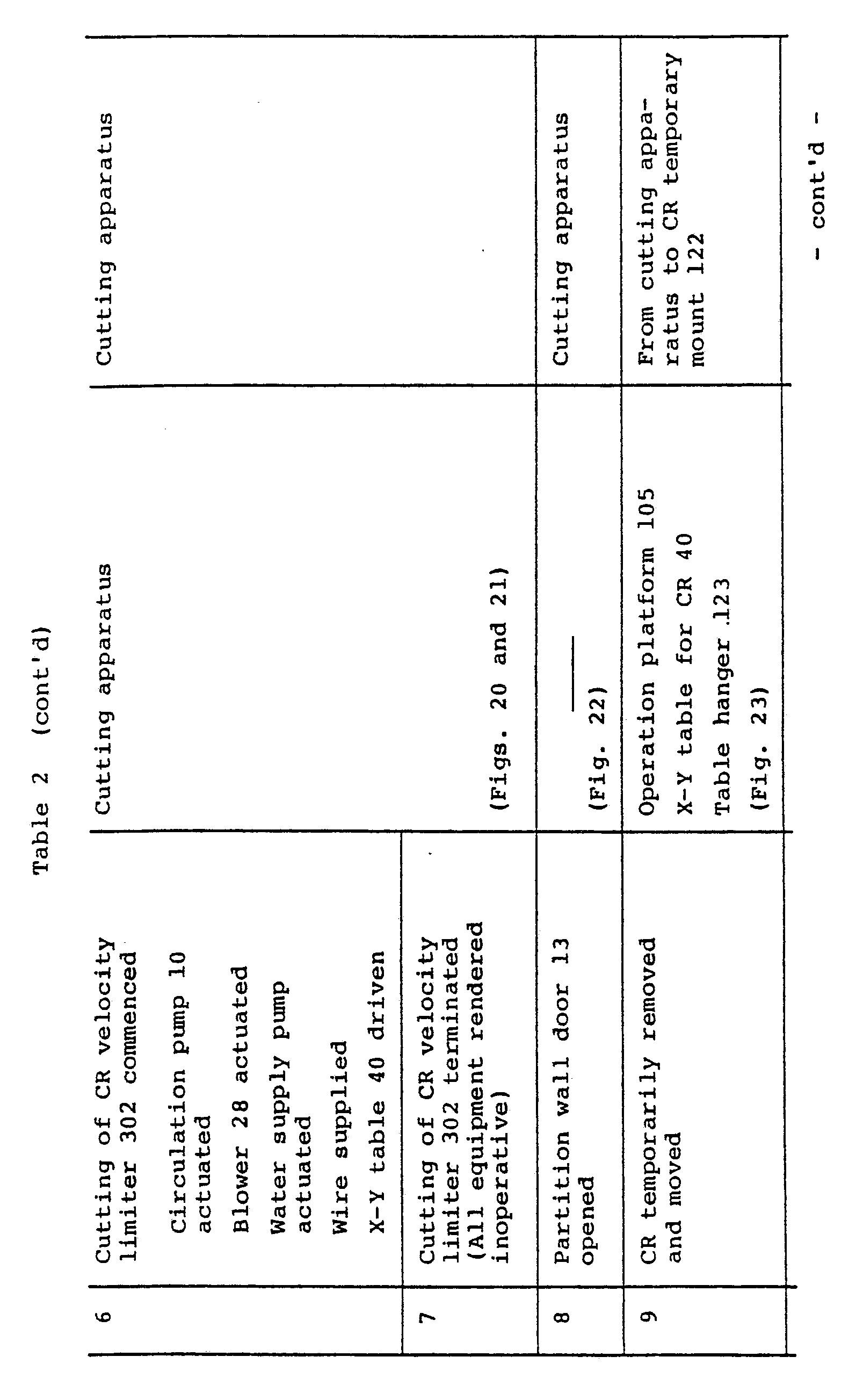
CR 300 is moved by aCR handling tool 121 to atemporary mount 122 to which the X-Y table 40 for theCR 300 is attached by means of atable hanger 123 as shown in Fig. 18, and theCR 300 is clamped in place by the clamp means 49 (Figs. 7 and 8) of the X-Y table 40. At this time, the support table 15 for the FCB and CR has been moved from theupper cart 3 of the cutting apparatus. Then, as shown in Fig. 19, the X-Y table 40 for the CR is lifted together with theCR 300 by thetable hanger 123 from aCR storage rack 124 and moved into the space defined by thepartition wall 7 after thedoor 13 is opened, to be mounted on theupper cart 3 of the cutting apparatus. At this time, theCR 300 is supported such that its lower end clears thelower cart 4. Thereafter, the upper andlower carts CR 300 at which thevelocity limiter 302 is severed from theblade 301 is disposed at the same elevation as the cutting torches 6a and 6b. Thedrive motors CR 300 horizontally to cut off thevelocity limiter 302. Thevelocity limiter 302 severed from theblade 301 in this way is moved, as shown in Fig. 21, by the guiding and moving member 19 (Fig. 3) on thelower cart 4 into thevelocity limiter housing 18. - Referring to Fig. 22, the
blade 301 of theCR 300 from which thevelocity limiter section 302 is severed is detached together with the X-Y table 40 for the CR from the cutting apparatus, and moved to thetemporary mount 122 for the CR as shown in Fig. 23. Then, the support table 15 for the FCB and CR is mounted on theupper cart 3 of the cutting apparatus by an operation shown in Fig. 24. Thereafter, theCR 300 on thetemporary mount 122 for the CR is withdrawn from the X-Y table 40 for the CR as shown in Fig. 25 and inserted through an upper portion of the cutting apparatus and clamped in position by the clamp means 14 (Fig. 3) on the lower cart 3 (Fig. 26). - The upper and
lower carts CR 300 axially through the center of a tie rod by means of thecutting torch 6a. After the cutting operation is finished, theelongated split portion 303 of the CR is withdrawn by the elongated splitportion handling tool 111 as shown in Fig. 27, and an inserted in an elongatedsplit portion housing 126 as shown in Fig. 28. - The process steps for the cutting operations described hereinabove are shown tables as follows:


- In the embodiment shown and described hereinabove, the FCB and CR can be cut into elongated split portions of an 1 shape in cross section. Thus, by storing these elongated split portions in the housing rack as shown in Fig. 28, storing efficiency can be improved from about fourfold to sevenfold as compared with storing the FCB and CR in their original shapes. The cutting operation for cutting the FCB and CR can be performed in the water by remote control by means of the same cutting apparatus. Combined with a shortening of time required for performing the cutting operation made possible by a reduction in the length of the cutting line, this has improved operation efficiency while reducing the risk of exposure of the operator to radiation.
- In the embodiment shown and described hereinabove, the cutting has been described has being performed by a jet cutting technique. This is because this cutting technique best serves the purpose and suits the condition. However, the invention is not limited to this specific cutting technique when the method according to the invention is carried into practice, and any other suitable cutting technique may be used without departing from the scope of the invention.
- When the
velocity limiter 302 of the CR is severed from theblade 301, thecutting torch 6a can be moved horizontally. When this is the case, the X-Y table 40 for the CR can be eliminated, but means should be provided for moving thecutting torch 6a and lines connected to thecutting torch 6a should be rendered flexible. - The cutting apparatus shown and described hereinabove may be simplified as a cutting apparatus exclusively for cutting the CR by doing without the function for cutting the FCB for which a solution has already been found.
- Fig. 29 shows another embodiment of the cutting apparatus in conformity with the invention which is essentially no different from the embodiment in a condition in which the X-Y table 40 for the CR is attached to the upper cart qq of the cutting apparatus.
- Referring to Fig. 30, the
CR 300 is formed with a square opening at an upper portion of thevelocity limiter 302 which is of a crisscross cross-sectional shape. When cutting is performed, theCR 300 is clamped on to the table 40 by clamp means and moved, as shown in Fig. 31 in an X-Y direction together with the table 40, to thereby cut each of portions of theblade 301 of the crisscross shape. At this time, the two cuttingtorches blade 301 of the crisscross shape. After thevelocity limiter 302 is cut off, the center of theblade 301 of the crisscross shape is moved toward thetorch 6a and cutting is effected by feeding a cutting material to thetorch 6a. - In this embodiment, the need to replace the support table 15 for both the FCB and CR by the X-Y table 40 exclusively for the CR is eliminated, thereby improving the operability of the CR cutting operation.
- When the cutting method according to the invention is used, the FCB and CR can be cut into split portions of a substantially similar shape that suits storing by effecting cutting along a substantially short cutting line.
- In the cutting apparatus according to the invention described hereinabove and shown in the drawings, the FCB and CR can be cut in the water by remote control into portions of a substantially similar shape or the CR can be cut at least into portions of an L-shape in cross section.
Claims (8)
Applications Claiming Priority (2)
| Application Number | Priority Date | Filing Date | Title |
|---|---|---|---|
| JP58060814A JPS59187298A (en) | 1983-04-08 | 1983-04-08 | Method and device for cutting high level radioactive solid waste |
| JP60814/83 | 1983-04-08 |
Publications (3)
| Publication Number | Publication Date |
|---|---|
| EP0125470A2 EP0125470A2 (en) | 1984-11-21 |
| EP0125470A3 EP0125470A3 (en) | 1985-08-07 |
| EP0125470B1 true EP0125470B1 (en) | 1988-08-24 |
Family
ID=13153189
Family Applications (1)
| Application Number | Title | Priority Date | Filing Date |
|---|---|---|---|
| EP84103805A Expired EP0125470B1 (en) | 1983-04-08 | 1984-04-06 | Method of and apparatus for cutting high-activity solid waste |
Country Status (5)
| Country | Link |
|---|---|
| US (1) | US4643845A (en) |
| EP (1) | EP0125470B1 (en) |
| JP (1) | JPS59187298A (en) |
| DE (1) | DE3473677D1 (en) |
| ES (1) | ES8605651A1 (en) |
Families Citing this family (20)
| Publication number | Priority date | Publication date | Assignee | Title |
|---|---|---|---|---|
| JPH0631861B2 (en) * | 1985-02-01 | 1994-04-27 | 株式会社日立製作所 | Radioactive solid waste cutting device |
| US4747995A (en) * | 1985-06-10 | 1988-05-31 | Widder Corporation | Velocity limiter shear for BWR control rods |
| US5055236A (en) * | 1985-09-16 | 1991-10-08 | Krieg Adrian H | Method and apparatus for underwater remote controlled radioactive waste reduction of boiling water nuclear reactor control rods |
| US4822555A (en) * | 1987-06-18 | 1989-04-18 | Nuclear Services Company | Container for plate-like objects |
| US4788027A (en) * | 1987-07-14 | 1988-11-29 | Krieg Adrian H | Method and means for remote removal of guide balls from nuclear reactor control rods |
| FR2673033B1 (en) * | 1991-02-19 | 1994-07-22 | Framatome Sa | METHOD AND DEVICE FOR DISMANTLING THE INTERNAL EQUIPMENT OF A NUCLEAR REACTOR COOLED WITH WATER. |
| EP0566960A2 (en) * | 1992-04-22 | 1993-10-27 | Siemens Aktiengesellschaft | Chopping ans wrapping of fuel assembly ducts or similar nuclear reactor structure elements |
| US5247549A (en) * | 1992-10-16 | 1993-09-21 | General Electric Company | Control rod spacer pad |
| US5247545A (en) * | 1992-10-19 | 1993-09-21 | General Electric Company | Control blade servicing assembly |
| JP3029186B2 (en) * | 1995-02-14 | 2000-04-04 | 川崎重工業株式会社 | Underwater cutting equipment for highly radioactive solid waste |
| DE19700651C1 (en) * | 1997-01-10 | 1998-09-03 | Siemens Ag | Compression of control and absorber elements to be disposed of from light water reactors |
| JP3249421B2 (en) * | 1997-03-17 | 2002-01-21 | 三菱重工業株式会社 | Underwater cutting method and device |
| FR2767220B1 (en) * | 1997-08-07 | 1999-10-01 | Atea | PROCESS FOR RENOVATION OF A NUCLEAR FUEL ASSEMBLY STORAGE RACK |
| US20050220254A1 (en) * | 2003-04-08 | 2005-10-06 | Framatome Anp Gmbh | Method and device for dismantling a control element of a boiling water reactor |
| WO2005059816A1 (en) * | 2003-12-19 | 2005-06-30 | Vodafone K.K. | Information display method, mobile information apparatus, and noncontact communication device |
| JP4500224B2 (en) * | 2005-07-04 | 2010-07-14 | 日立Geニュークリア・エナジー株式会社 | Volume reduction system and method for used control rod |
| JP6001075B2 (en) * | 2011-09-22 | 2016-10-05 | ウエスチングハウス・エレクトリック・カンパニー・エルエルシー | A method for reducing the storage volume of boiling water reactor control rods. |
| US9275766B2 (en) * | 2011-11-21 | 2016-03-01 | Westinghouse Electric Company Llc | Apparatus for vertically segmenting a boiling water reactor control rod blade |
| US10375901B2 (en) | 2014-12-09 | 2019-08-13 | Mtd Products Inc | Blower/vacuum |
| JP7157712B2 (en) * | 2019-07-26 | 2022-10-20 | 株式会社日立プラントコンストラクション | How to store radioactive waste |
Family Cites Families (18)
| Publication number | Priority date | Publication date | Assignee | Title |
|---|---|---|---|---|
| US2990169A (en) * | 1959-08-17 | 1961-06-27 | Lionel H Wheeler | Machine for cutting pipe |
| US3797813A (en) * | 1970-12-22 | 1974-03-19 | V Roesel | Control apparatus for metalworking tools |
| US4295401A (en) * | 1976-07-29 | 1981-10-20 | Nus Corporation | Apparatus for disposing of radioactive fuel channels |
| JPS5327795A (en) * | 1976-08-24 | 1978-03-15 | Nuclear Assurance Corp | Method and device for cutting nuclear fuel chanel |
| US4277361A (en) * | 1977-05-04 | 1981-07-07 | Atlantic Richfield Company | Ventilating system for reprocessing of nuclear fuel rods |
| JPS5526407A (en) * | 1978-08-14 | 1980-02-25 | Hitachi Ltd | Method and device of processing cylindrical body |
| JPS5526436A (en) * | 1978-08-16 | 1980-02-25 | Hitachi Ltd | Device of processing cylindrical body of fuel assembly |
| JPS5925480B2 (en) * | 1978-10-20 | 1984-06-18 | 株式会社日立製作所 | Cylindrical body processing equipment |
| JPS55122197A (en) * | 1979-03-14 | 1980-09-19 | Hitachi Ltd | Device for handling radioactive material |
| JPS5811306B2 (en) * | 1979-06-29 | 1983-03-02 | 三井造船株式会社 | Underwater cutting device for radioactively contaminated metal |
| JPS56128262A (en) * | 1980-02-07 | 1981-10-07 | Budd Co | Roof structure for railway rolling stock |
| JPS60640B2 (en) * | 1980-07-22 | 1985-01-09 | 三井造船株式会社 | Underwater cutting device for radioactive metal waste |
| JPS5744498U (en) * | 1980-08-27 | 1982-03-11 | ||
| US4434092A (en) * | 1981-04-06 | 1984-02-28 | Paul Mary | Method for preparing radioactive control rods from nuclear reactors for storage or disposal |
| IT1168096B (en) * | 1981-06-11 | 1987-05-20 | Innocenti Santeustacchio Spa | CONTINUOUS CROSS-CAGE ROLLING MACHINE FOR THE PRODUCTION OF PIPES WITHOUT WELDING |
| SE426889B (en) * | 1981-06-12 | 1983-02-14 | Asea Atom Ab | DEVICE FOR REDUCING THE SCREW VOLUME WHEN SCRATCHING A MULTIPLE PACKAGE WHICH IS USED IN A NUCLEAR REACTOR'S FUEL CARTRIDGES |
| DE3209439A1 (en) * | 1981-12-23 | 1983-09-29 | Klöckner-Werke AG, 4100 Duisburg | Apparatus for working a pipe, in particular an automatically controlled pipe flame-cutting machine |
| US4511499A (en) * | 1982-03-18 | 1985-04-16 | Westinghouse Electric Corp. | Apparatus for dismantling and disposing of fuel assemblies |
-
1983
- 1983-04-08 JP JP58060814A patent/JPS59187298A/en active Granted
-
1984
- 1984-04-05 ES ES531315A patent/ES8605651A1/en not_active Expired
- 1984-04-06 EP EP84103805A patent/EP0125470B1/en not_active Expired
- 1984-04-06 DE DE8484103805T patent/DE3473677D1/en not_active Expired
- 1984-04-06 US US06/597,738 patent/US4643845A/en not_active Expired - Lifetime
Also Published As
| Publication number | Publication date |
|---|---|
| EP0125470A3 (en) | 1985-08-07 |
| DE3473677D1 (en) | 1988-09-29 |
| ES8605651A1 (en) | 1986-03-16 |
| JPS59187298A (en) | 1984-10-24 |
| JPH0349080B2 (en) | 1991-07-26 |
| US4643845A (en) | 1987-02-17 |
| EP0125470A2 (en) | 1984-11-21 |
| ES531315A0 (en) | 1986-03-16 |
Similar Documents
| Publication | Publication Date | Title |
|---|---|---|
| EP0125470B1 (en) | Method of and apparatus for cutting high-activity solid waste | |
| US4511499A (en) | Apparatus for dismantling and disposing of fuel assemblies | |
| US5263062A (en) | Process and apparatus for dismantling the internal equipment of a water-cooled nuclear reactor | |
| JP2001239462A (en) | Ultra-high pressure polishing water-jet cutting machine | |
| KR0158198B1 (en) | Device for cutting a bundle of rods | |
| US4857262A (en) | System for singularizing fuel rods in a fuel element | |
| US3827579A (en) | Irradiated fuel processing system | |
| JPS63215997A (en) | Method and device for cutting irradiated fuel element | |
| JP2010223923A (en) | Underwater volume reduction system for spent control rod | |
| US5633902A (en) | Method and apparatus for dismantling fuel storage racks | |
| JP4837582B2 (en) | Radioactive solid waste cutting apparatus and radioactive solid waste cutting method | |
| US5203244A (en) | Device for cutting up a component of a nuclear reactor | |
| CN211265663U (en) | Automatic disassembling equipment for square-shell battery cell | |
| JPH0768776B2 (en) | Cutting and demolition equipment for cylindrical structures | |
| EP0538206B1 (en) | A remotely controlled apparatus for the sealing and cutting of internally contaminated pipes | |
| JPH07111477B2 (en) | Cutting and demolition equipment for cylindrical structures | |
| JP3438549B2 (en) | Mechanical cutting equipment | |
| JPS59162495A (en) | Cutting device for high level radioactive solid waste | |
| CN220591956U (en) | Gantry linear motor laser cutting equipment | |
| CN215941711U (en) | Energy-saving cutting equipment for steel structure machining | |
| JPS5811306B2 (en) | Underwater cutting device for radioactively contaminated metal | |
| JPH0348799A (en) | Method and device for shredding channel box after use | |
| KR100884127B1 (en) | Checkerboard shear volume reduction system | |
| CN219857804U (en) | Abandoned iron nail collecting device for construction site | |
| JPH0711593B2 (en) | Radioactive solid waste cutting device |
Legal Events
| Date | Code | Title | Description |
|---|---|---|---|
| PUAI | Public reference made under article 153(3) epc to a published international application that has entered the european phase |
Free format text: ORIGINAL CODE: 0009012 |
|
| AK | Designated contracting states |
Designated state(s): DE SE |
|
| PUAL | Search report despatched |
Free format text: ORIGINAL CODE: 0009013 |
|
| AK | Designated contracting states |
Designated state(s): DE SE |
|
| 17P | Request for examination filed |
Effective date: 19850809 |
|
| 17Q | First examination report despatched |
Effective date: 19860728 |
|
| GRAA | (expected) grant |
Free format text: ORIGINAL CODE: 0009210 |
|
| AK | Designated contracting states |
Kind code of ref document: B1 Designated state(s): DE SE |
|
| REF | Corresponds to: |
Ref document number: 3473677 Country of ref document: DE Date of ref document: 19880929 |
|
| PGFP | Annual fee paid to national office [announced via postgrant information from national office to epo] |
Ref country code: SE Payment date: 19890307 Year of fee payment: 6 |
|
| PGFP | Annual fee paid to national office [announced via postgrant information from national office to epo] |
Ref country code: DE Payment date: 19890505 Year of fee payment: 6 |
|
| PLBE | No opposition filed within time limit |
Free format text: ORIGINAL CODE: 0009261 |
|
| STAA | Information on the status of an ep patent application or granted ep patent |
Free format text: STATUS: NO OPPOSITION FILED WITHIN TIME LIMIT |
|
| 26N | No opposition filed | ||
| PG25 | Lapsed in a contracting state [announced via postgrant information from national office to epo] |
Ref country code: SE Effective date: 19900407 |
|
| PG25 | Lapsed in a contracting state [announced via postgrant information from national office to epo] |
Ref country code: DE Effective date: 19910101 |
|
| EUG | Se: european patent has lapsed |
Ref document number: 84103805.2 Effective date: 19910115 |