EP0125450A2 - Microwave cavity tuner - Google Patents
Microwave cavity tuner Download PDFInfo
- Publication number
- EP0125450A2 EP0125450A2 EP84103597A EP84103597A EP0125450A2 EP 0125450 A2 EP0125450 A2 EP 0125450A2 EP 84103597 A EP84103597 A EP 84103597A EP 84103597 A EP84103597 A EP 84103597A EP 0125450 A2 EP0125450 A2 EP 0125450A2
- Authority
- EP
- European Patent Office
- Prior art keywords
- tubular member
- cavity
- hole
- shoulder
- tube
- Prior art date
- Legal status (The legal status is an assumption and is not a legal conclusion. Google has not performed a legal analysis and makes no representation as to the accuracy of the status listed.)
- Granted
Links
- 239000000463 material Substances 0.000 claims abstract description 4
- 239000003989 dielectric material Substances 0.000 claims description 4
- 229910001374 Invar Inorganic materials 0.000 abstract description 7
- 239000010453 quartz Substances 0.000 abstract description 3
- 229910052594 sapphire Inorganic materials 0.000 abstract description 3
- 239000010980 sapphire Substances 0.000 abstract description 3
- VYPSYNLAJGMNEJ-UHFFFAOYSA-N silicon dioxide Inorganic materials O=[Si]=O VYPSYNLAJGMNEJ-UHFFFAOYSA-N 0.000 abstract description 3
- 239000013078 crystal Substances 0.000 abstract 1
- 229910052751 metal Inorganic materials 0.000 description 7
- 239000002184 metal Substances 0.000 description 7
- 230000000694 effects Effects 0.000 description 2
- RYGMFSIKBFXOCR-UHFFFAOYSA-N Copper Chemical compound [Cu] RYGMFSIKBFXOCR-UHFFFAOYSA-N 0.000 description 1
- 229910052782 aluminium Inorganic materials 0.000 description 1
- XAGFODPZIPBFFR-UHFFFAOYSA-N aluminium Chemical compound [Al] XAGFODPZIPBFFR-UHFFFAOYSA-N 0.000 description 1
- 229910052802 copper Inorganic materials 0.000 description 1
- 239000010949 copper Substances 0.000 description 1
- 230000007423 decrease Effects 0.000 description 1
- 230000002939 deleterious effect Effects 0.000 description 1
- PCHJSUWPFVWCPO-UHFFFAOYSA-N gold Chemical compound [Au] PCHJSUWPFVWCPO-UHFFFAOYSA-N 0.000 description 1
- 229910052737 gold Inorganic materials 0.000 description 1
- 239000010931 gold Substances 0.000 description 1
- 239000011295 pitch Substances 0.000 description 1
Images
Classifications
-
- H—ELECTRICITY
- H01—ELECTRIC ELEMENTS
- H01P—WAVEGUIDES; RESONATORS, LINES, OR OTHER DEVICES OF THE WAVEGUIDE TYPE
- H01P7/00—Resonators of the waveguide type
- H01P7/06—Cavity resonators
-
- H—ELECTRICITY
- H01—ELECTRIC ELEMENTS
- H01J—ELECTRIC DISCHARGE TUBES OR DISCHARGE LAMPS
- H01J23/00—Details of transit-time tubes of the types covered by group H01J25/00
- H01J23/16—Circuit elements, having distributed capacitance and inductance, structurally associated with the tube and interacting with the discharge
- H01J23/18—Resonators
- H01J23/20—Cavity resonators; Adjustment or tuning thereof
Definitions
- the invention relates to microwave cavity resonators in which a tuning element protrudes into the cavity.
- the invention is especially applicable to the problem of frequency stability of such resonators.
- temperature variations cause dimensional changes which produce corresponding variations in the inductance and capacitance of the cavity. This produces a corresponding frequency change.
- a material of low thermal expansion coefficient, such as INVAR in the tuning element to limit its length change. Consequently, as the cavity size increases the distance between the end of the tuning element and the opposite wall of the cavity increases. Accordingly the capacitance changes oppositely to the inductance and so tends to stabilize the frequency.
- One tuning mechanism using this principle has an externally screwthreaded tube projecting into the cavity. Its external end is closed and an INVAR rod is slidably housed within the tube so that one of its ends abuts the closed end of the tube and its other end projects some distance beyond the end of the tube and impinges upon a diaphragm supported from the end of the tube by a cylindrical bellows.
- the length of the tube will vary more than that of the INVAR rod and the differences are accommodated by the bellows.
- a microwave device comprising a housing having a cavity therein.
- a hole extends through one wall of the cavity and a tubular member having a low thermal expansion coefficient, for example INVAR (Trade Mark) extends from the hole into the cavity.
- the end of the tubular member in the hole is positively located, preferably by pressure contact, against axial movement relative thereto.
- a tuner element of dielectric material for example a slug of quartz or sapphire, protrudes from the other end of the tubular element. The tuner element is adjustable axially relative to the tubular member to effect tuning of the device.
- the tubular member has an external lip within the hole.
- the hole has a reduced diameter portion providing a shoulder.
- the lip bears against the shoulder to positively locate the tubular member axially relative to cavity.
- the lip may then be urged against the shoulder by a spring washer acting between the lip and a bush or holder screwed into the outer end of the hole.
- the tuner element engages the interior of the tubular member at a position spaced from its end.
- the tuner element may be a slug of lesser diameter than the interior of the tubular member, mounted on a metal boss which is arranged to cooperate with the interior of the tubular element.
- the metal boss is externally screwthreaded and the tubular member correspondingly internally screwthreaded. Rotation of the boss to adjust the position of the slug of dielectric material may then be by means of a tool inserted through the tubular member and, where applicable, external bush or holder.
- the movement of the boss preferably is limited so that it is always shielded by the tubular member from R.F. energy in the cavity.
- the microwave cavity resonator shown in the drawing comprises an aluminum block 10 containing a cavity 12 of parallelepiped form with radiused corners when viewed as shown.
- a hole 14 extends through one wall of the cavity 12 from the outside of the block 10. The interior of the hole 14 is counterbored from the outer end to form a reduced diameter portion 16 adjacent the cavity 12.
- a tubular member 18 projects from the hole 14 more than halfway across the cavity 12.
- the tubular member 18 is made of a material having a low thermal coefficient of expansion such as INVAR (Trade Mark) which has a coefficient of about 0.6 ppm/ o C.
- the exterior of the tubular member 18 is stepped to provide a lip 20 adjacent its end in the hole 14.
- the lip 20 bears against the radially extending shoulder 22 between the reduced diameter portion 16 and the greater diameter portion of the hole 14.
- a conical spring washer 24 acts between the end of the tubular member 18 and the opposed end of a bush 26, which is located in the outer part of the hole 14.
- the bush 26 is externally screwthreaded as at 28 to engage a correspondingly screwthreaded portion 30 of the hole 14. When the bush 26 is screwed into the hole 14 it urges the lip 20 into firm abutment with the shoulder 22 to locate the tubular member 18 positively and accurately relative to the cavity 12.
- the member 18 is coated with copper and gold, at least its exterior between the lip 20 and the end in the cavity, and its interior adjacent that end.
- the lesser diameter part of the tubular member 18 has a diameter somewhat less than that of the reduced diameter part 16 of the hole 14, resulting in a clearance therebetween so that the only contact between the tubular member 18 and the housing or block 10 is at the lip 20/shoulder 22 interface. This ensures a repeatable and predictable path for the R.F. energy.
- a tuner element 32 is located in the projecting part of the tubular member 18.
- the tuner element 32 comprises a short cylindrical slug or rod 34 of quartz, sapphire or other suitable dielectric material mounted at one end upon a screwthreaded metal support member 36 in the form of a metal boss.
- the support member 36 comprises two screwthreaded parts 38, 40 interconnected by an intermediate radially-slotted part 42.
- the parts 38, 40 cooperate with the interior of the tubular member 18, which is correspondingly screwthreaded.
- the slotted part 42 is axially compressed to offset the pitches of the screwthreads on parts 38 and 40. Consequently the support member 36 is self-locking when in the tube 18.
- the end of the member 36 directed towards the hole 14 is slotted so that it can be rotated by a screwdriver inserted through the bush 26.
- the configuration of the member 36 is such that it serves as a spring-loaded, self-locking, constant torque drive mechanism.
- the screwthreaded part of the tubular member 18 stops some distance from its internal end leaving a short section 44 of slightly lesser diameter through which the tuning slug 34 extends without touching.
- This arrangement ensures that-the support member or metal boss 36, and hence the only contact between the tuning slug 34 and the tubular member 18, is always well within the tubular member 18 and so shielded from the R.F. field. Otherwise current could flow through the screwthreaded connection between the metal boss 36 and the tube and lead to an unreliable contact which would change with time, temperature, humidity or vibration.
- tuning adjustments are made by screwing the support member 36, and with it the tuning slug 34, along the tubular member 18. Tuning is then maintained, despite temperature variations, by virtue of the difference between the temperature coefficients of the cavity and the tubular member 18.
- the size of the cavity increases which increases the inductance of the path taken by R.F. energy.
- the length of the tubular member 18 remains virtually constant so the distance between its end and the opposite wall of the cavity increases. This decreases the capacitance which tends to negate the effect on the frequency of the increase in inductance.
- tubular member can be readily replaced if its internal thread becomes worn or if it is desired to change the frequency to which the cavity can be tuned.
Landscapes
- Control Of Motors That Do Not Use Commutators (AREA)
- Microwave Tubes (AREA)
- Non-Reversible Transmitting Devices (AREA)
- Input Circuits Of Receivers And Coupling Of Receivers And Audio Equipment (AREA)
Abstract
Description
- The invention relates to microwave cavity resonators in which a tuning element protrudes into the cavity.
- The invention is especially applicable to the problem of frequency stability of such resonators. Usually temperature variations cause dimensional changes which produce corresponding variations in the inductance and capacitance of the cavity. This produces a corresponding frequency change. Hitherto the problem has been addressed by using a material of low thermal expansion coefficient, such as INVAR in the tuning element to limit its length change. Consequently, as the cavity size increases the distance between the end of the tuning element and the opposite wall of the cavity increases. Accordingly the capacitance changes oppositely to the inductance and so tends to stabilize the frequency.
- One tuning mechanism using this principle has an externally screwthreaded tube projecting into the cavity. Its external end is closed and an INVAR rod is slidably housed within the tube so that one of its ends abuts the closed end of the tube and its other end projects some distance beyond the end of the tube and impinges upon a diaphragm supported from the end of the tube by a cylindrical bellows. In this arrangement the length of the tube will vary more than that of the INVAR rod and the differences are accommodated by the bellows.
- Such an arrangement has been satisfactory for some applications, typically analogue, but is not satisfactory for more stringent applications, such as digital radio where stability is critical because a slight phase variation can cause a complete loss of information. In particular, problems arise because the bellows is relatively floppy, so the contact between it and the end of the INVAR tube may vary due to temperature changes or vibration. Also, soldered joints are required between the bellows and the tube, and metal-to-metal contact between the tube and the cavity is by way of their respective screwthreads. These may cause variations in the path taken by the R.F. energy with consequent deleterious effects upon stability.
- The present invention seeks to overcome these problems and to this end provides a microwave device comprising a housing having a cavity therein. A hole extends through one wall of the cavity and a tubular member having a low thermal expansion coefficient, for example INVAR (Trade Mark) extends from the hole into the cavity. The end of the tubular member in the hole is positively located, preferably by pressure contact, against axial movement relative thereto. A tuner element of dielectric material, for example a slug of quartz or sapphire, protrudes from the other end of the tubular element. The tuner element is adjustable axially relative to the tubular member to effect tuning of the device.
- In preferred embodiments the tubular member has an external lip within the hole. The hole has a reduced diameter portion providing a shoulder. The lip bears against the shoulder to positively locate the tubular member axially relative to cavity. The lip may then be urged against the shoulder by a spring washer acting between the lip and a bush or holder screwed into the outer end of the hole.
- Preferably the tuner element engages the interior of the tubular member at a position spaced from its end. For example, the tuner element may be a slug of lesser diameter than the interior of the tubular member, mounted on a metal boss which is arranged to cooperate with the interior of the tubular element. Conveniently the metal boss is externally screwthreaded and the tubular member correspondingly internally screwthreaded. Rotation of the boss to adjust the position of the slug of dielectric material may then be by means of a tool inserted through the tubular member and, where applicable, external bush or holder. The movement of the boss preferably is limited so that it is always shielded by the tubular member from R.F. energy in the cavity.
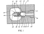
- An embodiment of the invention will now be described by way of example only and with reference to the accompanying drawing, which is a cross-sectional view of a microwave cavity resonator.
- The microwave cavity resonator shown in the drawing comprises an
aluminum block 10 containing acavity 12 of parallelepiped form with radiused corners when viewed as shown. Ahole 14 extends through one wall of thecavity 12 from the outside of theblock 10. The interior of thehole 14 is counterbored from the outer end to form a reduceddiameter portion 16 adjacent thecavity 12. Atubular member 18 projects from thehole 14 more than halfway across thecavity 12. Thetubular member 18 is made of a material having a low thermal coefficient of expansion such as INVAR (Trade Mark) which has a coefficient of about 0.6 ppm/oC. - The exterior of the
tubular member 18 is stepped to provide alip 20 adjacent its end in thehole 14. Thelip 20 bears against the radially extendingshoulder 22 between the reduceddiameter portion 16 and the greater diameter portion of thehole 14. A conical spring washer 24 acts between the end of thetubular member 18 and the opposed end of abush 26, which is located in the outer part of thehole 14. Thebush 26 is externally screwthreaded as at 28 to engage a correspondingly screwthreadedportion 30 of thehole 14. When thebush 26 is screwed into thehole 14 it urges thelip 20 into firm abutment with theshoulder 22 to locate thetubular member 18 positively and accurately relative to thecavity 12. Themember 18 is coated with copper and gold, at least its exterior between thelip 20 and the end in the cavity, and its interior adjacent that end. - The lesser diameter part of the
tubular member 18 has a diameter somewhat less than that of the reduceddiameter part 16 of thehole 14, resulting in a clearance therebetween so that the only contact between thetubular member 18 and the housing orblock 10 is at thelip 20/shoulder 22 interface. This ensures a repeatable and predictable path for the R.F. energy. - A
tuner element 32 is located in the projecting part of thetubular member 18. Thetuner element 32 comprises a short cylindrical slug orrod 34 of quartz, sapphire or other suitable dielectric material mounted at one end upon a screwthreadedmetal support member 36 in the form of a metal boss. Thesupport member 36 comprises two screwthreadedparts part 42. Theparts tubular member 18, which is correspondingly screwthreaded. Theslotted part 42 is axially compressed to offset the pitches of the screwthreads onparts support member 36 is self-locking when in thetube 18. The end of themember 36 directed towards thehole 14 is slotted so that it can be rotated by a screwdriver inserted through thebush 26. The configuration of themember 36 is such that it serves as a spring-loaded, self-locking, constant torque drive mechanism. - The screwthreaded part of the
tubular member 18 stops some distance from its internal end leaving ashort section 44 of slightly lesser diameter through which thetuning slug 34 extends without touching. This arrangement ensures that-the support member ormetal boss 36, and hence the only contact between thetuning slug 34 and thetubular member 18, is always well within thetubular member 18 and so shielded from the R.F. field. Otherwise current could flow through the screwthreaded connection between themetal boss 36 and the tube and lead to an unreliable contact which would change with time, temperature, humidity or vibration. - In operation, tuning adjustments are made by screwing the
support member 36, and with it thetuning slug 34, along thetubular member 18. Tuning is then maintained, despite temperature variations, by virtue of the difference between the temperature coefficients of the cavity and thetubular member 18. Thus, as the temperature increases, the size of the cavity increases which increases the inductance of the path taken by R.F. energy. However, the length of thetubular member 18 remains virtually constant so the distance between its end and the opposite wall of the cavity increases. This decreases the capacitance which tends to negate the effect on the frequency of the increase in inductance. - An advantage of embodiments of the invention is that the tubular member can be readily replaced if its internal thread becomes worn or if it is desired to change the frequency to which the cavity can be tuned.
Claims (6)
Priority Applications (1)
| Application Number | Priority Date | Filing Date | Title |
|---|---|---|---|
| AT84103597T ATE41559T1 (en) | 1983-05-16 | 1984-03-31 | TUNING ELEMENT FOR A MICROWAVE CAVITY RESONATOR. |
Applications Claiming Priority (2)
| Application Number | Priority Date | Filing Date | Title |
|---|---|---|---|
| CA428267 | 1983-05-16 | ||
| CA000428267A CA1192635A (en) | 1983-05-16 | 1983-05-16 | Microwave cavity tuner |
Publications (3)
| Publication Number | Publication Date |
|---|---|
| EP0125450A2 true EP0125450A2 (en) | 1984-11-21 |
| EP0125450A3 EP0125450A3 (en) | 1985-11-13 |
| EP0125450B1 EP0125450B1 (en) | 1989-03-15 |
Family
ID=4125254
Family Applications (1)
| Application Number | Title | Priority Date | Filing Date |
|---|---|---|---|
| EP84103597A Expired EP0125450B1 (en) | 1983-05-16 | 1984-03-31 | Microwave cavity tuner |
Country Status (6)
| Country | Link |
|---|---|
| US (1) | US4535308A (en) |
| EP (1) | EP0125450B1 (en) |
| JP (1) | JPS59221004A (en) |
| AT (1) | ATE41559T1 (en) |
| CA (1) | CA1192635A (en) |
| DE (1) | DE3477316D1 (en) |
Cited By (4)
| Publication number | Priority date | Publication date | Assignee | Title |
|---|---|---|---|---|
| FR2670321A1 (en) * | 1990-12-11 | 1992-06-12 | Thomson Tubes Electroniques | CAVITY HYPERFREQUENCY TUBE WITH DIELECTRIC STRUCTURE AND METHOD OF MAKING TUBE CAVITY. |
| WO2009027622A1 (en) * | 2007-08-30 | 2009-03-05 | Isotek Electronics Limited | A tuneable filter and a method of tuning such a filter |
| EP2838105A1 (en) * | 2013-08-16 | 2015-02-18 | Microelectronics Technology Inc. | Microwave resonant cavity |
| US9112251B2 (en) | 2013-08-14 | 2015-08-18 | Microelectronics Technology, Inc. | Microwave resonant cavity |
Families Citing this family (9)
| Publication number | Priority date | Publication date | Assignee | Title |
|---|---|---|---|---|
| FR2627329B1 (en) * | 1988-02-12 | 1990-03-23 | Alcatel Espace | DIELECTRIC RESONATOR FILTER |
| DE4107631C2 (en) * | 1991-03-09 | 1994-12-15 | Bruker Analytische Messtechnik | Resonator for electron spin resonance spectroscopy |
| DE4107628A1 (en) * | 1991-03-09 | 1992-09-10 | Bruker Analytische Messtechnik | HF resonator for electron spin resonance measurements - has tuning element in form of dielectric wobbler moved periodically through resonance mode field by drive system |
| JP3069475B2 (en) * | 1993-09-30 | 2000-07-24 | シャープ株式会社 | Converter for satellite broadcasting reception |
| SE508680C2 (en) * | 1996-06-19 | 1998-10-26 | Ericsson Telefon Ab L M | Integrated filters |
| US5889448A (en) * | 1997-06-05 | 1999-03-30 | Illinois Superconductor Corporation | Resonator mounting mechanism |
| US6362708B1 (en) | 1998-05-21 | 2002-03-26 | Lucix Corporation | Dielectric resonator tuning device |
| SE516862C2 (en) * | 2000-07-14 | 2002-03-12 | Allgon Ab | Reconciliation screw device and method and resonator |
| US6750730B2 (en) | 2002-05-01 | 2004-06-15 | Marconi Communications Gmbh | Tuning arrangement for a microwave device |
Family Cites Families (7)
| Publication number | Priority date | Publication date | Assignee | Title |
|---|---|---|---|---|
| US2124029A (en) * | 1935-06-08 | 1938-07-19 | Rca Corp | Frequency control line and circuit |
| US3311839A (en) * | 1965-12-16 | 1967-03-28 | Northern Electric Co | Compensated tunable cavity with single variable element |
| US3541479A (en) * | 1968-01-17 | 1970-11-17 | Webb James E | Tuning arrangement for an electron discharge device or the like |
| DE2045560C3 (en) * | 1970-09-15 | 1978-03-09 | Standard Elektrik Lorenz Ag, 7000 Stuttgart | Microwave filters made from cuboid cavity resonators |
| US4127834A (en) * | 1977-08-29 | 1978-11-28 | Motorola, Inc. | Temperature compensating apparatus for microwave oscillators and the like |
| FR2477783A1 (en) * | 1980-03-04 | 1981-09-11 | Thomson Csf | VARIABLE CAPABILITY ADAPTER DEVICE AND TUNABLE HYPERFREQUENCY FILTER HAVING AT LEAST ONE SUCH DEVICE |
| FR2507018A1 (en) * | 1981-06-02 | 1982-12-03 | Thomson Csf | MICROWAVE RESONATOR OF THE VARIABLE TO DIELECTRIC CAPACITOR TYPE |
-
1983
- 1983-05-16 CA CA000428267A patent/CA1192635A/en not_active Expired
- 1983-09-15 US US06/532,388 patent/US4535308A/en not_active Expired - Lifetime
-
1984
- 1984-03-31 EP EP84103597A patent/EP0125450B1/en not_active Expired
- 1984-03-31 AT AT84103597T patent/ATE41559T1/en not_active IP Right Cessation
- 1984-03-31 DE DE8484103597T patent/DE3477316D1/en not_active Expired
- 1984-05-16 JP JP59096744A patent/JPS59221004A/en active Granted
Cited By (6)
| Publication number | Priority date | Publication date | Assignee | Title |
|---|---|---|---|---|
| FR2670321A1 (en) * | 1990-12-11 | 1992-06-12 | Thomson Tubes Electroniques | CAVITY HYPERFREQUENCY TUBE WITH DIELECTRIC STRUCTURE AND METHOD OF MAKING TUBE CAVITY. |
| EP0490741A1 (en) * | 1990-12-11 | 1992-06-17 | Thomson Tubes Electroniques | Microwave tube with a cavity having a dielectric structure, and method of making a tube cavity |
| WO2009027622A1 (en) * | 2007-08-30 | 2009-03-05 | Isotek Electronics Limited | A tuneable filter and a method of tuning such a filter |
| GB2452293B (en) * | 2007-08-30 | 2011-09-28 | Isotek Electronics Ltd | A tuneable filter and a method of tuning such a filter |
| US9112251B2 (en) | 2013-08-14 | 2015-08-18 | Microelectronics Technology, Inc. | Microwave resonant cavity |
| EP2838105A1 (en) * | 2013-08-16 | 2015-02-18 | Microelectronics Technology Inc. | Microwave resonant cavity |
Also Published As
| Publication number | Publication date |
|---|---|
| CA1192635A (en) | 1985-08-27 |
| JPS59221004A (en) | 1984-12-12 |
| JPH0436481B2 (en) | 1992-06-16 |
| EP0125450B1 (en) | 1989-03-15 |
| EP0125450A3 (en) | 1985-11-13 |
| ATE41559T1 (en) | 1989-04-15 |
| DE3477316D1 (en) | 1989-04-20 |
| US4535308A (en) | 1985-08-13 |
Similar Documents
| Publication | Publication Date | Title |
|---|---|---|
| US4535308A (en) | Microwave cavity tuner | |
| US6255922B1 (en) | Microwave resonator with dielectric tuning body resiliently secured to a movable rod by spring means | |
| US6734766B2 (en) | Microwave filter having a temperature compensating element | |
| US4521754A (en) | Tuning and temperature compensation arrangement for microwave resonators | |
| US2578608A (en) | Screw and nut mechanism | |
| EP0211455B1 (en) | Microwave metallic cavity | |
| US9748622B2 (en) | Tunable high frequency filter | |
| US4423398A (en) | Internal bi-metallic temperature compensating device for tuned cavities | |
| US5039966A (en) | Temperature-compensated tuning screw for cavity filters | |
| US2486129A (en) | Temperature compensating | |
| US4570137A (en) | Lumped-mode resonator | |
| US3034078A (en) | Temperature compensated microwave cavity | |
| US3063030A (en) | Temperature compensated resonant cavities | |
| US4205286A (en) | Temperature stabilized helical resonator | |
| US4464699A (en) | Shock proof adjustable low-loss capacitor | |
| US3173106A (en) | Microwave oscillator with bimetal temperature compensation | |
| US4415949A (en) | Air trimmer capacitor | |
| US3528042A (en) | Temperature compensated waveguide cavity | |
| US20060255888A1 (en) | Radio-frequency filter | |
| US2774017A (en) | Trimmer | |
| US2717364A (en) | Temperature compensation of permeability tuned circuits | |
| US3274464A (en) | Temperature compensating trimmer capacitor | |
| US3825862A (en) | Helical resonator | |
| US3058042A (en) | Adjustable electrical reactance unit | |
| US4459564A (en) | Waveguide tunable oscillator cavity structure |
Legal Events
| Date | Code | Title | Description |
|---|---|---|---|
| PUAI | Public reference made under article 153(3) epc to a published international application that has entered the european phase |
Free format text: ORIGINAL CODE: 0009012 |
|
| AK | Designated contracting states |
Designated state(s): AT DE FR GB NL SE |
|
| PUAL | Search report despatched |
Free format text: ORIGINAL CODE: 0009013 |
|
| AK | Designated contracting states |
Designated state(s): AT DE FR GB NL SE |
|
| 17P | Request for examination filed |
Effective date: 19851230 |
|
| 17Q | First examination report despatched |
Effective date: 19870422 |
|
| GRAA | (expected) grant |
Free format text: ORIGINAL CODE: 0009210 |
|
| AK | Designated contracting states |
Kind code of ref document: B1 Designated state(s): AT DE FR GB NL SE |
|
| REF | Corresponds to: |
Ref document number: 41559 Country of ref document: AT Date of ref document: 19890415 Kind code of ref document: T |
|
| REF | Corresponds to: |
Ref document number: 3477316 Country of ref document: DE Date of ref document: 19890420 |
|
| ET | Fr: translation filed | ||
| PLBE | No opposition filed within time limit |
Free format text: ORIGINAL CODE: 0009261 |
|
| STAA | Information on the status of an ep patent application or granted ep patent |
Free format text: STATUS: NO OPPOSITION FILED WITHIN TIME LIMIT |
|
| 26N | No opposition filed | ||
| PGFP | Annual fee paid to national office [announced via postgrant information from national office to epo] |
Ref country code: AT Payment date: 19920311 Year of fee payment: 9 |
|
| PGFP | Annual fee paid to national office [announced via postgrant information from national office to epo] |
Ref country code: SE Payment date: 19920319 Year of fee payment: 9 |
|
| PGFP | Annual fee paid to national office [announced via postgrant information from national office to epo] |
Ref country code: NL Payment date: 19920331 Year of fee payment: 9 |
|
| PG25 | Lapsed in a contracting state [announced via postgrant information from national office to epo] |
Ref country code: AT Effective date: 19930331 |
|
| PG25 | Lapsed in a contracting state [announced via postgrant information from national office to epo] |
Ref country code: SE Effective date: 19930401 |
|
| PG25 | Lapsed in a contracting state [announced via postgrant information from national office to epo] |
Ref country code: NL Effective date: 19931001 |
|
| NLV4 | Nl: lapsed or anulled due to non-payment of the annual fee | ||
| EUG | Se: european patent has lapsed |
Ref document number: 84103597.5 Effective date: 19931110 |
|
| PGFP | Annual fee paid to national office [announced via postgrant information from national office to epo] |
Ref country code: FR Payment date: 19980310 Year of fee payment: 15 |
|
| PGFP | Annual fee paid to national office [announced via postgrant information from national office to epo] |
Ref country code: GB Payment date: 19980323 Year of fee payment: 15 |
|
| PGFP | Annual fee paid to national office [announced via postgrant information from national office to epo] |
Ref country code: DE Payment date: 19980403 Year of fee payment: 15 |
|
| PG25 | Lapsed in a contracting state [announced via postgrant information from national office to epo] |
Ref country code: GB Free format text: LAPSE BECAUSE OF NON-PAYMENT OF DUE FEES Effective date: 19990331 |
|
| GBPC | Gb: european patent ceased through non-payment of renewal fee |
Effective date: 19990331 |
|
| PG25 | Lapsed in a contracting state [announced via postgrant information from national office to epo] |
Ref country code: FR Free format text: LAPSE BECAUSE OF NON-PAYMENT OF DUE FEES Effective date: 19991130 |
|
| REG | Reference to a national code |
Ref country code: FR Ref legal event code: ST |
|
| PG25 | Lapsed in a contracting state [announced via postgrant information from national office to epo] |
Ref country code: DE Free format text: LAPSE BECAUSE OF NON-PAYMENT OF DUE FEES Effective date: 20000101 |