EP0125085B1 - Variable inductor mechanism - Google Patents
Variable inductor mechanism Download PDFInfo
- Publication number
- EP0125085B1 EP0125085B1 EP19840302898 EP84302898A EP0125085B1 EP 0125085 B1 EP0125085 B1 EP 0125085B1 EP 19840302898 EP19840302898 EP 19840302898 EP 84302898 A EP84302898 A EP 84302898A EP 0125085 B1 EP0125085 B1 EP 0125085B1
- Authority
- EP
- European Patent Office
- Prior art keywords
- coil
- tape
- mechanism according
- influencing means
- inductance
- Prior art date
- Legal status (The legal status is an assumption and is not a legal conclusion. Google has not performed a legal analysis and makes no representation as to the accuracy of the status listed.)
- Expired
Links
- 230000007246 mechanism Effects 0.000 title claims description 44
- 239000004020 conductor Substances 0.000 claims description 25
- 239000000463 material Substances 0.000 claims description 6
- 210000000707 wrist Anatomy 0.000 claims description 6
- 239000002184 metal Substances 0.000 claims description 5
- 229910052751 metal Inorganic materials 0.000 claims description 5
- 239000004642 Polyimide Substances 0.000 claims description 4
- 229920003055 poly(ester-imide) Polymers 0.000 claims description 4
- 229920001721 polyimide Polymers 0.000 claims description 4
- 239000000126 substance Substances 0.000 claims description 4
- 230000007423 decrease Effects 0.000 claims description 3
- RYGMFSIKBFXOCR-UHFFFAOYSA-N Copper Chemical compound [Cu] RYGMFSIKBFXOCR-UHFFFAOYSA-N 0.000 claims description 2
- 229910052802 copper Inorganic materials 0.000 claims description 2
- 239000010949 copper Substances 0.000 claims description 2
- 230000001419 dependent effect Effects 0.000 claims description 2
- 239000010410 layer Substances 0.000 description 22
- 238000010276 construction Methods 0.000 description 10
- 230000036039 immunity Effects 0.000 description 3
- 239000000758 substrate Substances 0.000 description 3
- 239000002344 surface layer Substances 0.000 description 3
- 230000008901 benefit Effects 0.000 description 2
- 230000004907 flux Effects 0.000 description 2
- 238000006842 Henry reaction Methods 0.000 description 1
- XEEYBQQBJWHFJM-UHFFFAOYSA-N Iron Chemical group [Fe] XEEYBQQBJWHFJM-UHFFFAOYSA-N 0.000 description 1
- 230000009471 action Effects 0.000 description 1
- 239000003990 capacitor Substances 0.000 description 1
- 230000008878 coupling Effects 0.000 description 1
- 230000001808 coupling effect Effects 0.000 description 1
- 238000010168 coupling process Methods 0.000 description 1
- 238000005859 coupling reaction Methods 0.000 description 1
- 238000006073 displacement reaction Methods 0.000 description 1
- 238000010348 incorporation Methods 0.000 description 1
- 239000012811 non-conductive material Substances 0.000 description 1
- 230000035699 permeability Effects 0.000 description 1
- 229920003223 poly(pyromellitimide-1,4-diphenyl ether) Polymers 0.000 description 1
- 239000012260 resinous material Substances 0.000 description 1
- 238000005096 rolling process Methods 0.000 description 1
- 230000005236 sound signal Effects 0.000 description 1
- 229910000859 α-Fe Inorganic materials 0.000 description 1
Images

Classifications
-
- H—ELECTRICITY
- H01—ELECTRIC ELEMENTS
- H01F—MAGNETS; INDUCTANCES; TRANSFORMERS; SELECTION OF MATERIALS FOR THEIR MAGNETIC PROPERTIES
- H01F29/00—Variable transformers or inductances not covered by group H01F21/00
- H01F29/08—Variable transformers or inductances not covered by group H01F21/00 with core, coil, winding, or shield movable to offset variation of voltage or phase shift, e.g. induction regulators
- H01F29/12—Variable transformers or inductances not covered by group H01F21/00 with core, coil, winding, or shield movable to offset variation of voltage or phase shift, e.g. induction regulators having movable coil, winding, or part thereof; having movable shield
-
- H—ELECTRICITY
- H01—ELECTRIC ELEMENTS
- H01F—MAGNETS; INDUCTANCES; TRANSFORMERS; SELECTION OF MATERIALS FOR THEIR MAGNETIC PROPERTIES
- H01F21/00—Variable inductances or transformers of the signal type
- H01F21/02—Variable inductances or transformers of the signal type continuously variable, e.g. variometers
-
- H—ELECTRICITY
- H01—ELECTRIC ELEMENTS
- H01F—MAGNETS; INDUCTANCES; TRANSFORMERS; SELECTION OF MATERIALS FOR THEIR MAGNETIC PROPERTIES
- H01F21/00—Variable inductances or transformers of the signal type
- H01F21/02—Variable inductances or transformers of the signal type continuously variable, e.g. variometers
- H01F21/10—Variable inductances or transformers of the signal type continuously variable, e.g. variometers by means of a movable shield
Definitions
- This invention relates to a variable inductor mechanism and in particular to a tuning mechanism for tuning a receiver, such as a radio receiver.
- the mechanism is especially suited to miniaturisation and has been particularly designed for tuning a wrist mounted radio. It will be appreciated, however, that the invention is not limited to such a use, and could, for example, be used for any of the normal inductance uses, such as for the adjustment or tuning of audio signals, filters and the like.
- the resonant frequency of an UC tuned circuit is altered by varying the inductance of a coil or varying capacitance of a capacitor, which forms part of a tuning circuit.
- the present invention is particularly concerned with altering the inductance of a coil.
- GB-A-1097303 also discloses a device for varying the mutual coupling between first and second coils by passing a screen member made of a material of high conductivity between the two coils.
- the discs or screen member have a high mass and moment of inertia and are not suitable for miniaturisation.
- the present invention seeks to provide a variable inductor mechanism which is compact and in which the adjusting means has negligible mass and moment of inertia and lends itself to miniaturisation.
- variable inductor mechanism comprising a coil and influencing means to influence the inductance of the coil, in dependence on the transverse position of the influencing means relative to the coil axis, characterised in that the influencing means is supported on or forms part of a flexible tape movable longitudinally in a direction generally transverse to the axis of the coil.
- the influencing means is movable along a path which intersects the axis of the coil at right angles.
- the influencing means is applied to selected parts of a surface of the tape in such a way that its influence on the coil will vary in dependence upon which portion of the tape is aligned with the longitudinal axis of the coil.
- the tape is in the form of an endless tape loop. While it is envisaged that the tape may itself be formed entirely of a conductive material, it is preferred that it is made of non-conductive material with a conductive layer on one of its surfaces.
- the endless tape loop is entrained around and engages with a drive sprocket and passes around a smooth roller which is sprung so as to act as an idler and keep the tape in tension.
- the tape loop is formed of a thin polyester or polyimide material (10-20 pm), and the conductive layer is formed of copper or another metal etched onto a surface of the tape,. or any other substance capable of varying the' inductance of the coil, and the conductive layer is wedge shaped, with the longitudinal axis of the wedge extending along the axis of the tape, so that as the tape is advanced past the longitudinal axis of the coil, the width of the conductive layer will increase or decrease uniformly, thus varying the inductance or coupled inductance of the coil.
- the physical position of the sprocket is such that the tape always runs over the smooth surface of the coil former and thus remains at a fixed distance from the coil.
- a tuning scale is also printed onto the tape, and the arrangement may be such that as the lower run of the tape loop passes across the coil axis, the scale will be visible and move along the upper run of the loop.
- the mechanism is particularly suited for use as a tuning mechanism for a miniature radio receiver which can be worn on a person's wrist, and the scale may therefore be located beneath a window in a casing, and the drive sprocket may be connected to a control knob located on the outside of the casing.
- Backlash in the mechanism is reduced to a minimum by providing domed sprocket teeth on the sprocket, which engage with an interference fit in holes in the tape.
- the frequency characteristic will be governed by the "shape" of that portion of the "conductor layer” which intersects the flux lines of the coil.
- the tape loop has very low mechanical inertia, resulting in a high degree of immunity to mechanical vibrations. Also, by printing the tuning scale on the tape, maximum use is made of the tape, and additional moving parts are not required, and an integral tuning mechanism and frequency display is provided with a long length tuning scale.
- the influence of the influencing means on the inductance of the coil can be varied by providing different patterns of the "conductor layer". While the standard configuration would normally have a wedge shaped pattern, it would be possible to have two wedge shaped, generally parallel spaced wedge portions. This has the advantage that tolerances to displacement of the influencing means perpendicular to the longitudinal axis of the wedge can be reduced.
- the "conductor layer" instead of being a continuous wedge, could be made up of a plurality of spaced "conductor” segments, dots, bars, etc., of different size, width, depth, spacing, density, etc.
- the "conductor layer” need not just be a surface layer on the tape. It could comprise a part of the tape extending throughout the total width of the sheet- like material of the tape. It is even envisaged that the whole tape could be metallic, and of varying width and/or thickness, thus having, over any chosen area, a different inductance or coupling effect which would influence the inductance of the coil as it was moved past the coil axis.
- the tape need not be in a closed loop, and it is envisaged that other configurations are possible.
- the tuning mechanism comprises a coil 1 mounted on a substrate 3.
- the coil is connected in known manner to other components of a tuning circuit for a radio receiver, and for a miniature receiver for which the present invention is designed (but this is not its only use), the other circuit components (not shown) are sufficiently small to be mounted on the substrate 3 to either side of the coil 1.
- the other main component of the tuning mechanism is a coil inductance influencing means, in the form of an endless loop of tape 5, entrained around a drive sprocket 7 and an idler roller 9, each of which is supported in known manner for rotation about a suitable axis extending generally parallel to the substrate 3.
- the roller 9 is kept in place by a tension spring 11 which may also be used to tension the tape loop 5.
- the drive sprocket 7 may be replaced by a friction roller drive and instead of providing an idler roller 9, a fixed rolling surface such as a shaft, could be provided.
- a friction roller drive instead of providing an idler roller 9, a fixed rolling surface such as a shaft, could be provided.
- the lower run of the tape 5 runs across the top of the coil 1, and although not essential, in the illustrated construction, lies generally in a plane extending normal to the longitudinal axis of the coil 1.
- the tape 5 is preferably formed of a thin (10-20 pm) polyester or polyimide material, such as Du Pont's KAPTON, and an essential requirement is that at least the part of the tape or a surface layer thereon which moves across the end of the coil (or in a generally transverse direction adjacent the end) is of a conductive nature, i.e. acts as a conductor.
- a conductive nature i.e. acts as a conductor.
- One preferred construction is illustrated in Figure 2, with the polyester or polyimide portion indicated at 13, and a metallic portion shown at 15.
- the metallic portion could be a surface layer adhered or deposited on the portion 13, or it could be, e.g. copper or another good conductor etched into portion 13.
- Other constructions are possible; for example, the whole tape could be metallic.
- the coupled inductance of the tape should vary over its surface area.
- this is achieved by the metallic portion 15 being of a particular pattern, in this case of a uniformly increasing width from one end to the other.
- the lower run of the tape can be divided up into a very large number of regions, five of which B, C, D, E and F are notionally illustrated in Figure 2.
- This "conductor layer” portion depending on its area, will thus intersect lines of flux emanating from the coil 1 when this is connected into the tuning circuit and the resonant frequency of the tuning circuit will thus be altered in dependence on the coupled inductance of the portion of the "conductor layer” part of the tape 5 overlying the coil.
- At least one row of equally spaced holes 19 is formed in tape 5, which mesh with domed sprocket teeth 21 (see Figure 3) in the drive sprocket 7.
- the whole tuner mechanism will have a very low backlash, and of course very low mechanical inertia, resulting in a high degree of immunity to mechanical vibrations.
- a further important feature of the invention is the provision of a tuning scale 10 on the tape 5 (see Figures 5 and 6).
- the scale 10 is on the upper face of the upper run 12 of the loop, and when the whole mechanism is surrounded by a casing 14, the shaft 8 for the tuning knob projects through an aperture in a side wall 16 of the casing 14, and a window 18, which may have a hairline reference line, is provided in the top wall 20 of the casing 14, through which the tuning scale 10 can be read, as it is advanced, by rotation of the shaft 8, past the window 18.
- a finite length of the tape movable from one "spool" to another "spool” could be used.
- the frequency characteristics of a tuning circuit is influenced by the area (shape) of the portion of the "conductor layer" on the influencing means, i.e. tape carrier, overlying the coil 1.
- the whole mechanism has a minimum number of moving parts with the tuner scale 10 integral with the influencing means.
- the mechanism is very compact, has a minimum of mechanical inertia and hence has a high degree of immunity to vibration, which is a big advantage since, if it is used as a miniature radio tuner, it allows a moving coil loudspeaker to be located very close to the mechanism. Also, there is no backlash in the tuning mechanism.
- the invention has been designed specifically for a miniature radio receiver, and it is envisaged that the coil 1 need only be about 4 mm in diameter and 2 mm in height, with the total length about 16 mm and width about 8 mm, and no more than about 4 mm high.
- the initial inductance of the coil 1 could be adjusted by providing a metal ring around the lower end of the coil.
- the spacing of the influencing means from the coil will affect the coupled inductance of the coil, as will the permeability of the coil core.
- the range of coil inductance and absolute values can be affected by additional coils, rings and cores, in accordance with known practice.
- the coil core could, for example, be a ferrite/iron core, and the coil is not limited to a small length/diameter ratio.
- the wedge shape of the "conductor layers” 15 shown in Figure 2 could be altered as desired to vary the inductance of coil 1.
- the preferred construction, together with four of many possible alternative shapes or patterns are illustrated in Figure 4, where like or similar parts are identified by the same reference numerals.
- the second construction comprises two split wedge shapes, and instead of having the "conductor layer(s)" 15 passing centrally over the coil axis, has the layers 15 passing off centre, and this means that if the influencing means becomes laterally offset relative to the coil axis, although one of the wedge portions 15 will move away from the coil axis, it will be compensated for by the other portion 15 moving nearer the coil axis. It is of course also possible to vary the distance of the influencing means from the coil as the former is moved transversely across the coil axis.
- the "conductor layer" of the influencing means could be duplicated so that there is a portion associated with each coil.
- the coils can be ganged in a tuning circuit and it is even possible to arrange for the inductance of one coil to increase while the other decreases, by using a single influencing means as described with two "conductor layers". It is even envisaged that a split coil, partly above and partly below the influencing means, could be used, or that two coils could be used which are antiphase connected.
- the essence of the invention is to provide a substantially flat "conductor layer" which either forms or is mounted on a surface of a tape, which can be moved generally transverse to the axis of a coil, and which acts as an influencing means to vary the inductance or coupled inductance of the coil.
- the "conductor layer” is any substance capable of varying the inductance of the coil, and by varying the "intensity" of this layer, e.g. over the surface of the tape, the transverse location of the "conductor layer” relative to the coil axis will influence the inductance of the coil, which forms part of an inductance tuning circuit.
- the "intensity" can be changed by variations in shape, size, density, spacing of the said substance, e.g.
- a drive shaft with a suitable operating knob at one end may be used to impart drive by means of friction to the loop.
- a sleeve of resinous material may be forced onto a central region of the drive shaft and after the loop has been mounted on the drive shaft and a further idler shaft, the shafts may be mounted in a resiliently deformable frame, one of the shafts being located between suitable forked bearings extending outwardly from one end of the frame and the other shaft being located between similar bearings at the other end of the frame but projecting at right angles to the first mentioned forks with the second shaft being located within the forks by means of a generally over-centre action.
Landscapes
- Engineering & Computer Science (AREA)
- Power Engineering (AREA)
- Coils Or Transformers For Communication (AREA)
Description
- This invention relates to a variable inductor mechanism and in particular to a tuning mechanism for tuning a receiver, such as a radio receiver. The mechanism is especially suited to miniaturisation and has been particularly designed for tuning a wrist mounted radio. It will be appreciated, however, that the invention is not limited to such a use, and could, for example, be used for any of the normal inductance uses, such as for the adjustment or tuning of audio signals, filters and the like.
- It is a well known fact that the resonant frequency of an UC tuned circuit, such as that used for tuning a radio receiver, is altered by varying the inductance of a coil or varying capacitance of a capacitor, which forms part of a tuning circuit. The present invention is particularly concerned with altering the inductance of a coil.
- Various proposals have been put forward for varying the inductance of coils using a disc rotatable in a plane extending at right angles to the axis of the coil. For example, in DE-C-669078 a coil has its inductance varied by means of a metal disc of variable thickness which is rotatable about a central axis by means of a control knob. Hence, the inductance of the coil is influenced in dependence upon the transverse position of the influencing means (the metal disc) relative to the coil axis. The disc is guided by plates extending across the end of the coil and the whole mechanism is so large that it is capable of achieving changes in inductance in the range of 5-36 Henrys. In US-A-3155931, the rate of variation of the inductance of the coil is dependent on the distance and thickness of a rotatable disc from the coil axis. GB-A-1097303 also discloses a device for varying the mutual coupling between first and second coils by passing a screen member made of a material of high conductivity between the two coils.
- In the above three prior art constructions, the discs or screen member have a high mass and moment of inertia and are not suitable for miniaturisation. The present invention seeks to provide a variable inductor mechanism which is compact and in which the adjusting means has negligible mass and moment of inertia and lends itself to miniaturisation.
- According to the present invention, we provide a variable inductor mechanism comprising a coil and influencing means to influence the inductance of the coil, in dependence on the transverse position of the influencing means relative to the coil axis, characterised in that the influencing means is supported on or forms part of a flexible tape movable longitudinally in a direction generally transverse to the axis of the coil.
- Preferably, the influencing means is movable along a path which intersects the axis of the coil at right angles.
- According to one embodiment of the invention, the influencing means is applied to selected parts of a surface of the tape in such a way that its influence on the coil will vary in dependence upon which portion of the tape is aligned with the longitudinal axis of the coil.
- Preferably, the tape is in the form of an endless tape loop. While it is envisaged that the tape may itself be formed entirely of a conductive material, it is preferred that it is made of non-conductive material with a conductive layer on one of its surfaces.
- In a preferred construction, the endless tape loop is entrained around and engages with a drive sprocket and passes around a smooth roller which is sprung so as to act as an idler and keep the tape in tension.
- Preferably, the tape loop is formed of a thin polyester or polyimide material (10-20 pm), and the conductive layer is formed of copper or another metal etched onto a surface of the tape,. or any other substance capable of varying the' inductance of the coil, and the conductive layer is wedge shaped, with the longitudinal axis of the wedge extending along the axis of the tape, so that as the tape is advanced past the longitudinal axis of the coil, the width of the conductive layer will increase or decrease uniformly, thus varying the inductance or coupled inductance of the coil.
- In the preferred arrangement, the physical position of the sprocket is such that the tape always runs over the smooth surface of the coil former and thus remains at a fixed distance from the coil.
- Preferably, a tuning scale is also printed onto the tape, and the arrangement may be such that as the lower run of the tape loop passes across the coil axis, the scale will be visible and move along the upper run of the loop. The mechanism is particularly suited for use as a tuning mechanism for a miniature radio receiver which can be worn on a person's wrist, and the scale may therefore be located beneath a window in a casing, and the drive sprocket may be connected to a control knob located on the outside of the casing.
- Although described for use with a receiver, it should be noted that the mechanism could alternatively be used to tune a transmitter, and for many other inductance uses.
- Backlash in the mechanism is reduced to a minimum by providing domed sprocket teeth on the sprocket, which engage with an interference fit in holes in the tape.
- It will thus be appreciated that if the coil is connected to other components of a tuning circuit, e.g. of a radio receiver, which may be located around the coil beneath the influencing means, the frequency characteristic will be governed by the "shape" of that portion of the "conductor layer" which intersects the flux lines of the coil.
- The tape loop has very low mechanical inertia, resulting in a high degree of immunity to mechanical vibrations. Also, by printing the tuning scale on the tape, maximum use is made of the tape, and additional moving parts are not required, and an integral tuning mechanism and frequency display is provided with a long length tuning scale.
- It will be appreciated that the influence of the influencing means on the inductance of the coil can be varied by providing different patterns of the "conductor layer". While the standard configuration would normally have a wedge shaped pattern, it would be possible to have two wedge shaped, generally parallel spaced wedge portions. This has the advantage that tolerances to displacement of the influencing means perpendicular to the longitudinal axis of the wedge can be reduced. Alternatively, the "conductor layer", instead of being a continuous wedge, could be made up of a plurality of spaced "conductor" segments, dots, bars, etc., of different size, width, depth, spacing, density, etc.
- It should also be borne in mind that the "conductor layer" need not just be a surface layer on the tape. It could comprise a part of the tape extending throughout the total width of the sheet- like material of the tape. It is even envisaged that the whole tape could be metallic, and of varying width and/or thickness, thus having, over any chosen area, a different inductance or coupling effect which would influence the inductance of the coil as it was moved past the coil axis.
- It should also be realised that the tape need not be in a closed loop, and it is envisaged that other configurations are possible.
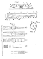
- A tuning mechanism in accordance with the present invention is now described by way of example, with reference to the accompanying drawings, in which:-
- FIGURE 1 is a partly schematic side elevation of a preferred construction;
- FIGURE 2 is a plan view of part of the tape (represented by arrows A-A in Figure 1) used in the mechanism of Figure 1;
- FIGURE 3 is a schematic side elevation of a drive sprocket;
- FIGURES 4a-4e show various alternative conductor patterns applicable to the tape;
- FIGURE 5 is a perspective view of a modified tuning mechanism' for incorporation in a wrist watch; and
- FIGURE 6 is a perspective view of the body of a wrist watch incorporating the mechanism of Figure 5.
- Referring to Figures 1 and 2 of the drawings, the tuning mechanism comprises a
coil 1 mounted on asubstrate 3. The coil is connected in known manner to other components of a tuning circuit for a radio receiver, and for a miniature receiver for which the present invention is designed (but this is not its only use), the other circuit components (not shown) are sufficiently small to be mounted on thesubstrate 3 to either side of thecoil 1. The other main component of the tuning mechanism is a coil inductance influencing means, in the form of an endless loop oftape 5, entrained around adrive sprocket 7 and anidler roller 9, each of which is supported in known manner for rotation about a suitable axis extending generally parallel to thesubstrate 3. Theroller 9 is kept in place by atension spring 11 which may also be used to tension thetape loop 5. Thedrive sprocket 7 may be replaced by a friction roller drive and instead of providing anidler roller 9, a fixed rolling surface such as a shaft, could be provided. As can be seen from Figure 1, the lower run of thetape 5 runs across the top of thecoil 1, and although not essential, in the illustrated construction, lies generally in a plane extending normal to the longitudinal axis of thecoil 1. - The
tape 5 is preferably formed of a thin (10-20 pm) polyester or polyimide material, such as Du Pont's KAPTON, and an essential requirement is that at least the part of the tape or a surface layer thereon which moves across the end of the coil (or in a generally transverse direction adjacent the end) is of a conductive nature, i.e. acts as a conductor. One preferred construction is illustrated in Figure 2, with the polyester or polyimide portion indicated at 13, and a metallic portion shown at 15. The metallic portion could be a surface layer adhered or deposited on theportion 13, or it could be, e.g. copper or another good conductor etched intoportion 13. Other constructions are possible; for example, the whole tape could be metallic. - An essential requirement is that the coupled inductance of the tape should vary over its surface area. In the preferred construction, this is achieved by the
metallic portion 15 being of a particular pattern, in this case of a uniformly increasing width from one end to the other. It will thus be appreciated that the lower run of the tape can be divided up into a very large number of regions, five of which B, C, D, E and F are notionally illustrated in Figure 2. By rotating thesprocket 7 and moving the tape across the end of thecoil 1, any one of these regions will overlie the end of the coil, and the area of the metallic, i.e. conductive, tape portion 15 (the "conductor layer") will be considerably greater when region B overlies the coil end than the area when region F overlies the end of thecoil 1. This "conductor layer" portion, depending on its area, will thus intersect lines of flux emanating from thecoil 1 when this is connected into the tuning circuit and the resonant frequency of the tuning circuit will thus be altered in dependence on the coupled inductance of the portion of the "conductor layer" part of thetape 5 overlying the coil. - In order to advance the
tape 5 past the end of thecoil 1, it is necessary to rotatesprocket 7. This can be achieved by keying the sprocket on ashaft 8 to which a control knob (not shown) may be fixed. Rotation of the knob will rotate the shaft 8 (see Figures 5 and 6). - It is preferred that at least one row of equally spaced holes 19 is formed in
tape 5, which mesh with domed sprocket teeth 21 (see Figure 3) in thedrive sprocket 7. In this way, the whole tuner mechanism will have a very low backlash, and of course very low mechanical inertia, resulting in a high degree of immunity to mechanical vibrations. - A further important feature of the invention is the provision of a
tuning scale 10 on the tape 5 (see Figures 5 and 6). In the illustrated construction, thescale 10 is on the upper face of theupper run 12 of the loop, and when the whole mechanism is surrounded by acasing 14, theshaft 8 for the tuning knob projects through an aperture in aside wall 16 of thecasing 14, and awindow 18, which may have a hairline reference line, is provided in thetop wall 20 of thecasing 14, through which thetuning scale 10 can be read, as it is advanced, by rotation of theshaft 8, past thewindow 18. - As an alternative to using a tape loop or a disc, a finite length of the tape movable from one "spool" to another "spool" could be used.
- It will thus be appreciated that the frequency characteristics of a tuning circuit is influenced by the area (shape) of the portion of the "conductor layer" on the influencing means, i.e. tape carrier, overlying the
coil 1. The whole mechanism has a minimum number of moving parts with thetuner scale 10 integral with the influencing means. As a result, the mechanism is very compact, has a minimum of mechanical inertia and hence has a high degree of immunity to vibration, which is a big advantage since, if it is used as a miniature radio tuner, it allows a moving coil loudspeaker to be located very close to the mechanism. Also, there is no backlash in the tuning mechanism. - Although suited to any type of inductance tuning mechanism or tuner, the invention has been designed specifically for a miniature radio receiver, and it is envisaged that the
coil 1 need only be about 4 mm in diameter and 2 mm in height, with the total length about 16 mm and width about 8 mm, and no more than about 4 mm high. - It is envisaged that the initial inductance of the
coil 1 could be adjusted by providing a metal ring around the lower end of the coil. Furthermore, the spacing of the influencing means from the coil will affect the coupled inductance of the coil, as will the permeability of the coil core. Likewise, the range of coil inductance and absolute values can be affected by additional coils, rings and cores, in accordance with known practice. The coil core could, for example, be a ferrite/iron core, and the coil is not limited to a small length/diameter ratio. - It will of course be appreciated that the wedge shape of the "conductor layers" 15 shown in Figure 2 could be altered as desired to vary the inductance of
coil 1. The preferred construction, together with four of many possible alternative shapes or patterns are illustrated in Figure 4, where like or similar parts are identified by the same reference numerals. The second construction comprises two split wedge shapes, and instead of having the "conductor layer(s)" 15 passing centrally over the coil axis, has thelayers 15 passing off centre, and this means that if the influencing means becomes laterally offset relative to the coil axis, although one of thewedge portions 15 will move away from the coil axis, it will be compensated for by theother portion 15 moving nearer the coil axis. It is of course also possible to vary the distance of the influencing means from the coil as the former is moved transversely across the coil axis. - It will be appreciated that if desired, more than one
coil 1 may be provided, in which case, the "conductor layer" of the influencing means could be duplicated so that there is a portion associated with each coil. Hence, the coils can be ganged in a tuning circuit and it is even possible to arrange for the inductance of one coil to increase while the other decreases, by using a single influencing means as described with two "conductor layers". It is even envisaged that a split coil, partly above and partly below the influencing means, could be used, or that two coils could be used which are antiphase connected. - The essence of the invention is to provide a substantially flat "conductor layer" which either forms or is mounted on a surface of a tape, which can be moved generally transverse to the axis of a coil, and which acts as an influencing means to vary the inductance or coupled inductance of the coil. The "conductor layer" is any substance capable of varying the inductance of the coil, and by varying the "intensity" of this layer, e.g. over the surface of the tape, the transverse location of the "conductor layer" relative to the coil axis will influence the inductance of the coil, which forms part of an inductance tuning circuit. The "intensity" can be changed by variations in shape, size, density, spacing of the said substance, e.g. by giving it a wedge shape, or providing it in the form of dots or bars of different size, shape, spacing, density, or any combination thereof. Of course, at any one location of the influencing means, only a relatively small part of the "conductor layer" is effective in influencing the inductance of the coil.
- Instead of providing a drive sprocket for the tape loop, a drive shaft with a suitable operating knob at one end may be used to impart drive by means of friction to the loop. For this purpose a sleeve of resinous material may be forced onto a central region of the drive shaft and after the loop has been mounted on the drive shaft and a further idler shaft, the shafts may be mounted in a resiliently deformable frame, one of the shafts being located between suitable forked bearings extending outwardly from one end of the frame and the other shaft being located between similar bearings at the other end of the frame but projecting at right angles to the first mentioned forks with the second shaft being located within the forks by means of a generally over-centre action.
Claims (17)
Applications Claiming Priority (2)
| Application Number | Priority Date | Filing Date | Title |
|---|---|---|---|
| GB838312073A GB8312073D0 (en) | 1983-05-03 | 1983-05-03 | Variable inductor mechanism |
| GB8312073 | 1983-05-03 |
Publications (2)
| Publication Number | Publication Date |
|---|---|
| EP0125085A1 EP0125085A1 (en) | 1984-11-14 |
| EP0125085B1 true EP0125085B1 (en) | 1987-07-01 |
Family
ID=10542074
Family Applications (1)
| Application Number | Title | Priority Date | Filing Date |
|---|---|---|---|
| EP19840302898 Expired EP0125085B1 (en) | 1983-05-03 | 1984-04-30 | Variable inductor mechanism |
Country Status (4)
| Country | Link |
|---|---|
| EP (1) | EP0125085B1 (en) |
| JP (1) | JPS6046114A (en) |
| DE (1) | DE3464527D1 (en) |
| GB (1) | GB8312073D0 (en) |
Families Citing this family (1)
| Publication number | Priority date | Publication date | Assignee | Title |
|---|---|---|---|---|
| JPH01219624A (en) * | 1988-02-29 | 1989-09-01 | Nec Home Electron Ltd | Automatic score taking method and apparatus |
Family Cites Families (6)
| Publication number | Priority date | Publication date | Assignee | Title |
|---|---|---|---|---|
| DE669078C (en) * | 1935-01-23 | 1938-12-16 | Telefunken Gmbh | Iron core coil of variable inductance for telecommunication devices, preferably for high frequency receivers |
| US2975384A (en) * | 1954-09-24 | 1961-03-14 | Sprague Electric Co | Toroidal inductor combinations |
| US2882392A (en) * | 1955-03-09 | 1959-04-14 | Rca Corp | Receiver tuned by inductors with tracking by initial positionment of coils on cores |
| US3155931A (en) * | 1960-01-13 | 1964-11-03 | Maeda Hisao | Wide range variable magnetic inductor |
| GB1097303A (en) * | 1963-07-08 | 1968-01-03 | Westinghouse Brake & Signal | Improvements relating to electrical control devices for electrically driven vehicles |
| CH623678A5 (en) * | 1977-09-01 | 1981-06-15 | Max Breitmeier |
-
1983
- 1983-05-03 GB GB838312073A patent/GB8312073D0/en active Pending
-
1984
- 1984-04-27 JP JP8606884A patent/JPS6046114A/en active Granted
- 1984-04-30 EP EP19840302898 patent/EP0125085B1/en not_active Expired
- 1984-04-30 DE DE8484302898T patent/DE3464527D1/en not_active Expired
Also Published As
| Publication number | Publication date |
|---|---|
| EP0125085A1 (en) | 1984-11-14 |
| DE3464527D1 (en) | 1987-08-06 |
| JPH022329B2 (en) | 1990-01-17 |
| JPS6046114A (en) | 1985-03-12 |
| GB8312073D0 (en) | 1983-06-08 |
Similar Documents
| Publication | Publication Date | Title |
|---|---|---|
| CA1063163A (en) | Electromechanical torsional oscillator with resonant frequency and amplitude control | |
| US6215455B1 (en) | Armored magnetic field antenna in printed circuit | |
| JPH04340208A (en) | Guide | |
| US6762656B1 (en) | LC noise filter | |
| JP2000040620A (en) | Inductor and circuit device using the inductor | |
| EP0125085A1 (en) | Variable inductor mechanism | |
| US5832578A (en) | Method of manufacturing a filter by forming strip lines on a substrate and dividing the substrate | |
| US5609946A (en) | High frequency, high density, low profile, magnetic circuit components | |
| US3820045A (en) | Double-tuned circuit device | |
| JP4190695B2 (en) | Antenna sheet and non-contact data carrier | |
| US5101182A (en) | Drop-in magnetically tunable microstrip bandpass filter | |
| US2935707A (en) | Inductive tuning device | |
| JP2662741B2 (en) | Resonator | |
| EP0440334A2 (en) | Dielectric resonant oscillator | |
| US3155931A (en) | Wide range variable magnetic inductor | |
| JPS62169407A (en) | Inductance element | |
| US1702260A (en) | Radio reception device | |
| JP6841135B2 (en) | Coin-shaped IC tag and its manufacturing method | |
| EP1076345A2 (en) | Variable inductance element | |
| US5257004A (en) | Variable passive element | |
| US3947787A (en) | Mechanical TV control unit | |
| JPH0445222Y2 (en) | ||
| JP3307382B2 (en) | Variable inductance element and manufacturing method thereof | |
| JPH10300411A (en) | Non-contact potentiometer | |
| JPH0693588B2 (en) | Frequency adjustment method for LC composite parts |
Legal Events
| Date | Code | Title | Description |
|---|---|---|---|
| PUAI | Public reference made under article 153(3) epc to a published international application that has entered the european phase |
Free format text: ORIGINAL CODE: 0009012 |
|
| AK | Designated contracting states |
Designated state(s): BE DE FR GB IT NL SE |
|
| 17P | Request for examination filed |
Effective date: 19850419 |
|
| 17Q | First examination report despatched |
Effective date: 19860205 |
|
| ITF | It: translation for a ep patent filed | ||
| RAP1 | Party data changed (applicant data changed or rights of an application transferred) |
Owner name: SHAYE COMMUNICATIONS LIMITED |
|
| GRAA | (expected) grant |
Free format text: ORIGINAL CODE: 0009210 |
|
| AK | Designated contracting states |
Kind code of ref document: B1 Designated state(s): BE DE FR GB IT NL SE |
|
| PG25 | Lapsed in a contracting state [announced via postgrant information from national office to epo] |
Ref country code: BE Effective date: 19870701 |
|
| PG25 | Lapsed in a contracting state [announced via postgrant information from national office to epo] |
Ref country code: SE Effective date: 19870731 |
|
| REF | Corresponds to: |
Ref document number: 3464527 Country of ref document: DE Date of ref document: 19870806 |
|
| ET | Fr: translation filed | ||
| PLBE | No opposition filed within time limit |
Free format text: ORIGINAL CODE: 0009261 |
|
| STAA | Information on the status of an ep patent application or granted ep patent |
Free format text: STATUS: NO OPPOSITION FILED WITHIN TIME LIMIT |
|
| 26N | No opposition filed | ||
| ITTA | It: last paid annual fee | ||
| PGFP | Annual fee paid to national office [announced via postgrant information from national office to epo] |
Ref country code: NL Payment date: 19940430 Year of fee payment: 11 |
|
| PG25 | Lapsed in a contracting state [announced via postgrant information from national office to epo] |
Ref country code: NL Effective date: 19951101 |
|
| NLV4 | Nl: lapsed or anulled due to non-payment of the annual fee |
Effective date: 19951101 |
|
| PGFP | Annual fee paid to national office [announced via postgrant information from national office to epo] |
Ref country code: FR Payment date: 19960329 Year of fee payment: 13 |
|
| PGFP | Annual fee paid to national office [announced via postgrant information from national office to epo] |
Ref country code: GB Payment date: 19960423 Year of fee payment: 13 |
|
| PGFP | Annual fee paid to national office [announced via postgrant information from national office to epo] |
Ref country code: DE Payment date: 19960530 Year of fee payment: 13 |
|
| PG25 | Lapsed in a contracting state [announced via postgrant information from national office to epo] |
Ref country code: GB Effective date: 19970430 |
|
| GBPC | Gb: european patent ceased through non-payment of renewal fee |
Effective date: 19970430 |
|
| PG25 | Lapsed in a contracting state [announced via postgrant information from national office to epo] |
Ref country code: FR Free format text: LAPSE BECAUSE OF NON-PAYMENT OF DUE FEES Effective date: 19971231 |
|
| PG25 | Lapsed in a contracting state [announced via postgrant information from national office to epo] |
Ref country code: DE Free format text: LAPSE BECAUSE OF NON-PAYMENT OF DUE FEES Effective date: 19980101 |
|
| REG | Reference to a national code |
Ref country code: FR Ref legal event code: ST |