EP0124230B1 - Valve - Google Patents
Valve Download PDFInfo
- Publication number
- EP0124230B1 EP0124230B1 EP84301843A EP84301843A EP0124230B1 EP 0124230 B1 EP0124230 B1 EP 0124230B1 EP 84301843 A EP84301843 A EP 84301843A EP 84301843 A EP84301843 A EP 84301843A EP 0124230 B1 EP0124230 B1 EP 0124230B1
- Authority
- EP
- European Patent Office
- Prior art keywords
- valve
- insert
- valve seat
- tubular projection
- bonnet
- Prior art date
- Legal status (The legal status is an assumption and is not a legal conclusion. Google has not performed a legal analysis and makes no representation as to the accuracy of the status listed.)
- Expired
Links
- 230000000717 retained effect Effects 0.000 claims description 2
- 238000005299 abrasion Methods 0.000 claims 1
- 239000012530 fluid Substances 0.000 description 3
- 230000003628 erosive effect Effects 0.000 description 2
- 239000000463 material Substances 0.000 description 2
- 239000003208 petroleum Substances 0.000 description 2
- 229910000679 solder Inorganic materials 0.000 description 2
- 241000282472 Canis lupus familiaris Species 0.000 description 1
- HBMJWWWQQXIZIP-UHFFFAOYSA-N silicon carbide Chemical compound [Si+]#[C-] HBMJWWWQQXIZIP-UHFFFAOYSA-N 0.000 description 1
- 229910010271 silicon carbide Inorganic materials 0.000 description 1
- UONOETXJSWQNOL-UHFFFAOYSA-N tungsten carbide Chemical compound [W+]#[C-] UONOETXJSWQNOL-UHFFFAOYSA-N 0.000 description 1
Images


Classifications
-
- F—MECHANICAL ENGINEERING; LIGHTING; HEATING; WEAPONS; BLASTING
- F16—ENGINEERING ELEMENTS AND UNITS; GENERAL MEASURES FOR PRODUCING AND MAINTAINING EFFECTIVE FUNCTIONING OF MACHINES OR INSTALLATIONS; THERMAL INSULATION IN GENERAL
- F16K—VALVES; TAPS; COCKS; ACTUATING-FLOATS; DEVICES FOR VENTING OR AERATING
- F16K25/00—Details relating to contact between valve members and seats
- F16K25/04—Arrangements for preventing erosion, not otherwise provided for
-
- F—MECHANICAL ENGINEERING; LIGHTING; HEATING; WEAPONS; BLASTING
- F16—ENGINEERING ELEMENTS AND UNITS; GENERAL MEASURES FOR PRODUCING AND MAINTAINING EFFECTIVE FUNCTIONING OF MACHINES OR INSTALLATIONS; THERMAL INSULATION IN GENERAL
- F16K—VALVES; TAPS; COCKS; ACTUATING-FLOATS; DEVICES FOR VENTING OR AERATING
- F16K43/00—Auxiliary closure means in valves, which in case of repair, e.g. rewashering, of the valve, can take over the function of the normal closure means; Devices for temporary replacement of parts of valves for the same purpose
-
- Y—GENERAL TAGGING OF NEW TECHNOLOGICAL DEVELOPMENTS; GENERAL TAGGING OF CROSS-SECTIONAL TECHNOLOGIES SPANNING OVER SEVERAL SECTIONS OF THE IPC; TECHNICAL SUBJECTS COVERED BY FORMER USPC CROSS-REFERENCE ART COLLECTIONS [XRACs] AND DIGESTS
- Y10—TECHNICAL SUBJECTS COVERED BY FORMER USPC
- Y10T—TECHNICAL SUBJECTS COVERED BY FORMER US CLASSIFICATION
- Y10T137/00—Fluid handling
- Y10T137/598—With repair, tapping, assembly, or disassembly means
- Y10T137/5983—Blow out preventer or choke valve device [e.g., oil well flow controlling device, etc.]
-
- Y—GENERAL TAGGING OF NEW TECHNOLOGICAL DEVELOPMENTS; GENERAL TAGGING OF CROSS-SECTIONAL TECHNOLOGIES SPANNING OVER SEVERAL SECTIONS OF THE IPC; TECHNICAL SUBJECTS COVERED BY FORMER USPC CROSS-REFERENCE ART COLLECTIONS [XRACs] AND DIGESTS
- Y10—TECHNICAL SUBJECTS COVERED BY FORMER USPC
- Y10T—TECHNICAL SUBJECTS COVERED BY FORMER US CLASSIFICATION
- Y10T137/00—Fluid handling
- Y10T137/598—With repair, tapping, assembly, or disassembly means
- Y10T137/6065—Assembling or disassembling reciprocating valve
- Y10T137/6069—Having particularly packed or sealed mechanical movement actuator
-
- Y—GENERAL TAGGING OF NEW TECHNOLOGICAL DEVELOPMENTS; GENERAL TAGGING OF CROSS-SECTIONAL TECHNOLOGIES SPANNING OVER SEVERAL SECTIONS OF THE IPC; TECHNICAL SUBJECTS COVERED BY FORMER USPC CROSS-REFERENCE ART COLLECTIONS [XRACs] AND DIGESTS
- Y10—TECHNICAL SUBJECTS COVERED BY FORMER USPC
- Y10T—TECHNICAL SUBJECTS COVERED BY FORMER US CLASSIFICATION
- Y10T137/00—Fluid handling
- Y10T137/6851—With casing, support, protector or static constructional installations
- Y10T137/7036—Jacketed
-
- Y—GENERAL TAGGING OF NEW TECHNOLOGICAL DEVELOPMENTS; GENERAL TAGGING OF CROSS-SECTIONAL TECHNOLOGIES SPANNING OVER SEVERAL SECTIONS OF THE IPC; TECHNICAL SUBJECTS COVERED BY FORMER USPC CROSS-REFERENCE ART COLLECTIONS [XRACs] AND DIGESTS
- Y10—TECHNICAL SUBJECTS COVERED BY FORMER USPC
- Y10T—TECHNICAL SUBJECTS COVERED BY FORMER US CLASSIFICATION
- Y10T137/00—Fluid handling
- Y10T137/7504—Removable valve head and seat unit
- Y10T137/7668—Retained by bonnet or closure
Definitions
- Prior valves such as chokes (for instance US-A-4337788), used to control high velocity flow which is damaging to the valve seat have utilized a replaceable valve seat insert including a blast tube which has generally been threaded into the body in the outlet.
- a replaceable valve seat insert including a blast tube which has generally been threaded into the body in the outlet.
- the bonnet is provided with a tubular projection extending into the body chamber and into the body outlet with the inlet extending into the tubular projection.
- Cam actuated pins are used to engage the tubular projection to retain the bonnet in the body.
- the valve member and seat include a pair of discs with openings therein which can register or be restricted by rotation of the valving disc.
- the seat disc rests on a shoulder positioned in the bore of the tubular member.
- Another prior choke is shown in European Petroleum Conference Paper EUR 370 "New Subsea Choke and Choke Calibration System" as presented at the European Petroleum Conference in London, England in October 1982. This choke uses locking dogs to engage the tubular projection to retain the bonnet in the body.
- This choke also uses a pair of discs which rotate relative to each other to open or restrict the flow area.
- Such structures do not include a tapered plug valve member and an annular valve seat, both of which are of a material which is resistant to the erosion of high velocity fluid flow and are removable as a unit.
- the present invention provides an improved valve such as an angle choke having a body having an inlet, a valve chamber and an outlet, a bonnet secured to the body covering the opening into the valve chamber and aligned with the outlet, the bonnet having a tubular projection extending into the outlet, a valve seat insert having a blast tube therein and means for releasably securing the valve seat insert to the bonnet tubular projection, a valve gate member movably mounted in the bonnet to coact with the blast tube to control flow through the valve.
- an improved valve such as an angle choke having a body having an inlet, a valve chamber and an outlet, a bonnet secured to the body covering the opening into the valve chamber and aligned with the outlet, the bonnet having a tubular projection extending into the outlet, a valve seat insert having a blast tube therein and means for releasably securing the valve seat insert to the bonnet tubular projection, a valve gate member movably mounted in the bonnet to coact with the blast tube to control flow
- An object of the present invention is to provide an improved valve, such as a choke, having an easily replaceable valve seat insert.
- Another object is to provide an improved valve with a valve seat insert which is removable independent of the wear it has been subjected to by the flow therethrough.
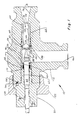
- Valve 10 of the present invention as illustrated is generally called an adjustable choke which is designed to reduce the pressure of the stream flowing therethrough and as a result the valve member and valve seat are subjected to high velocity fluids.
- the improved valve 10 includes body 12 having valve chamber 14, inlet 16 into chamber 14 and outlet 18 from chamber 14.
- Bonnet 20 is secured to body 12 by nut 22 and includes tubular projection 24 extending through valve chamber 14.
- Alignment pin 26 is positioned in opening 28 in body 12 and is adapted to be received in opening 30 in bonnet 20to align bonnet 20 so that port 32 in tubular projection 24 registers with inlet 16.
- Valve seat insert 34 is releasably secured to tubular projection 24 by suitable means such as pins 36 positioned in windows 38 in projecton 24 and held in groove 40 in insert 34 by resilient ring 42.
- Resilient ring 42 is positioned in second groove 43 and is shown as an O-ring but may be any other type of resilient ring to retain pins 36 in groove 40.
- Valve seat insert 34 includes sleeve 44 with blast tube 46 secured within sleeve 44 by suitable means such as silver solder.
- Blasttube 46 is preferably made of a material such as tungsten carbide or silicon carbide which is highly resistant to the erosive action of a high velocity fluid stream flowing therethrough. When installed with projection 24 valve seat insert 34 is positioned in bore 48 of outlet 18 against shoulder 50.
- Bore 54 of outlet 18 is a continuation of bore 52 of blast tube 46 immediately outward of shoulder 50.
- the outer portion of outlet 18 diverges at 56 as shown.
- Tubular projection 24 is sealed in counterbore 55 of valve chamber 14 by resilient seals 57.
- Valve seat insert 34 is sealed in counterbore 49 of valve chamber 14 by resilient seals 51.
- Valve member 58 in the form of a tapered plug is positioned within tubular projection 24 and is adapted to coact with the convergent inlet 60 of blast tube 46 to control the flow through valve 10.
- Valve member 58 is connected to stem 62 by suitable means such as silver solder and is operated by a handwheel (not shown).
- Seal 64 is positioned between stem 62 and the interior surface 63 of tubular projection 24 to effectively seal about the exterior surface 65 of stem 62.
- valve seat insert 34 is to be inspected for wear or replaced, bonnet 20 is removed from body 12 by unthreading nut 22 and sliding bonnet 20 with integral tubular projection 24 and valve insert 34, which is secured to projection 24 by pins 36, out of body 12. Then resilient ring 42 is removed from engagement with the exterior of pins 36. Pins 36 are then withdrawn from groove 40 and valve seat insert 34 is removed from the end of tubular projection 24. A new valve seat insert 34 can then be inserted into tubular projection 24 and pins 36 installed and retained by ring 42 to latch insert 34 into tubular projection 24.
Landscapes
- General Engineering & Computer Science (AREA)
- Engineering & Computer Science (AREA)
- Mechanical Engineering (AREA)
- Magnetically Actuated Valves (AREA)
- Sliding Valves (AREA)
- Temperature-Responsive Valves (AREA)
- Electrically Driven Valve-Operating Means (AREA)
- Sawing (AREA)
- Thermotherapy And Cooling Therapy Devices (AREA)
- Self-Closing Valves And Venting Or Aerating Valves (AREA)
- Lift Valve (AREA)
- Valve Housings (AREA)
- Means For Warming Up And Starting Carburetors (AREA)
Abstract
Description
- Prior valves, such as chokes (for instance US-A-4337788), used to control high velocity flow which is damaging to the valve seat have utilized a replaceable valve seat insert including a blast tube which has generally been threaded into the body in the outlet. When such valves have been used they have been subject to wear and the valve seat insert is difficult to remove and replace since the head of the insert is subject to wear and may not be easily engaged and sometimes is extremely difficult to remove.
- In one prior choke the bonnet is provided with a tubular projection extending into the body chamber and into the body outlet with the inlet extending into the tubular projection. Cam actuated pins are used to engage the tubular projection to retain the bonnet in the body. The valve member and seat include a pair of discs with openings therein which can register or be restricted by rotation of the valving disc. The seat disc rests on a shoulder positioned in the bore of the tubular member. Another prior choke is shown in European Petroleum Conference Paper EUR 370 "New Subsea Choke and Choke Calibration System" as presented at the European Petroleum Conference in London, England in October 1982. This choke uses locking dogs to engage the tubular projection to retain the bonnet in the body. This choke also uses a pair of discs which rotate relative to each other to open or restrict the flow area. Such structures do not include a tapered plug valve member and an annular valve seat, both of which are of a material which is resistant to the erosion of high velocity fluid flow and are removable as a unit.
- The present invention provides an improved valve such as an angle choke having a body having an inlet, a valve chamber and an outlet, a bonnet secured to the body covering the opening into the valve chamber and aligned with the outlet, the bonnet having a tubular projection extending into the outlet, a valve seat insert having a blast tube therein and means for releasably securing the valve seat insert to the bonnet tubular projection, a valve gate member movably mounted in the bonnet to coact with the blast tube to control flow through the valve.
- An object of the present invention is to provide an improved valve, such as a choke, having an easily replaceable valve seat insert.
- Another object is to provide an improved valve with a valve seat insert which is removable independent of the wear it has been subjected to by the flow therethrough.
- These and other objects and advantages are hereinafter set forth and explained with respect to the drawings wherein:
- FIGURE 1 is a sectional view of the improved valve of the present invention.
- FIGURE 2 is an enlarged partial sectional viewto illustrate the valve seat insert and its engagement with the tubular projection of the bonnet.
- FIGURE 3 is a sectional view similarto FIGURE 1 but with the bonnet released from the body and being partially withdrawn from the body with the valve seat insert in the bonnet's tubular projection.
-
Valve 10 of the present invention as illustrated is generally called an adjustable choke which is designed to reduce the pressure of the stream flowing therethrough and as a result the valve member and valve seat are subjected to high velocity fluids. - As shown in FIGURE 1 the improved
valve 10 includesbody 12 havingvalve chamber 14,inlet 16 intochamber 14 andoutlet 18 fromchamber 14.Bonnet 20 is secured tobody 12 bynut 22 and includestubular projection 24 extending throughvalve chamber 14.Alignment pin 26 is positioned in opening 28 inbody 12 and is adapted to be received in opening 30 in bonnet 20to alignbonnet 20 so thatport 32 intubular projection 24 registers withinlet 16. -
Valve seat insert 34 is releasably secured totubular projection 24 by suitable means such aspins 36 positioned inwindows 38 inprojecton 24 and held ingroove 40 ininsert 34 byresilient ring 42.Resilient ring 42 is positioned insecond groove 43 and is shown as an O-ring but may be any other type of resilient ring to retainpins 36 ingroove 40.Valve seat insert 34 includessleeve 44 withblast tube 46 secured withinsleeve 44 by suitable means such as silver solder. Blasttube 46 is preferably made of a material such as tungsten carbide or silicon carbide which is highly resistant to the erosive action of a high velocity fluid stream flowing therethrough. When installed withprojection 24valve seat insert 34 is positioned inbore 48 ofoutlet 18 againstshoulder 50.Bore 54 ofoutlet 18 is a continuation ofbore 52 ofblast tube 46 immediately outward ofshoulder 50. The outer portion ofoutlet 18 diverges at 56 as shown.Tubular projection 24 is sealed incounterbore 55 ofvalve chamber 14 byresilient seals 57.Valve seat insert 34 is sealed incounterbore 49 ofvalve chamber 14 byresilient seals 51. - Valve
member 58 in the form of a tapered plug is positioned withintubular projection 24 and is adapted to coact with theconvergent inlet 60 ofblast tube 46 to control the flow throughvalve 10. Valvemember 58 is connected tostem 62 by suitable means such as silver solder and is operated by a handwheel (not shown).Seal 64 is positioned betweenstem 62 and theinterior surface 63 oftubular projection 24 to effectively seal about theexterior surface 65 ofstem 62. - Rotation of the handwheel causes
stem 62, which is threadly connected inbonnet 20 by threads, to rotate which causesplug 58 to move toward or away frominlet 60 ofblast tube 46 to control the flow throughvalve 10 from the fully opened position of FIGURE 1 to the fully closed position of FIGURE 2. Whenevervalve seat insert 34 is to be inspected for wear or replaced,bonnet 20 is removed frombody 12 byunthreading nut 22 and slidingbonnet 20 with integraltubular projection 24 andvalve insert 34, which is secured toprojection 24 bypins 36, out ofbody 12. Thenresilient ring 42 is removed from engagement with the exterior ofpins 36.Pins 36 are then withdrawn fromgroove 40 andvalve seat insert 34 is removed from the end oftubular projection 24. A newvalve seat insert 34 can then be inserted intotubular projection 24 andpins 36 installed and retained byring 42 to latch insert 34 intotubular projection 24.
Claims (6)
Priority Applications (1)
| Application Number | Priority Date | Filing Date | Title |
|---|---|---|---|
| AT84301843T ATE31210T1 (en) | 1983-04-29 | 1984-03-19 | VALVE. |
Applications Claiming Priority (2)
| Application Number | Priority Date | Filing Date | Title |
|---|---|---|---|
| US06/490,183 US4503878A (en) | 1983-04-29 | 1983-04-29 | Choke valve |
| US490183 | 1983-04-29 |
Publications (3)
| Publication Number | Publication Date |
|---|---|
| EP0124230A2 EP0124230A2 (en) | 1984-11-07 |
| EP0124230A3 EP0124230A3 (en) | 1985-07-24 |
| EP0124230B1 true EP0124230B1 (en) | 1987-12-02 |
Family
ID=23946943
Family Applications (1)
| Application Number | Title | Priority Date | Filing Date |
|---|---|---|---|
| EP84301843A Expired EP0124230B1 (en) | 1983-04-29 | 1984-03-19 | Valve |
Country Status (9)
| Country | Link |
|---|---|
| US (1) | US4503878A (en) |
| EP (1) | EP0124230B1 (en) |
| JP (1) | JPS59208275A (en) |
| AT (1) | ATE31210T1 (en) |
| CA (1) | CA1227178A (en) |
| DE (1) | DE3467917D1 (en) |
| MX (1) | MX159434A (en) |
| NO (1) | NO158113C (en) |
| SG (1) | SG29588G (en) |
Families Citing this family (36)
| Publication number | Priority date | Publication date | Assignee | Title |
|---|---|---|---|---|
| US4774980A (en) * | 1985-10-03 | 1988-10-04 | Etheridge Reggie H | Piloted wellhead flow control valve |
| US4662603A (en) * | 1985-10-03 | 1987-05-05 | Seaboard Wellhead, Inc. | Piloted wellhead flow control valve |
| DE3702063C1 (en) * | 1987-01-24 | 1988-11-17 | B & S Metalpraecis Gmbh | Shut-off and control valve for corrosive media, especially for moist chlorine-containing gases and fluids containing chlorine ions |
| US4735229A (en) * | 1987-05-01 | 1988-04-05 | Varco/Best Flow Products | Wear monitoring construction for erosive/corrosive flow conducting devices |
| JPH0792159B2 (en) * | 1987-12-09 | 1995-10-09 | 株式会社日立製作所 | Gas governor equipment |
| US4848473A (en) * | 1987-12-21 | 1989-07-18 | Chevron Research Company | Subsea well choke system |
| US5255700A (en) * | 1988-08-08 | 1993-10-26 | Pneu-Draulics, Inc. | Capacity fuse valve |
| US4834133A (en) * | 1988-09-28 | 1989-05-30 | Westinghouse Electric Corp. | Control valve |
| US5050633A (en) * | 1989-06-19 | 1991-09-24 | Emhart Inc. | Fluid valve |
| US5074519A (en) * | 1990-11-09 | 1991-12-24 | Cooper Industries, Inc. | Fail-close hydraulically actuated control choke |
| US5065787A (en) * | 1991-05-03 | 1991-11-19 | Fmc Corporation | Choke valve safety device |
| EP0520566B1 (en) * | 1991-06-24 | 1996-03-13 | NORSK HYDRO a.s. | Valve device having stationary and movable or turnable valve bodies |
| US5368273A (en) * | 1992-10-21 | 1994-11-29 | Allied Signal Inc. | Venturi metering system |
| US6276386B1 (en) * | 1997-11-24 | 2001-08-21 | Kvaerner Oilfield Products, Inc. | Charging device for hydraulic systems |
| AT410405B (en) * | 2001-09-17 | 2003-04-25 | Andritz Ag Maschf | METHOD AND DEVICE FOR SEPARATING INTERFERENTS FROM SUSPENSIONS BY FLOTATION |
| US6695000B2 (en) * | 2001-11-15 | 2004-02-24 | Fisher Controls International Llc | Control valve pressure bleed inspection port |
| US7025140B2 (en) * | 2003-01-16 | 2006-04-11 | Mcgee Richard Harvey | Large particulate removal system |
| USRE42772E1 (en) | 2003-01-16 | 2011-10-04 | Stinger Wellhead Protection, Inc. | Large particulate removal system |
| DE602004019212D1 (en) * | 2003-05-31 | 2009-03-12 | Cameron Systems Ireland Ltd | DEVICE AND METHOD FOR RECOVERING UNDERGROUND LIQUIDS AND / OR INJECTING LIQUIDS IN A DRILLING HOLE |
| AU2005216412B2 (en) | 2004-02-26 | 2011-03-31 | Onesubsea Ip Uk Limited | Connection system for subsea flow interface equipment |
| ATE527483T1 (en) * | 2004-05-13 | 2011-10-15 | Caldera Engineering L C | MULTIPHASE NOZZLE WITH CONTROLLED DISPERSION AND PRODUCTION METHOD THEREOF |
| US7363937B2 (en) * | 2004-07-16 | 2008-04-29 | M-I L.L.C. | Replaceable sleeve insert for a choke assembly |
| US7004448B2 (en) * | 2004-07-19 | 2006-02-28 | M-I Llc | Trim insert for choke assembly |
| GB0618001D0 (en) * | 2006-09-13 | 2006-10-18 | Des Enhanced Recovery Ltd | Method |
| US8051874B2 (en) | 2006-09-13 | 2011-11-08 | Fisher Controls International Llc | Replaceable outlet liner for control valve |
| GB0625526D0 (en) | 2006-12-18 | 2007-01-31 | Des Enhanced Recovery Ltd | Apparatus and method |
| GB0625191D0 (en) * | 2006-12-18 | 2007-01-24 | Des Enhanced Recovery Ltd | Apparatus and method |
| US8006715B2 (en) * | 2007-09-20 | 2011-08-30 | Caterpillar Inc. | Valve with thin-film coating |
| WO2011088548A1 (en) * | 2010-01-22 | 2011-07-28 | Master Flo Valve Inc. | Cage valve with flow trim for reduced fracturing |
| US20110226980A1 (en) * | 2010-03-19 | 2011-09-22 | Richardson Jonathan W | Valves having ceramic trim with protected shut-off surfaces |
| DE102013010027A1 (en) * | 2013-06-17 | 2014-12-18 | Otto Egelhof Gmbh & Co. Kg | Drive device and method for controlling the drive means for generating an actuating movement |
| US10125875B2 (en) * | 2016-05-31 | 2018-11-13 | Cameron International Corporation | Choke plug tip |
| US11125049B2 (en) | 2017-01-23 | 2021-09-21 | Cameron Technologies Limited | Superhard material enhanced choke cage |
| US10830359B2 (en) | 2017-07-31 | 2020-11-10 | Cameron International Corporation | Needle tip and seat for a choke valve |
| US11022228B2 (en) * | 2018-07-10 | 2021-06-01 | Caldera Engineering, Lc | Systems and methods for a plug valve |
| US12259064B2 (en) | 2018-11-01 | 2025-03-25 | Oil States Energy Services, L.L.C. | Valve with pressure differential seating |
Family Cites Families (16)
| Publication number | Priority date | Publication date | Assignee | Title |
|---|---|---|---|---|
| DE1072855B (en) * | 1960-01-07 | Dipl-Ing Hans Weber, Köln | High pressure valve | |
| FR1208863A (en) * | 1957-11-26 | 1960-02-26 | I V Pressure Controllers Ltd | Manually Controlled Fluid Control Valves |
| US3180420A (en) * | 1963-02-11 | 1965-04-27 | Halliburton Co | Retrievable bridging plug for well casings |
| US3204655A (en) * | 1963-02-20 | 1965-09-07 | Crane Co | Disc-stem connection for valves |
| JPS4328538Y1 (en) * | 1965-09-08 | 1968-11-25 | ||
| DE1282379B (en) * | 1965-11-04 | 1968-11-07 | Danfoss As | Valve |
| FR2036280A5 (en) * | 1969-03-12 | 1970-12-24 | Fem Fournit Equip Menager | |
| JPS4830427B1 (en) * | 1970-05-08 | 1973-09-20 | ||
| US3829059A (en) * | 1973-06-08 | 1974-08-13 | Dial Ind Inc | Automatic valve adapter |
| DE2359174A1 (en) * | 1973-11-28 | 1975-06-12 | Bundesrep Deutschland | Oxy-acetylene hose detachable bayonet coupling - has automatic gas seal by O-rings locked in position by sprung detent |
| US4128109A (en) * | 1975-12-30 | 1978-12-05 | Hydrocarbon Research, Inc. | Pressure let-down valve assembly for handling abrasive liquids |
| GB1561159A (en) * | 1978-03-13 | 1980-02-13 | Bvmi Ltd | Fluid control valves |
| DE8012995U1 (en) * | 1980-05-13 | 1980-09-18 | Samson Ag, 6000 Frankfurt | WEAR-RESISTANT FITTING FOR FLOWING SUBSTANCES |
| US4336824A (en) * | 1980-05-29 | 1982-06-29 | United Aircraft Products, Inc. | Cartridge valve |
| US4337788A (en) * | 1981-02-02 | 1982-07-06 | Smith International Inc. | High pressure valve |
| US4413646A (en) * | 1981-05-01 | 1983-11-08 | Exxon Research And Engineering Co. | Streamline coal slurry letdown valve |
-
1983
- 1983-04-29 US US06/490,183 patent/US4503878A/en not_active Expired - Fee Related
-
1984
- 1984-03-19 DE DE8484301843T patent/DE3467917D1/en not_active Expired
- 1984-03-19 EP EP84301843A patent/EP0124230B1/en not_active Expired
- 1984-03-19 AT AT84301843T patent/ATE31210T1/en not_active IP Right Cessation
- 1984-03-22 CA CA000450190A patent/CA1227178A/en not_active Expired
- 1984-04-03 MX MX200903A patent/MX159434A/en unknown
- 1984-04-27 NO NO84841679A patent/NO158113C/en unknown
- 1984-04-27 JP JP59086004A patent/JPS59208275A/en active Pending
-
1988
- 1988-05-05 SG SG295/88A patent/SG29588G/en unknown
Non-Patent Citations (1)
| Title |
|---|
| European Petroleum Conference Paper, EUR.370 "New Subsea Choke and Choke Calibration System", England, October 1982 * |
Also Published As
| Publication number | Publication date |
|---|---|
| NO158113B (en) | 1988-04-05 |
| JPS59208275A (en) | 1984-11-26 |
| NO158113C (en) | 1988-07-13 |
| CA1227178A (en) | 1987-09-22 |
| MX159434A (en) | 1989-06-01 |
| NO841679L (en) | 1984-10-30 |
| SG29588G (en) | 1988-09-30 |
| EP0124230A2 (en) | 1984-11-07 |
| ATE31210T1 (en) | 1987-12-15 |
| DE3467917D1 (en) | 1988-01-14 |
| US4503878A (en) | 1985-03-12 |
| EP0124230A3 (en) | 1985-07-24 |
Similar Documents
| Publication | Publication Date | Title |
|---|---|---|
| US4503878A (en) | Choke valve | |
| US4446887A (en) | Variable high pressure choke | |
| US4478286A (en) | Equalizing valve for subterranean wells | |
| US3521853A (en) | Throttle and shutoff valve | |
| US5732731A (en) | Secondary seal bypass valve for gate valves | |
| US8371333B2 (en) | Cage valve with erosion control | |
| US3035808A (en) | Pressure responsive valve | |
| US3761052A (en) | Flow plugger valve | |
| US5004007A (en) | Chemical injection valve | |
| US4220176A (en) | Methods and apparatus for controlling fluid flow | |
| US4461316A (en) | Drilling choke | |
| US4874007A (en) | Restrictor valve flow passage pop-up wear indicator | |
| GB2124341A (en) | Fluid flow choke | |
| US4190073A (en) | Choke for controlling the flow of drilling mud | |
| US10927964B2 (en) | Self-cleaning double block and bleed valve | |
| GB2462879A (en) | A choke valve with erosion control mechanism | |
| US2854998A (en) | Air tank charging valve | |
| GB2198767A (en) | - Variable fluid passageway for a well tool | |
| US3075589A (en) | Dual passage drilling stem having selfcontained valve means | |
| US4531545A (en) | Drilling choke valve | |
| US5370155A (en) | Wedge-type gate valve | |
| US3171440A (en) | Bleeder valve | |
| US6446664B1 (en) | Erosion resistant wear sleeve for high pressure valves | |
| US4337807A (en) | High pressure coupling | |
| US4176679A (en) | Check valve |
Legal Events
| Date | Code | Title | Description |
|---|---|---|---|
| PUAI | Public reference made under article 153(3) epc to a published international application that has entered the european phase |
Free format text: ORIGINAL CODE: 0009012 |
|
| AK | Designated contracting states |
Designated state(s): AT BE CH DE FR GB IT LI LU NL SE |
|
| PUAL | Search report despatched |
Free format text: ORIGINAL CODE: 0009013 |
|
| AK | Designated contracting states |
Designated state(s): AT BE CH DE FR GB IT LI LU NL SE |
|
| 17P | Request for examination filed |
Effective date: 19851025 |
|
| 17Q | First examination report despatched |
Effective date: 19870219 |
|
| GRAA | (expected) grant |
Free format text: ORIGINAL CODE: 0009210 |
|
| AK | Designated contracting states |
Kind code of ref document: B1 Designated state(s): AT BE CH DE FR GB IT LI LU NL SE |
|
| PG25 | Lapsed in a contracting state [announced via postgrant information from national office to epo] |
Ref country code: LI Effective date: 19871202 Ref country code: IT Free format text: LAPSE BECAUSE OF FAILURE TO SUBMIT A TRANSLATION OF THE DESCRIPTION OR TO PAY THE FEE WITHIN THE PRESCRIBED TIME-LIMIT;WARNING: LAPSES OF ITALIAN PATENTS WITH EFFECTIVE DATE BEFORE 2007 MAY HAVE OCCURRED AT ANY TIME BEFORE 2007. THE CORRECT EFFECTIVE DATE MAY BE DIFFERENT FROM THE ONE RECORDED. Effective date: 19871202 Ref country code: CH Effective date: 19871202 Ref country code: BE Effective date: 19871202 |
|
| REF | Corresponds to: |
Ref document number: 31210 Country of ref document: AT Date of ref document: 19871215 Kind code of ref document: T |
|
| REF | Corresponds to: |
Ref document number: 3467917 Country of ref document: DE Date of ref document: 19880114 |
|
| ET | Fr: translation filed | ||
| REG | Reference to a national code |
Ref country code: CH Ref legal event code: PL |
|
| PG25 | Lapsed in a contracting state [announced via postgrant information from national office to epo] |
Ref country code: LU Free format text: LAPSE BECAUSE OF NON-PAYMENT OF DUE FEES Effective date: 19880331 |
|
| PLBE | No opposition filed within time limit |
Free format text: ORIGINAL CODE: 0009261 |
|
| STAA | Information on the status of an ep patent application or granted ep patent |
Free format text: STATUS: NO OPPOSITION FILED WITHIN TIME LIMIT |
|
| REG | Reference to a national code |
Ref country code: GB Ref legal event code: 732 |
|
| 26N | No opposition filed | ||
| PGFP | Annual fee paid to national office [announced via postgrant information from national office to epo] |
Ref country code: SE Payment date: 19930219 Year of fee payment: 10 |
|
| PGFP | Annual fee paid to national office [announced via postgrant information from national office to epo] |
Ref country code: NL Payment date: 19930331 Year of fee payment: 10 |
|
| PG25 | Lapsed in a contracting state [announced via postgrant information from national office to epo] |
Ref country code: SE Free format text: LAPSE BECAUSE OF NON-PAYMENT OF DUE FEES Effective date: 19940320 |
|
| PG25 | Lapsed in a contracting state [announced via postgrant information from national office to epo] |
Ref country code: NL Effective date: 19941001 |
|
| NLV4 | Nl: lapsed or anulled due to non-payment of the annual fee | ||
| EUG | Se: european patent has lapsed |
Ref document number: 84301843.3 Effective date: 19941010 |
|
| PGFP | Annual fee paid to national office [announced via postgrant information from national office to epo] |
Ref country code: GB Payment date: 19950208 Year of fee payment: 12 |
|
| PGFP | Annual fee paid to national office [announced via postgrant information from national office to epo] |
Ref country code: AT Payment date: 19950222 Year of fee payment: 12 |
|
| PGFP | Annual fee paid to national office [announced via postgrant information from national office to epo] |
Ref country code: FR Payment date: 19950315 Year of fee payment: 12 |
|
| PGFP | Annual fee paid to national office [announced via postgrant information from national office to epo] |
Ref country code: DE Payment date: 19950328 Year of fee payment: 12 |
|
| REG | Reference to a national code |
Ref country code: GB Ref legal event code: 732E |
|
| PG25 | Lapsed in a contracting state [announced via postgrant information from national office to epo] |
Ref country code: GB Effective date: 19960319 Ref country code: AT Effective date: 19960319 |
|
| GBPC | Gb: european patent ceased through non-payment of renewal fee |
Effective date: 19960319 |
|
| PG25 | Lapsed in a contracting state [announced via postgrant information from national office to epo] |
Ref country code: FR Effective date: 19961129 |
|
| PG25 | Lapsed in a contracting state [announced via postgrant information from national office to epo] |
Ref country code: DE Effective date: 19961203 |
|
| REG | Reference to a national code |
Ref country code: FR Ref legal event code: ST |