EP0123657A1 - Reverser device for agricultural machines, particularly combine harvester - Google Patents
Reverser device for agricultural machines, particularly combine harvester Download PDFInfo
- Publication number
- EP0123657A1 EP0123657A1 EP84830083A EP84830083A EP0123657A1 EP 0123657 A1 EP0123657 A1 EP 0123657A1 EP 84830083 A EP84830083 A EP 84830083A EP 84830083 A EP84830083 A EP 84830083A EP 0123657 A1 EP0123657 A1 EP 0123657A1
- Authority
- EP
- European Patent Office
- Prior art keywords
- shaft
- rotary members
- combine harvester
- produce
- unit
- Prior art date
- Legal status (The legal status is an assumption and is not a legal conclusion. Google has not performed a legal analysis and makes no representation as to the accuracy of the status listed.)
- Withdrawn
Links
- 230000005540 biological transmission Effects 0.000 claims abstract description 31
- 238000003306 harvesting Methods 0.000 claims abstract description 8
- 241000251169 Alopias vulpinus Species 0.000 claims abstract description 5
- 230000000694 effects Effects 0.000 abstract description 3
- 241001124569 Lycaenidae Species 0.000 description 2
- 238000005452 bending Methods 0.000 description 1
- 238000004140 cleaning Methods 0.000 description 1
Images

Classifications
-
- A—HUMAN NECESSITIES
- A01—AGRICULTURE; FORESTRY; ANIMAL HUSBANDRY; HUNTING; TRAPPING; FISHING
- A01D—HARVESTING; MOWING
- A01D41/00—Combines, i.e. harvesters or mowers combined with threshing devices
- A01D41/12—Details of combines
- A01D41/14—Mowing tables
- A01D41/142—Header drives
-
- A—HUMAN NECESSITIES
- A01—AGRICULTURE; FORESTRY; ANIMAL HUSBANDRY; HUNTING; TRAPPING; FISHING
- A01D—HARVESTING; MOWING
- A01D69/00—Driving mechanisms or parts thereof for harvesters or mowers
Definitions
- the present invention relates to agricultural machines, particularly combine harvesters, of the known type comprising:
- the object of the present invention is to avoid these disadvantages.
- the main characteristic of the machine according to the invention lies in the fact that the reverser means comprise an auxiliary drive transmission which can be engaged when a blockage occurs to connect the rotary members of the front unit of the machine to a continuously rotating shaft forming part of the produce treatment unit.
- the rotating shaft used to drive the reverse movement of the members of the front unit of the machine through the auxiliary transmission is preferably constituted by the shaft of the threshing cylinder of the thresher unit.
- this shaft has one end-projecting from the side of the machine, which lends itself to use for the said purpose and enables the assembly of the auxiliary drive transmission by simple and economical operations.
- Figure 1 illustrates schematically a combine harvester of conventional type having a front unit 1 for harvesting the produce and a thresher unit 2.
- the front unit 1 includes a cutting platform 1a having a cutter bar 3, a reel 4 arranged to facilitate the introduction of the produce to the cutting platform la, a feed screw 5, and a bar elevator device 6 which receives the produce from the feed screw 5 and feeds it to the threshing apparatus.
- the shaft 7 located in correspondence with the discharge end of the bar elevator 6 can also be used as the shaft for articulating the cutting platform la to the chassis of the harvester, the platform la being raisable by means of actuators 8.
- FIG 2 there is shown a drive transmission, generally indicated 9, disposed on the left-hand side of the harvester, which takes drive from an engine 10 and drives all the rotary members of the front unit 1, the thresher unit 2, and the cleaning unit 11.
- Figure 3 illustrates that part of the drive transmission 9 which is located on the right-hand side of the harvester.
- All the members of the front unit 1 of the harvester are connected together by a driving chain 12 which terminates at a pulley 13 mounted on the shaft 7 of the elevator 6.
- the pulley 13 is connected to the drive transmission 9 of the harvester by means of a belt drive 14 which can be disengaged by a control from the driving position 15.
- the drive 14 connects the pulley 13 to a pulley 16 driven by the engine 10.
- the engagement ana disengagement of the belt drive 14 may be achieved, in known manner, by the operation of a belt stretcher 17 or by an electromagnetic or mechanical friction clutch of known type (not shown) located in correspondence with the pulley 16.
- the combine harvester includes a reverser device 18 which includes an auxiliary drive transmission 19 for driving the rotation of the members of the front unit 1 in the opposite sense from that of normal operation.
- the transmission 19 includes a belt 20 which engages a pulley wheel 21 coaxial with the pulley 13 and a freely rotatable pulley 22 carried by a lever 23 articulated to one end of a lever 24 the opposite end of which is articulated, in its turn, to the chassis of the harvester at 25.
- a spring 26 interposed between the levers 23, 24 keeps the belt 20 always under tension.
- the driving position has a control lever 27 connected through a cable 28 to the lever 24.
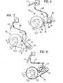
- a control lever 27 By operating the lever 27, the operator can effect the movement of the transmission 19 between the operative condition illustrated in Figure 4 and the inoperative condition illustrated in Figure 5.
- the device illustrated above has obvious advantages of simplicity and economy, may easily be adapted to a machine lacking a reverser device to begin with, and also allows gradual operation of the reversal phase.
- the operator may in fact operate the lever 27 so as to cause a measured and controlled bringing together of the belt 20 and the pulley wheel 29 to avoid a violent reversal.
- the belt 20 engages the groove in the pulley 29 progressively and may, at the limit, slip relative to the pulley.
- the outer side of the belt 20 engages the pulley wheel 29 to allow the reversal of movement.
- the pulley wheel 21 has a much larger diameter than the diameter of the pulley wheel 29 to enable a reversing couple to be achieved on the shaft 7 (Figure 1) which is sufficient to overcome easily any braking torque applied to the various members.
- the embodiment illustrated in Figure 6 differs from that of Figures 4, 5 in that the transmission 19 is constituted by a chain transmission, the inner side of which engages a gear wheel 30 carried by the shaft 7 ( Figure 1) and a gear wheel 31 freely rotatably mounted on the chassis of the harvester, and the outer side of which engages a gear wheel 32 which can be connected to the shaft of the threshing cylinder 2a ( Figure 1) by a friction clutch of conventional type (the structure of which is not shown in detail) driven by a transmission 33 connected to the control lever 27.
- a friction clutch of conventional type the structure of which is not shown in detail
Abstract
An agricultural machine, particularly a combine harvester, comprises a front unit (1) for harvesting the produce and a produce treatment unit (2), which include a series of rotary members (4, 5, 6, 2a), and a transmission (9) for driving the rotary members. The machine has means for disconnecting the connection between the drive transmission (9) and the rotary members ofthe front unit (1) for harvesting the produce when the latter jams as a result of a blockage by the produce. Reverser means (18) are provided for rotating the rotary members of the front harvesting unit (1) in the opposite sense from that of its normal operation in orderto expel the material which has caused the blockage. According to the invention, these reverser means (18) include an auxiliary drive transmission (19) which can be engaged when a blockage occurs to connect the rotary members of the front unit (1) of the machine to a continuously rotating shaft (29) forming part of the produce treatment unit (2). In the case of a combine harvester, the rotating shaft (29) used to effect this opposite rotation is the shaft of the threshing cylinder (2a) of the thresher unit (2).
Description
- The present invention relates to agricultural machines, particularly combine harvesters, of the known type comprising:
- a front unit for harvesting the produce and a produce treatment unit, including a series of rotary members,
- a drive transmission for th.e rotary members,
- means for disconnecting the connection between the drive transmission and the rotary members of the front harvesting unit, and
- reverser means for rotating the rotary members of the front unit of the machine in the opposite sense from that of normal operation.in order to expel the material and free the rotary members in the event of a blockage by the produce.
- Various types of reverser devices have already been proposed for allowing the rotary members of the produce harvesting unit to be freed in the event of a blockage without necessitating the stoppage of the machine and direct intervention by the operator.
- These known solutions, however, have the disadvantages of being relatively complicated and expensive, of not being easily adaptable to a machine lacking a reverser to begin with, and, above all, of involving a sudden and violent reversing operation which often causes damage to the transmissions (breakage of chains, bending of shafts, etc.).
- The object of the present invention is to avoid these disadvantages.
- The main characteristic of the machine according to the invention lies in the fact that the reverser means comprise an auxiliary drive transmission which can be engaged when a blockage occurs to connect the rotary members of the front unit of the machine to a continuously rotating shaft forming part of the produce treatment unit.
- In the case of a combine harvester, the rotating shaft used to drive the reverse movement of the members of the front unit of the machine through the auxiliary transmission is preferably constituted by the shaft of the threshing cylinder of the thresher unit. Indeed,in conventional combine harvesters,this shaft has one end-projecting from the side of the machine, which lends itself to use for the said purpose and enables the assembly of the auxiliary drive transmission by simple and economical operations.
- Further characteristics and advantages of the invention will become apparent from the description which follows with reference to the appended drawings, provided purely by way of non-limiting example, in which:
- Figure 1 is a schematic side view of a combine harvester,
- Figures 2, 3 are side views showing the drive transmission disposed on the two sides of the combine harvester,
- Figures 4, 5 illustrate a first embodiment of the reverser device according to the invention in two different conditions of operation, and
- Figure 6 illustrates a second embodiment of the reverser device.
- Figure 1 illustrates schematically a combine harvester of conventional type having a front unit 1 for harvesting the produce and a
thresher unit 2. The front unit 1 includes acutting platform 1a having acutter bar 3, a reel 4 arranged to facilitate the introduction of the produce to the cutting platform la,a feed screw 5, and abar elevator device 6 which receives the produce from the feed screw 5 and feeds it to the threshing apparatus. Theshaft 7 located in correspondence with the discharge end of thebar elevator 6 can also be used as the shaft for articulating the cutting platform la to the chassis of the harvester, the platform la being raisable by means ofactuators 8. - In Figure 2, there is shown a drive transmission, generally indicated 9, disposed on the left-hand side of the harvester, which takes drive from an
engine 10 and drives all the rotary members of the front unit 1, thethresher unit 2, and thecleaning unit 11. - Figure 3 illustrates that part of the drive transmission 9 which is located on the right-hand side of the harvester.
- All the members of the front unit 1 of the harvester are connected together by a
driving chain 12 which terminates at apulley 13 mounted on theshaft 7 of theelevator 6. - The
pulley 13 is connected to the drive transmission 9 of the harvester by means of a belt drive 14 which can be disengaged by a control from thedriving position 15. The drive 14 connects thepulley 13 to apulley 16 driven by theengine 10. The engagement ana disengagement of the belt drive 14 may be achieved, in known manner, by the operation of abelt stretcher 17 or by an electromagnetic or mechanical friction clutch of known type (not shown) located in correspondence with thepulley 16. - In the embodiment illustrated in Figures 4, 5 the combine harvester includes a
reverser device 18 which includes anauxiliary drive transmission 19 for driving the rotation of the members of the front unit 1 in the opposite sense from that of normal operation. Thetransmission 19 includes a belt 20 which engages a pulley wheel 21 coaxial with thepulley 13 and a freelyrotatable pulley 22 carried by alever 23 articulated to one end of alever 24 the opposite end of which is articulated, in its turn, to the chassis of the harvester at 25. Aspring 26 interposed between thelevers - The driving position has a
control lever 27 connected through acable 28 to thelever 24. By operating thelever 27, the operator can effect the movement of thetransmission 19 between the operative condition illustrated in Figure 4 and the inoperative condition illustrated in Figure 5. - In the operative condition, the outer side of the belt 20 comes into contact with a
pulley wheel 29 mounted on the end of the shaft of the threshingcylinder 2a (see Figure 1)which projects from the left-hand side of the harvester. - When the members of the front unit of the harvester jam as a result of a blockage by the produce, the transmission 14 (Figure 2)is disengaged in order to break the connection between the rotary members and the drive transmission 9 (Figure 2) of the harvester. At this point, the operator operates the lever 27 (see Figures 4, 5) so as to bring the
transmission 19 into the operative condition illustrated in Figure 4 and effect the movement of the members of the unit 1 of the harvester in the opposite sense to expel the material which has caused the jamming of these members. - The device illustrated above has obvious advantages of simplicity and economy, may easily be adapted to a machine lacking a reverser device to begin with, and also allows gradual operation of the reversal phase. The operator may in fact operate the
lever 27 so as to cause a measured and controlled bringing together of the belt 20 and thepulley wheel 29 to avoid a violent reversal. Thus, there is no risk of two sharp,harmful blows to the transmission, by virtue of the fact that the belt 20 engages the groove in thepulley 29 progressively and may, at the limit, slip relative to the pulley. - The outer side of the belt 20 engages the
pulley wheel 29 to allow the reversal of movement. - The pulley wheel 21 has a much larger diameter than the diameter of the
pulley wheel 29 to enable a reversing couple to be achieved on the shaft 7 (Figure 1) which is sufficient to overcome easily any braking torque applied to the various members. - The embodiment illustrated in Figure 6 differs from that of Figures 4, 5 in that the
transmission 19 is constituted by a chain transmission, the inner side of which engages agear wheel 30 carried by the shaft 7 (Figure 1) and agear wheel 31 freely rotatably mounted on the chassis of the harvester, and the outer side of which engages agear wheel 32 which can be connected to the shaft of thethreshing cylinder 2a (Figure 1) by a friction clutch of conventional type (the structure of which is not shown in detail) driven by atransmission 33 connected to thecontrol lever 27.
Claims (7)
1. Agricultural machine, particularly a combine harvester, including:
a front unit (1)for harvesting the produce and a produce treatment unit (2), including a series of rotary members (4, 5, 6, 2a),
a drive transmission (9) for the rotary members,
means (14) for disconnecting the connection between the drive transmission (9) and the rotary members of the front unit (1), and
reverser means for rotating the rotary members of the front unit (1) of the machine in the opposite sense from that of normal operation in order to expel material and free the rotary members in the event of a blockage by the produce,
characterised in that the reverser means comprise an auxiliary drive transmission (19) which can be engaged when the blockage occurs to connect the rotary members of the front unit (1) of the machine to a continuously rotating shaft (29) forming part of the produce treatment unit (2).
2. Combine harvester according to Claim 1, characterised in that the rotating shaft is the shaft of the threshing cylinder (2a) forming part of the thresher unit of the harvester.
3. Combine harvester according to Claim 2, in which the combine harvester includes a front unit having an elevator device (6), characterised in that the rotary members of this front unit (1) are connected together by a driving chain (12) which terminates at a shaft (7) located in correspondence with the discharge end of the elevator device (6), and in that this shaft (7) is connected to the drive transmission (9) of the harvester through a belt drive (14) which can be disengaged by a control from the driving position.
4. Combine harvester according to Claim 3, characterised in that the shaft 7 of the elevator device (6) also carries a wheel (21) connected by means of the auxiliary disengageable transmission (19) to the shaft of the threshing cylinder (2a).
5. Combine harvester according to Claim 4, characterised in that the auxiliary transmission (19) includes a belt transmission movable between an operative position in which the outer side (20) of the belt is in contact with a wheel (29) carried by the shaft of the threshing cylinder (2a), and an inoperative position in which the belt (20) is spaced from the wheel (29) carried by the shaft of the threshing cylinder (2a).
6. Combine harvester according to Claim 4, characterised in that the auxiliary transmission (19) is constituted by a chain drive the outer side of which engages a gear wheel (32)mounted on the shaft of the threshing cylinder (2a) and connectible to this shaft by means of a clutch device.
7. Combine harvester according to Claim 5 or Claim 6, characterised in that the wheel (13, 21, 30) mounted on the shaft (7) of the elevator device (6) has a considerably larger diameter than the wheel (29) mounted on the shaft of the threshing cylinder (2a).
Applications Claiming Priority (2)
| Application Number | Priority Date | Filing Date | Title |
|---|---|---|---|
| IT67452/83A IT1159566B (en) | 1983-04-26 | 1983-04-26 | REVERSE DEVICE FOR AGRICULTURAL MACHINES PARTICULARLY COMBINE HARVESTERS |
| IT6745283 | 1983-04-26 |
Publications (1)
| Publication Number | Publication Date |
|---|---|
| EP0123657A1 true EP0123657A1 (en) | 1984-10-31 |
Family
ID=11302498
Family Applications (1)
| Application Number | Title | Priority Date | Filing Date |
|---|---|---|---|
| EP84830083A Withdrawn EP0123657A1 (en) | 1983-04-26 | 1984-03-23 | Reverser device for agricultural machines, particularly combine harvester |
Country Status (2)
| Country | Link |
|---|---|
| EP (1) | EP0123657A1 (en) |
| IT (1) | IT1159566B (en) |
Cited By (2)
| Publication number | Priority date | Publication date | Assignee | Title |
|---|---|---|---|---|
| EP0986946A3 (en) * | 1994-05-07 | 2000-04-26 | New Holland Belgium N.V. | Drive line configuration for a harvesting machine |
| CN112930844A (en) * | 2019-12-11 | 2021-06-11 | 迪尔公司 | Harvester gap bridge reverse rotation control device and harvester |
Citations (7)
| Publication number | Priority date | Publication date | Assignee | Title |
|---|---|---|---|---|
| US3334522A (en) * | 1965-06-14 | 1967-08-08 | Toffin Nicholas | Forward and reverse mechanism for self-propelled agricultural implements and the like |
| DE2410462A1 (en) * | 1973-03-09 | 1974-09-19 | Laverda Spa Pietro | FORAGE HARVEST |
| US4038880A (en) * | 1975-10-30 | 1977-08-02 | Hesston Corporation | Drive train and transmission for forage harvester |
| US4046022A (en) * | 1976-06-09 | 1977-09-06 | Dayco Corporation | Belt drive system |
| FR2373002A1 (en) * | 1976-12-02 | 1978-06-30 | Stafor | RELEASEABLE FRONT AND REAR STEP TRANSMISSION DEVICE |
| GB2024963A (en) * | 1978-07-03 | 1980-01-16 | Sperry Rand Nv | Harvesting machines |
| DE3014914A1 (en) * | 1980-04-18 | 1981-10-22 | Claas Ohg, 4834 Harsewinkel | DEVICE FOR REVERSING THE DRIVE SYSTEM OF THE PULL-IN ORGANS OF A COMBINE HARVEST |
-
1983
- 1983-04-26 IT IT67452/83A patent/IT1159566B/en active
-
1984
- 1984-03-23 EP EP84830083A patent/EP0123657A1/en not_active Withdrawn
Patent Citations (7)
| Publication number | Priority date | Publication date | Assignee | Title |
|---|---|---|---|---|
| US3334522A (en) * | 1965-06-14 | 1967-08-08 | Toffin Nicholas | Forward and reverse mechanism for self-propelled agricultural implements and the like |
| DE2410462A1 (en) * | 1973-03-09 | 1974-09-19 | Laverda Spa Pietro | FORAGE HARVEST |
| US4038880A (en) * | 1975-10-30 | 1977-08-02 | Hesston Corporation | Drive train and transmission for forage harvester |
| US4046022A (en) * | 1976-06-09 | 1977-09-06 | Dayco Corporation | Belt drive system |
| FR2373002A1 (en) * | 1976-12-02 | 1978-06-30 | Stafor | RELEASEABLE FRONT AND REAR STEP TRANSMISSION DEVICE |
| GB2024963A (en) * | 1978-07-03 | 1980-01-16 | Sperry Rand Nv | Harvesting machines |
| DE3014914A1 (en) * | 1980-04-18 | 1981-10-22 | Claas Ohg, 4834 Harsewinkel | DEVICE FOR REVERSING THE DRIVE SYSTEM OF THE PULL-IN ORGANS OF A COMBINE HARVEST |
Cited By (3)
| Publication number | Priority date | Publication date | Assignee | Title |
|---|---|---|---|---|
| EP0986946A3 (en) * | 1994-05-07 | 2000-04-26 | New Holland Belgium N.V. | Drive line configuration for a harvesting machine |
| CN112930844A (en) * | 2019-12-11 | 2021-06-11 | 迪尔公司 | Harvester gap bridge reverse rotation control device and harvester |
| CN112930844B (en) * | 2019-12-11 | 2024-03-15 | 迪尔公司 | Harvester gap bridge reverse rotation control device and harvester |
Also Published As
| Publication number | Publication date |
|---|---|
| IT8367452A0 (en) | 1983-04-26 |
| IT1159566B (en) | 1987-03-04 |
Similar Documents
| Publication | Publication Date | Title |
|---|---|---|
| US3523411A (en) | Forage harvester drive | |
| US3730037A (en) | Reversible transmission, especially for field harvesters | |
| US6318056B1 (en) | Device for monitoring the intake subassembly of an agricultural harvesting machine | |
| US4218864A (en) | Drive reversing mechanism | |
| EP1382240A1 (en) | Remote reverse control for pick-up rotor. | |
| US4400930A (en) | Harvester threshing rotor drive having variable speed belt drive and clutching means | |
| EP0860106B1 (en) | Machine for mowing maize and suchlike stalk crops | |
| CA1210964A (en) | Drive reversing mechanism | |
| US4470243A (en) | Combine drive control | |
| US4512139A (en) | Drive reverser actuating mechanism | |
| US7052423B2 (en) | Utility machinery and associated reversible feeder mechanisms | |
| US4036070A (en) | Slack belt clutch | |
| US5899054A (en) | Drive system for agricultural large baler | |
| EP0123657A1 (en) | Reverser device for agricultural machines, particularly combine harvester | |
| US4049207A (en) | Forage harvester drive | |
| US4879868A (en) | Reverser for harvesting apparatus | |
| US6224506B1 (en) | Forage box clutch mechanism | |
| EP0139264B1 (en) | Device for reversing the rotation of the header auger of a combine | |
| EP0097986B1 (en) | Torque sensing drive | |
| USRE32599E (en) | Drive reversing mechanism | |
| US2636330A (en) | Corn picker reversing transmission | |
| US4220019A (en) | Shear clutch assembly with reverse drive mechanism for clearing overloads | |
| DE2410462A1 (en) | FORAGE HARVEST | |
| KR102145216B1 (en) | Driving device for cutting protion of combine | |
| DE202011001967U1 (en) | Agricultural machine |
Legal Events
| Date | Code | Title | Description |
|---|---|---|---|
| PUAI | Public reference made under article 153(3) epc to a published international application that has entered the european phase |
Free format text: ORIGINAL CODE: 0009012 |
|
| AK | Designated contracting states |
Designated state(s): DE FR GB |
|
| 17P | Request for examination filed |
Effective date: 19841030 |
|
| STAA | Information on the status of an ep patent application or granted ep patent |
Free format text: STATUS: THE APPLICATION IS DEEMED TO BE WITHDRAWN |
|
| 18D | Application deemed to be withdrawn |
Effective date: 19860130 |
|
| RIN1 | Information on inventor provided before grant (corrected) |
Inventor name: TONELLO, ROBERTO Inventor name: RAINERI, GIUSEPPE |