EP0122302A1 - Device for reading and/or writing data on a card-shaped record carrier - Google Patents
Device for reading and/or writing data on a card-shaped record carrier Download PDFInfo
- Publication number
- EP0122302A1 EP0122302A1 EP83103542A EP83103542A EP0122302A1 EP 0122302 A1 EP0122302 A1 EP 0122302A1 EP 83103542 A EP83103542 A EP 83103542A EP 83103542 A EP83103542 A EP 83103542A EP 0122302 A1 EP0122302 A1 EP 0122302A1
- Authority
- EP
- European Patent Office
- Prior art keywords
- card
- lock
- information
- slot
- movement
- Prior art date
- Legal status (The legal status is an assumption and is not a legal conclusion. Google has not performed a legal analysis and makes no representation as to the accuracy of the status listed.)
- Withdrawn
Links
Images


Classifications
-
- G—PHYSICS
- G06—COMPUTING; CALCULATING OR COUNTING
- G06K—GRAPHICAL DATA READING; PRESENTATION OF DATA; RECORD CARRIERS; HANDLING RECORD CARRIERS
- G06K13/00—Conveying record carriers from one station to another, e.g. from stack to punching mechanism
- G06K13/02—Conveying record carriers from one station to another, e.g. from stack to punching mechanism the record carrier having longitudinal dimension comparable with transverse dimension, e.g. punched card
- G06K13/08—Feeding or discharging cards
- G06K13/0868—Feeding or discharging cards using an arrangement for keeping the feeding or insertion slot of the card station clean of dirt, or to avoid feeding of foreign or unwanted objects into the slot
- G06K13/0875—Feeding or discharging cards using an arrangement for keeping the feeding or insertion slot of the card station clean of dirt, or to avoid feeding of foreign or unwanted objects into the slot the arrangement comprising a shutter for blocking at least part of the card insertion slot
-
- G—PHYSICS
- G06—COMPUTING; CALCULATING OR COUNTING
- G06K—GRAPHICAL DATA READING; PRESENTATION OF DATA; RECORD CARRIERS; HANDLING RECORD CARRIERS
- G06K13/00—Conveying record carriers from one station to another, e.g. from stack to punching mechanism
- G06K13/02—Conveying record carriers from one station to another, e.g. from stack to punching mechanism the record carrier having longitudinal dimension comparable with transverse dimension, e.g. punched card
- G06K13/08—Feeding or discharging cards
-
- G—PHYSICS
- G06—COMPUTING; CALCULATING OR COUNTING
- G06K—GRAPHICAL DATA READING; PRESENTATION OF DATA; RECORD CARRIERS; HANDLING RECORD CARRIERS
- G06K7/00—Methods or arrangements for sensing record carriers, e.g. for reading patterns
- G06K7/08—Methods or arrangements for sensing record carriers, e.g. for reading patterns by means detecting the change of an electrostatic or magnetic field, e.g. by detecting change of capacitance between electrodes
- G06K7/082—Methods or arrangements for sensing record carriers, e.g. for reading patterns by means detecting the change of an electrostatic or magnetic field, e.g. by detecting change of capacitance between electrodes using inductive or magnetic sensors
- G06K7/083—Methods or arrangements for sensing record carriers, e.g. for reading patterns by means detecting the change of an electrostatic or magnetic field, e.g. by detecting change of capacitance between electrodes using inductive or magnetic sensors inductive
- G06K7/084—Methods or arrangements for sensing record carriers, e.g. for reading patterns by means detecting the change of an electrostatic or magnetic field, e.g. by detecting change of capacitance between electrodes using inductive or magnetic sensors inductive sensing magnetic material by relative movement detecting flux changes without altering its magnetised state
-
- G—PHYSICS
- G06—COMPUTING; CALCULATING OR COUNTING
- G06K—GRAPHICAL DATA READING; PRESENTATION OF DATA; RECORD CARRIERS; HANDLING RECORD CARRIERS
- G06K7/00—Methods or arrangements for sensing record carriers, e.g. for reading patterns
- G06K7/08—Methods or arrangements for sensing record carriers, e.g. for reading patterns by means detecting the change of an electrostatic or magnetic field, e.g. by detecting change of capacitance between electrodes
- G06K7/082—Methods or arrangements for sensing record carriers, e.g. for reading patterns by means detecting the change of an electrostatic or magnetic field, e.g. by detecting change of capacitance between electrodes using inductive or magnetic sensors
- G06K7/087—Methods or arrangements for sensing record carriers, e.g. for reading patterns by means detecting the change of an electrostatic or magnetic field, e.g. by detecting change of capacitance between electrodes using inductive or magnetic sensors flux-sensitive, e.g. magnetic, detectors
Definitions
- the invention relates to a device for reading out and / or storing information from a card-shaped data carrier.
- cards carrying information serve, for example, as credit cards or cards for identifying a person when entering a company.
- Known devices of the type mentioned at the outset are used to identify credit cards, check cards, entry badges or the like.
- Card readers in which the information is exchanged when the card is fixed in the card reader have hitherto had a fixed reading device which responds, for example, to holes, to capacitive or inductive elements arranged in the card.
- the information is contained in a magnetic track attached to the card and the card is pulled by a drive device at a constant speed past a fixed magnetic head, which reads out and / or stores the information stored in the magnetic track, for example in automated teller machines.
- Devices of this type can be designed such that either only information contained on the card is read out, but it is also possible to additionally write information into the card, for example an account balance.
- a data processing system connected to the device can read the current account balance from the card and write a change in the account balance back into the card.
- Such a method can be used, for example, for tickets in which corresponding signals are generated at the start and end of the journey and the determined route is "debited" from the card in the form of fee units until the total fare paid when the card was purchased is used up.
- the card reader takes cards inserted into it by hand and transfers them to a position that is no longer accessible from the outside for information exchange, that is to say passes under the information head and, after reading in and / or reading out, transports them back into a position , in which the card is again gripped by hand from the outside and can be removed. If such a card transport is missing, the card may only be inserted into the card reader to such an extent that a section of the card is still gripped from the outside and can be removed from the device by hand after the information exchange.
- the invention is therefore based on the object of developing a card reader with a fixed card during the information exchange, in which to increase operational security and to protect against misuse, the information exchange only takes place when the card is in the correct position, and in which the information exchange cannot be disturbed, although part of the card still protrudes from the device and can be gripped by hand.
- the card reader is provided on at least one side edge of a slot for inserting the cards, at least one sensor which only enables the exchange of information to be started when it is in a position deflected by the card .
- the card is always inserted in the correct position in the card reader if the slot of the card reader is only wider by the necessary play than the length of the smaller side of the rectangle. Due to the size of the slot, the card must always be inserted lengthways into the card reader. However, this has the disadvantage that the area available for storing the information on the map is essentially determined by the size of the narrow side of the rectangle. If, however, the width of the insertion slot corresponds to the size of the larger side of the rectangle, there is the possibility of inserting the card into the width of this slot, so that the area available for storing the information is determined by the size of the longer side of the rectangle. However, a slot that is matched to the longer rectangular side of the card has the disadvantage that the card can not only be inserted into the slot, as desired, in width, but also in length, which opens up opportunities for misuse.
- the design according to the invention has the advantage that the information exchange is only started when the width of the card is inserted.
- the design according to the invention can, however, be used not only when the cards are inserted into the card reader in width, but also when cards are inserted into the card reader according to their length. In this case it is ensured by the invention that only those cards can bring about an exchange of information in which the length or width of the card matches the slot width so precisely that the sensors in this slot are deflected to such an extent that the information exchange is started becomes.
- opposite sensors can be provided on both lateral edges of the insertion slot, and the switching means actuated by these sensors can be connected in series so that there is only the possibility of information exchange if both sensors are deflected in their by an assigned card Position. It is then not possible for the information exchange to be switched on by an obliquely inserted card.
- the object of the invention is also achieved in that the card reader has at least one lock for holding the card during the exchange of information. This prevents the card from being moved during the information exchange, even though part of the card is still outside the card reader.
- sensors arranged on the lateral edges of the insertion slot can be combined with the last-mentioned lock for holding the card, so that the interaction of these two features meets the increased security requirements for certain uses of the card reader.
- the invention can be used to advantage both in embodiments in which the reading device is arranged fixed to the device in the card reader and in card readers in which an information head is moved over the information magnetically or otherwise stored on the card by a device-specific drive.
- At least one stop limiting the insertion of the card is movably arranged, which only releases the information exchange in a position deflected by the card.
- the lock according to the invention can be designed in various ways in embodiments of the invention.
- the lock is designed as a stop engaging in a cutout in the card.
- the lock is designed as a locking member which engages on the rear edge of the card, for example as a movable hook which overlaps the rear edge of the card in the locked position.
- These embodiments have the advantage that the card does not have to have a recess and therefore commercially available blanks can be used.
- a recess in the card, in which a locking member engages when the card is inserted has the advantage that this recess serves as an additional identification feature; Cards that do not have the recess are not accepted by the card reader.
- a housing part delimiting the outer end of the insertion slot has a section which projects beyond the rear end of the card when the card is fully inserted into the slot, and a second section which extends beyond the rear end of the fully inserted card.
- a locking member for example an axially displaceable pin
- the other housing section steps back towards the rear edge of the card, so that the completely inserted card is still in the area of this section easily grasped by hand and after exchanging information and unlocking the card can be removed again from the card reader.
- the lock can also or additionally have levers pressing the card against a base, which can preferably be movably guided in the manner of clamping ratchets.
- the drives of the two locking devices can be coupled to one another. This also results in a secure locking of the card during the exchange of information.
- this embodiment of the invention has the advantage that it straightens cards which are somewhat curved due to being carried in the pocket by being pressed against a flat base, so that an information head guided over the card finds a flat information track.
- a device for starting the information exchange can be prepared by a part moved when the card is inserted and can be triggered by an end stop.
- This embodiment also serves as an additional safeguard against misuse and damage.
- the parts carrying out the information exchange are usually sensitive; if these parts are not fixed but are arranged in the housing so that they can be moved over the card, they should not be able to be moved into the area of the slot when an object other than the card is pressed against the end stop . Therefore, in one embodiment of the invention, the part moved when inserting the card is replaced by one or two of the parts already in the previously described sensors formed, which protrude laterally into the insertion slot and scan the lateral dimension of the card.
- the preparation by a moving part when inserting the card and the triggering by an end stop can be done in the usual way via microswitches, which are connected in series, for example, and are switched on, for example, in the circuit of a drive motor, which uses a threaded spindle to drive a drive head over the Card contained information is moved away.
- microswitches which are connected in series, for example, and are switched on, for example, in the circuit of a drive motor, which uses a threaded spindle to drive a drive head over the Card contained information is moved away.
- this preparation and triggering of the information exchange is realized mechanically in other embodiments of the invention.
- a housing of a switch for starting the information exchange is movably guided in two positions and its movement in at least one of the two positions is derived from the movement of a part moved by the insertion of the card, for example from the movement of one or more the width of the card scanning sensor, and the movement of a part acting on the actuator of the switch is guided by the movement of the stop limiting the insertion of the card.
- the switches can be mechanically connected to the sensors and can therefore be movable in the axial direction of the sensors.
- the movement of the parts forming the lock into the locked position can be derived from the drive of an information head. In other embodiments of the invention, however, the movement of the parts forming the lock into the locked position takes place by spring action. This has the advantage that the cards can only be securely actuated by pressing locking elements because, in contrast to the bars in the card which have cut-outs, they cannot have the exact same locking position for each card due to the tolerances of the card thickness or with slightly bent cards take in.
- This embodiment of the invention can be further developed in such a way that the movement of a locking member holding the locking members against the spring action in the unlocked position into its unlocking position is derived from the movement of an information head within a first movement section, the information head only after passing through the first movement section and thus only after unlocking the locking elements locking the card, does the track contained on the card reach, in which the information is stored.
- This embodiment of the invention may be designed to the effect further, that in the housing displaceable a spool - is guided bar, the movement of the locking members is derived from the movement of that one engages the slide him corresponding working position pulling spring in one of the locked position of the locking members and that a lever transmission is provided, by means of which the slide can be moved into its rest position by the information head moving back against the action of the spring.
- the locking levers acting as a clamping lock are designed as two-armed angle levers, one end of which is pivotably mounted in the slide and the other end of which is intended for engagement in the insertion slot, but the angle apex of which is pivotally mounted in the housing.
- the distance of the bearing axis in the housing from the bearing axis in the slide is greater than the distance of the bearing axis in the housing from the lever end engaging in the insertion slot.
- the angle of one lever arm, which connects the two bearing axles to one another, to the other lever arm of the angle lever, which connects the bearing axis located at the angle vertex to the free lever end engaging in the insertion slot, is selected, for example between 150 and 170 °, with comparatively low, the pivoting movement of the lever-causing forces, a very high contact pressure which engages in the insertion slot and presses the card onto the base of the lever ends is generated.
- the movement of a locking pin which engages in the insertion slot of the device is also derived from the movement of the slide.
- the slider can have an oblique guide, into which the inner end of a two-armed lever engages, which is pivotally mounted in the housing and whose outer end engages in a recess of a locking pin which is movable in the housing transversely to the insertion slot behind the rear end of the complete inserted card can be inserted into the slot.
- the end stop consists of a rail with a U-profile which is open towards the insertion side, the rail being mounted so that it can move in the insertion direction.
- Another possibility for manipulating the device is that flat objects can be inserted into the device through the slot for inserting the card, it is also possible to damage the inside of the device, in particular the very sensitive read / write unit.
- the invention is also based on the object to develop a card reader with a fixed during the exchange of information, in which to increase operational security and protection against misuse, the insertion of the card is only possible and the information is only exchanged when the card is in in the correct position, and in which the information exchange cannot be disrupted, even though part of the card still protrudes from the device and can be gripped by hand.
- This device thus has the considerable advantage that an exchange of information is prevented simply because an object other than a card with predetermined dimensions cannot be inserted into the device at all. Misuse of the device or damage is thus largely excluded.
- the latter object is further achieved according to the invention in that the second lock blocks the insertion path behind the card at least two points when the card is fully inserted.
- This subordinate solution to the object of the invention has the essential advantage that it is impossible to pull out the card during the exchange of information because the path of the card is completely blocked.
- the arrangement according to the invention has the advantage that the card itself cannot be pulled out "by force”. This also applies to arrangements in which the back of the card is locked only by a single locking pin on the side edge of the card, so that the card can be tilted under certain circumstances if the card edge is firmly engaged. This enables a completely secure operation that is practically completely secured against manipulation and malfunctions during data exchange.
- a particularly perfect backup of the device and the workflow during data exchange is obtained if, in a preferred embodiment of the invention, the two secondary solutions are used together or in combination with the features mentioned at the beginning.
- an embodiment is preferred in which the locks are actuated by a common actuating member. This results in a minimization of the required components, a particularly compact structure and high operational reliability.
- the actuator is particularly advantageous to design the actuator as a motor-driven shaft with eccentrics.
- flexible operation is possible by controlling the motor accordingly, and secondly, the actuation of the locks by means of eccentrics is particularly reliable and can also exert sufficient mechanical forces.
- the first lock in order to actuate the first lock, which in the first place releases the slot into the interior of the device, it can be actuated by first eccentrics, which are put into operation when the card actuates the sensors arranged on the side. If a sensor is provided on each side of the slot at a distance at which both sensors are only actuated when a card of a predetermined width is inserted into the slot, it is possible to reliably recognize a predetermined card width.
- the sensors actuate switches which are logically connected, preferably in series connection, in such a way that the motor is actuated only when both switches are activated at the same time. With very simple coding, it is therefore possible to reliably recognize predetermined card formats.
- the first lock is designed as a sheet metal part closing the slot in the rest position, a particularly simple and reliable construction is possible. With a compact construction of the interior of the device, the sheet metal part can be guided so tightly that a violent insertion of an object against the sheet metal part closing the slot is practically impossible.
- the sheet metal part is resiliently suspended according to the invention, in particular in that a spring wire is fastened in a tab formed on the sheet metal part and is held at its ends, preferably by recesses formed on bearing blocks of the shaft, a control can be provided in which the eccentric detaches the tabs of the sheet metal part actuated in the rest position and pushing the sheet metal part in front of the slot, while the eccentric lifts off the tab when the card is inserted and the sheet metal part is then held in a spring-loaded manner by the spring wire.
- This mode of operation guarantees that a particularly stable closure is achieved when the slot is closed by the engagement of the eccentric on the tab, while the sheet-metal part serving as a lock can only be suspended in a loosely resilient manner when the card is inserted.
- the second lock which holds the card in the fully inserted state, is preferably actuated by second eccentrics, which are also driven by the motor.
- the second lock is only activated when the card operates the switch when it is fully inserted.
- This electromechanical locking system can also - as already explained above - be set up particularly simply and effectively.
- a particularly good effect is achieved in that the card actuates two switches with their edge areas of the front edge pointing into the device in the inserted state, which are logically connected, preferably in series connection, that the motor is actuated only when both switches respond simultaneously.
- the actuation of the first lock only cards with predetermined dimensions can actuate the device in this way.
- the switches acting in the insertion direction of the card for the second lock respond to a uniform height of the card, so that in the possible combination of the two subordinate solutions according to the invention mentioned above, one Monitoring of both map dimensions is possible.
- a time control can be provided according to the invention which, after the second lock takes effect, switches on a read / write unit for data exchange from or to the card and releases the second lock again after the data exchange has ended.
- This time control therefore ensures that the card is immovably fixed during the data exchange and can be removed by hand immediately after the end of the data exchange.
- the second lock is formed by hooks which, in the working position, comprise the edge of the card which points away from the device when the card is inserted. These hooks can therefore be used to reliably prevent the card from being manually removed from the device during data exchange.
- the device comprises a front part which has an indentation extending in the horizontal direction, such that when the card is inserted, the central region of the rear edge thereof can still be grasped by hand, while the lateral edges of the rear edge are already in the front part.
- the hooks are arranged in the front part.
- the hooks of the second lock can take effect in this area without being visible or accessible from the outside.
- the hooks forming the second lock are largely protected from external interference and therefore damage, since they only engage in the working position in the slot forming the insertion path for the card and are therefore practically inaccessible from the outside.
- the hooks form an arm of a lever pivotable about an axis, the other arm of which ends in a fork which surrounds the second eccentric arranged on the shaft.
- the locking of the card by the second lock is therefore formed by swivel levers, one arm of which forms the hooks mentioned.
- the deflection of the swivel lever can be done in the form mentioned simply by turning the shaft with the eccentrics located on it.
- This arrangement is also mechanically particularly simple and allows sufficient mechanical forces to be effective within the second lock.
- the second lock is preferably put into operation by the card actuating the switches via sliders.
- This interposition of sliders between card and switch has the advantage that the switch can be positioned at practically any point on the inside of the device and that on the other hand additional structural measures are possible, for example a spring actuation of the switch, an exact definition of a stop for the card and a strictly linear guidance of the card the aforementioned recognition of whether the depth of the map has a certain dimension.
- a table or a floor is arranged inside the device, which has a guide for the slide. In this way, tilting of the actuating device for the switches can be reliably prevented.
- the card slides on the table when inserted, it can also be guided to prevent it from tilting. In the fully inserted state, it preferably abuts against a stop forming the transition from the table to the floor, so that the desired position of the card is defined in the fully inserted state. If several, for example, the two switches mentioned are actuated by the card, the depth dimension can be checked on both lateral edges of the card, as mentioned. In addition, the hooks that reach behind the rear edge of the card ensure that no card with an inadmissibly large card depth can put the device into operation, since such an inadmissibly deep card would prevent the hooks from swinging in behind their rear edge.
- the sliders are provided with a guide bevel at their end abutting the card. This has the advantage that also worn cards, the edges of which are already slightly arched or fanned out, can be safely picked up by the sliders, so that a defined deflection of the sliders takes place.
- a particularly safe and tilt-free guidance of the slide with simultaneous safe and defined triggering of the switch is achieved in that the slide for guiding is provided with spring-like flanges, at least one of which forms a stop for a switching arm of the switch.
- the secure guidance of the card in the device can be further improved in that a holding-down device is provided which preferably holds the card elastically when it is inserted into the device.
- the hold-down device is preferably provided with a guide bevel at its end facing the card when it is inserted.
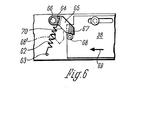
- a housing of a card reader has a front housing wall 1 and a rear housing wall 2, which are connected to one another by side walls 3 and 4 and intermediate walls 5 and 6.
- the upper wall 7 is only partially and broken away in Fig. 1, it is not shown in the other figures, it extends over the entire housing.
- a drive motor 8 is fixed, which drives a threaded spindle 9 via a gear, not shown, which is rotatably mounted in the intermediate walls 5 and 6.
- a guide rod 10 is also attached at a distance from the threaded spindle 9, on which a carriage 11 is guided, which has a magnetic head 12 at a distance from the guide rod 10 and on the side of the guide rod 10 facing away from the information head 12
- Rolls 13 and 14 carries.
- the roller 14 has on its periphery a bead 15, with which it engages in the thread base of the threaded spindle.
- the circumference of the roller 13 is cylindrical, it rolls on the space 16 between the thread base of the threaded spindle.
- the rollers 13 and 14 are pressed together by springs, not shown. If the threaded spindle 9 rotates, the carriage 11 is moved along the guide rod 10 by the roller 14.
- a pressure roller which presses it in the area of the card 17 inserted into the housing against the magnetic head 12 which slides over the magnetic track 18 in which the information is stored.
- an insertion slot 19 which is only slightly wider than the long side of the rectangular card 17 and whose height is only slightly larger than the thickness of such a card.
- the outer end of the insertion slot 19 is delimited by a housing part 20 which has a section 21 which projects beyond the rear card end when the card 17 is fully inserted into the slot 19 and which has a second section 22 via which the rear end 23 is completely card 17 inserted into the slot.
- the card 17 can be held at this rear end 23 when inserted and can be pulled out of the slot 19 again after the information exchange.
- the insertion movement of the card 17 in the slot 19 is limited by a stop rail 24 which is guided in the partition walls 5 and 6 in the insertion direction 25 of the card 17 against the action of a spring, not shown.
- the ends of the rail 24 passing through the intermediate walls 5 and 6 each carry a head 26 which carries an inclined surface 27 which, because the head 26 is screwed onto the ends of the rail 24 and therefore its position assumed when the head is screwed on, cannot be predicted, is designed as a cone.
- the insertion of the Card 17 delimiting rail 24 consists of a U-profile open towards the insertion side, into which the front end of the card inserted into the slot 19 enters, so that it cannot jump up or down even with strong impressions.
- Sensors 28 and 29 are displaceably mounted in the front housing wall and are pressed laterally into the insertion slot 19 by springs 30 and 31 at mutually opposite locations. These sensors 28 and 29 scan the size of the card between them.
- the housings of the switches 34 and 35 are fastened to the rear ends 32 and 33 of the sensors 28 and 29, which therefore also move in the axial direction of the sensors 28 and 29 when the sensors 28 and 29 are axially displaced when the card 17 is inserted into the insertion slot 19 move.
- the actuator 36 of the switches 34 and 35 has an inclined surface 37 which is formed by its bent tongue and which forms an angle of approximately 45 ° to the axial direction of the sensors 28, 29.
- the switch 34 is also moved outwards in the same direction, but the actuator 36 remains on the inclined surface 27 of the head part 26 due to the action of a spring acting on it the stop rail.
- the slight pivoting movement of the actuator 36 of the switch 34 does not yet actuate the switch 34. Only when the rail 24 is moved downwards in FIG. 3 by inserting the card the head 26 moves so far from the bent end of the actuator 36 of the switch 34 that the actuator 36 can perform its full pivoting movement under the action of the spring, not shown, and actuate the switch 34.
- the switches 34 and 35 at the two ends of the device are electrically connected in series, so that the circuit is only closed when both switches 34 and 35 are actuated.
- a slide 38 is slidably guided transversely to the direction of the insertion slot.
- a lever 39 is pivotally mounted on the slide, the other end of which is pivotably mounted on a lever 40 at a distance from its articulation 41 at 42.
- the lever 40 pivots in the first section of its displacement movement up to the position in which the magnetic head 12 reaches the card 17 under the action of the spring 43 to the extent that the carriage 11 extends removed from its rest position.
- the slider 38 moves to the left and then remains in a working position in which the lever end 42 also detaches from the carriage 11, so that the carriage 11 travels over the magnetic track 18 of the card 17 during the exchange of information, that is to say while the magnetic head 12 is moving , the lever 40 does not touch.
- the movement of locking members 45 and 46 is derived, which lock the card 17 in the position fully inserted into the insertion slot 19 during the exchange of information.
- the one ends of clamping parts 46 are mounted on the slide 38 so as to be pivotable about an axis 47.
- the parts 46 are also pivotally mounted about an axis 48 fixed to the housing, so that the ends 49 of the clamping parts 46 perform a pivoting movement about the axis 48 when the slide 38 moves.
- the axle bolts 47 engage in the clamping parts 46 with some play.
- the connecting line between the ends 49 and the axis 48 forms an angle of approximately 150 ° with the connecting line of the axes 47 and 48 and the distance of the ends 49 from the axis 48 is substantially smaller than the distance between the axes 47 and 48.
- the ends 49 have a curve, to which the edge of the clamping part 46 then extends obliquely upwards, so that even with a relatively small movement of the slide 38 to the right, the parts 46 completely release the slot 19.
- Fig. 2 the parts 46 are drawn in their engaged position, in which they press an inserted into the slot 19, not shown card against a table-like base 50.
- the slider 38 also has a slot guide 51, the central part 52 of which runs obliquely.
- the inner end 53 of a pivotably mounted rod 54 engages in this slot guide and is pivotably mounted about the axis 55 of a bearing disc 56 mounted in the housing wall 1 (not shown in FIG. 4).
- the end 57 facing away from the end 53 of the lever 54 engages in a recess in a locking pin 45.
- the locking pin 45 When pivoting the rod 54 in the direction of the double arrow 58, the locking pin 45 therefore moves in the direction of the double arrow 59.
- This locking pin 45 is displaceably mounted transversely to the plane of the insertion slot 19 in the housing section 21, in its upper position in FIG. 4 it engages behind the rear end of the card 17 in the insertion slot 19 and locks the card 17 in this position.
- the magnetic head 12 is then guided by driving the threaded spindle 9 over the track 18 applied to the card 17, in which the information is stored.
- the information is exchanged during this movement and the magnetic head reads the stored information or stores information in track 18.
- the carriage runs back and then takes the end 42 of the lever 40 into the rest position in the last movement section.
- the slide 38 is shifted to the right, the ends 49 of the links 46 are pivoted out of the insertion slot 19 and the pin 45 is moved downward in the housing part 21, so that it no longer projects into the insertion slot 19.
- the card 17 can be gripped at the end 23 protruding from the housing section 22 and pulled out again from the slot 19, the stop rail 24 as well as the switches 34 and 35 and the sensors 28 and 29 move back into their starting position.
- the drive of the spindle 9 has already been switched off by a circuit, not shown, after the carriage 11 has reached its rest position at the left end of the spindle.
- a spring 62 is provided instead of the spring 43, one end of which is in turn attached to a bolt 63 of the housing and the other end at 64 engages a tab 65 which is about a bolt fixed to the housing 66 is pivotally mounted.
- the free end of the tab 65 has a surface 67 which rests on a roller 68 which is rotatably mounted on the slide 38.
- the tension spring 62 endeavors to pivot the tab 65 clockwise.
- the head 11 When moving from the working position to the rest position, the head 11 engages the lever transmission 42, 40, 44, 39, which is designed so that it increases the force exerted by the carriage 11 on the lever end 42 after leaving the card.
- the slide 38 is moved back to its starting position against the force exerted by the surface 70 on the roller 68 and by overcoming the frictional resistance created by the clamping of the parts 46 on the card 17, that is to say the self-locking of the clamping of these parts is released.
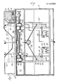
- 110 denotes a front part and 111 a housing part.
- the end part 110 is provided with an indentation which extends on the one hand in the horizontal direction, as denoted by 112, but on the other hand also in the vertical direction, as is shown in FIG. 8 is designated by 113.
- the indentation ends in a slot 123 into which a card 114 can be inserted along an insertion path 115, 116.
- the card 114 is drawn in continuously in a position in which it is fully inserted into the device. As can be seen in the partial section at the top right in FIG. 7, the card 114 meets a first one on its way along the insertion path 115, 116 when it is first inserted into the front part 110 Slider 117 which, when the card 114 is not inserted, projects beyond the insertion path 115 into the slot 123.
- the first slide 117 as shown in FIG. 7, is deflected to the right against the force of a spring 118, which is supported on a wall 119 of the front part 110.
- the first slide 117 moves along a guide 120 and a pin 122 of a switch not shown in FIG. 7, which extends into a recess 121 in the first slide 117, is deflected. With this mechanism it is therefore possible to recognize the insertion of the card 114 into the slot 123 along the insertion path 115, 116.
- a motor 125 is briefly connected to the supply voltage, for example via the series connection of two switches mentioned.
- the motor 125 rotates a shaft 126 which is mounted in bearing blocks 127, 128.
- the shaft 126 carries a first one Eccentric pair 130, 131.
- This eccentric pair 130, 131 actuates a first lock 132 in the manner shown in more detail below, which in the embodiment shown in the figure has the form of a sheet which slits the slot 123 when the card 114 is not inserted in the region of the Entry of the slot 123 blocked in the housing part 111.
- This first lock thus prevents possible manipulation of the device, since the slot 123 is closed when the card is not inserted. Only when, as described, a card 114 with the correct width is inserted into the slot 123, does the first lock 132 open the way for the card 114 into the housing part 111 by briefly actuating the motor 125 and rotating the eccentrics 130, 131.
- the card 114 can be inserted into the housing part 111 along the insertion path 115, 116 and encounters second sliders 136, 137 there, which are arranged displaceably in the housing part 111 in the manner described in detail below.
- the second slides 136, 137 actuate switches 138, 139, which can also be in series, for example, so that actuation of both switches 138, 139 by a card of the correct size leads to the closing of a circuit.
- This circuit actuates the motor 125 again briefly, so that now a further, second pair of eccentrics 140, 141, which is also arranged on the shaft 126, takes effect.
- the second pair of eccentrics 140, 141 actuates a second lock in the form of two hooks 142, 143 which reach behind the back of the card 114 and fix it against pulling out. In this way, the card 114 is held during the data exchange, so that a reading or writing unit 165 can carry out the data exchange from the device to the card 114 without being disturbed.
- the first lock 132 consists of a sheet metal part which is bevelled on the upper side.
- a first tab 145 is attached to the center of the top of the first lock 132.
- a spring wire 146 is arranged below the first tab 145 and engages in recesses 147, 148 which are formed on the bearing blocks 127, 128.
- a second tab 150 and a third tab 151 are integrally formed on the lock 132. These tabs 150, 151 are operatively connected to the first pair of eccentrics 130, 131.
- the eccentric 130 is shown in a position into which it was rotated by the motor 125 after actuation of the first slide 117 by the card 114. The eccentric 130 does not engage the tab 150 in this position, so that the first lock 132, held elastically by the spring wire 146, can sag downward in the housing part 111. In this position, the first lock 132, as can be seen from FIGS. 8 and 9, clears the way for the card 114.
- the first eccentric 130 is rotated clockwise and consequently, as can be seen from FIG. 8, engages the tab 150.
- the eccentric 130 then pushes the tab 150 upward, so that the first lock 132 blocks the opening of the slot 123 in the housing part 111.
- the card 114 After the card 114 enters the housing part 111, it initially encounters a hold-down device 170, which is held by a spring 171 which is supported against a cover 172 of the housing part 111. At the end facing the card entry, the hold-down device 170 is provided with a first bevel 173, so that the card 114, even if it is slightly bent at the edges, safely reaches below the hold-down device 170. After passing through the hold-down device 170 and the read / write unit 165, the card 114 encounters the second sliders 136, 137, which are provided with a second bevel 174 at their end facing the card 114.
- the card 114 runs on a table 175 which forms an intermediate floor of the housing part 171 until it abuts a stop 176 of the table 175.
- a floor 177 then extends from the stop 176 to the rear wall of the housing part 111, in which the second slides 136, 137 run when the card 114 is inserted.
- FIG. 12a shows the second slide 136 in a side view; the figures 12b and 12c show sections along the line DD 'and EE' of Fig. 12a.
- the second slide 136 has a profiled, plier-like shape, the upper and lower parts being held together by a common body 180.
- the upper part consists of a flange 181, which ends laterally in spring-shaped flanges 182, 183.
- the spring-like flanges 182, 183 terminate in a stop 184 on the left end face in FIG. 12a.
- the pliers-like shape of the second slide 136 is formed by an incision 185 running in the longitudinal direction. Below the incision 185 is the lower part of the second slide 136, which, immediately adjacent to the incision 185, ends in two spring-like flanges 186, 187, which form a stop 188 at their right end in FIG. 12a. In the lower area, the second slide 136 then runs out into a central web 193 which has an opening 194 for receiving a spring 195.
- the second slide 136 When the card 114 is not inserted, the second slide 136 is in the position not shown in FIG. 11.
- the incision 185 then encompasses the table 175, the spring-like flanges 182, 183 sliding on its upper side and the spring-like flanges 186, 187 on its lower side. If the card 114 is now inserted into the slot 123, after passing through the hold-down device 170 and the read / write unit 165 it comes into engagement with the stop 184 and pushes the second slide 136 in FIG. 11 to the right.
- the guide of the second slide 136 is thereby caused by the spring-like flanges 182, 183 which run in corresponding grooves in the bottom 177. During this displacement of the second slide 136, 137, the spring 195 is deflected.
- the switch 138 consists of a switch housing 190 to which a switching arm 191 is pivotably articulated.
- connections 192 emerge from the switch housing 190.
- An extension of the switching arm 191 protrudes into an opening 196 of the guide for the second slide 136, 137. If the second slide 136 is now moved further and further (downward in FIG. 7, to the right in FIG. 11), the stop 188 finally arrives of the spring-like flange 187 engages with the switch arm 191 and thus actuates the switch 138 before the card 114 abuts the stop 176.
Abstract
Description
Die Erfindung bezieht sich auf eine Vorrichtung zum Auslesen und/oder Einspeichern einer Information eines kartenförmigen Datenträgers. Diese, eine Information tragenden Karten dienen beispielsweise als Kreditkarten oder Karten zur Identifizierung einer Person beim Betreten eines Betriebes.The invention relates to a device for reading out and / or storing information from a card-shaped data carrier. These cards carrying information serve, for example, as credit cards or cards for identifying a person when entering a company.
Bekannte Vorrichtungen der eingangs genannten Art dienen dazu, um Kreditkarten, Scheckkarten, Eintrittsausweise oder dergleichen zu identifizieren. Kartenleser, bei denen der Informationsaustausch bei im Kartenleser feststehender Karte erfolgt, weisen bisher eine feststehende Auslesevorrichtung auf, die beispielsweise auf Löcher, auf kapazitive oder induktive, in der Karte angeordnete Elemente anspricht. Bei anderen bekannten Kartenlesern ist die Information in einer auf der Karte angebrachten Magnetspur enthalten und die Karte wird von einer Antriebsvorrichtung mit konstanter Geschwindigkeit an einem feststehenden Magnetkopf vorbeigezogen, der die in der Magnetspur gespeicherte Information ausliest und/oder einspeichert, zum Beispiel bei Bankautomaten.Known devices of the type mentioned at the outset are used to identify credit cards, check cards, entry badges or the like. Card readers in which the information is exchanged when the card is fixed in the card reader have hitherto had a fixed reading device which responds, for example, to holes, to capacitive or inductive elements arranged in the card. In other known card readers, the information is contained in a magnetic track attached to the card and the card is pulled by a drive device at a constant speed past a fixed magnetic head, which reads out and / or stores the information stored in the magnetic track, for example in automated teller machines.
Derartige Vorrichtungen können so ausgebildet sein, daß entweder nur eine auf der Karte enthaltene Information ausgelesen wird, es ist aber auch möglich, zusätzlich eine Information in die Karte einzuschreiben, beispielsweise einen Kontostand. Im letztgenannten Fall kann eine an die Vorrichtung angeschlossene Datenverarbeitungsanlage den gegenwärtigen Kontostand von der Karte ablesen und eine Veränderung des Kontostandes wieder in die Karte einschreiben. Ein derartiges Verfahren kann beispielsweise bei Fahrausweisen verwendet werden, bei denen bei Fahrtantritt und Fahrtende entsprechende Signale erzeugt werden und die ermittelte Fahrstrecke in Form von Gebühreneinheiten so lange von der Karte "abgebucht" wird, bis der beim Kauf der Karte entrichtete Gesamtfahrpreis verbraucht ist.Devices of this type can be designed such that either only information contained on the card is read out, but it is also possible to additionally write information into the card, for example an account balance. In the latter case, a data processing system connected to the device can read the current account balance from the card and write a change in the account balance back into the card. Such a method can be used, for example, for tickets in which corresponding signals are generated at the start and end of the journey and the determined route is "debited" from the card in the form of fee units until the total fare paid when the card was purchased is used up.
Bei all den bekannten Kartenlesern, insbesondere denen mit während des Informationsaustausches feststehenden Karten besteht das Bedürfnis, daß die Karte beim Einstecken in den Kartenleser in die richtige Ableseposition gelangt und daß sie in dieser Ableseposition während des Informationsaustausches zwischen Karte und Auslesevorrichtung unverrückbar stillsteht und auch bei Einwirkungen von außen nicht ihre Lage ändern kann.With all the known card readers, especially those with cards that are stationary during the information exchange, there is a need for the card to come into the correct reading position when it is inserted into the card reader, and for it to remain immovably in this reading position during the information exchange between the card and the reading device and also in the event of effects cannot change their position from the outside.
Dieses Problem hat man bisher dadurch gelöst, daß der Kartenleser von Hand in ihn eingesteckte Karten übernimmt und zum Informationsaustausch in eine von außen nicht mehr zugängliche Position überführt, also unter dem Informationskopf vorbeibewegt und nach dem Ein- und/oder Auslesen wieder in eine Position zurückbefördert, in der die Karte wieder von außen mit der Hand ergriffen wird und abgenommen werden kann. Fehlt ein derartiger Kartentransport, so darf die Karte nur so weit in den Kartenleser eingesteckt werden, daß ein Abschnitt der Karte noch von außen ergriffen wird und nach dem Informationsaustausch wieder aus dem Gerät von Hand herausgenommen werden kann.This problem has so far been solved in that the card reader takes cards inserted into it by hand and transfers them to a position that is no longer accessible from the outside for information exchange, that is to say passes under the information head and, after reading in and / or reading out, transports them back into a position , in which the card is again gripped by hand from the outside and can be removed. If such a card transport is missing, the card may only be inserted into the card reader to such an extent that a section of the card is still gripped from the outside and can be removed from the device by hand after the information exchange.
Der Erfindung liegt daher die Aufgabe zugrunde einen Kartenleser mit einer während des Informationsaustausches feststehenden Karte zu entwickeln, bei dem zur Erhöhung der Betriebssicherheit und der Sicherung gegen Mißbrauch der Informationsaustausch nur dann stattfindet, wenn die Karte in der richtigen Position ist, und bei dem der Informationsaustausch nicht gestört werden kann, obwohl ein Teil der Karte noch aus dem Gerät heraussteht und mit der Hand ergriffen werden kann.The invention is therefore based on the object of developing a card reader with a fixed card during the information exchange, in which to increase operational security and to protect against misuse, the information exchange only takes place when the card is in the correct position, and in which the information exchange cannot be disturbed, although part of the card still protrudes from the device and can be gripped by hand.
Diese Aufgabe wird gemäß der Erfindung zunächst dadurch gelöst, daß der Kartenleser an mindestens einem seitlichen Rand eines Schlitzes zum Einstecken der Karten mindestens ein Fühler vorgesehen ist, der nur dann ein Ingangsetzen des Informationsaustausches freigibt, wenn er sich in einer durch die Karte ausgelenkten Stellung befindet.This object is first achieved according to the invention in that the card reader is provided on at least one side edge of a slot for inserting the cards, at least one sensor which only enables the exchange of information to be started when it is in a position deflected by the card .
Werden in der üblichen Weise rechteckige Karten verwendet, so wird immer dann die Karte in der richtigen Lage in den Kartenleser eingesteckt, wenn der Schlitz des Kartenlesers nur um das notwendige Spiel breiter ist als die Länge der kleineren Rechteckseite. Durch das Maß des Einsteckschlitzes bedingt muß dann die Karte stets der Länge nach in den Kartenleser eingeführt werden. Dies hat jedoch den Nachteil, daß die Fläche, die zur Speicherung der Information auf der Karte zur Verfügung steht, im wesentlichen durch das Maß der Schmalseite des Rechtecks bestimmt ist. Entspricht jedoch die Breite des Einsteckschlitzes dem Maß der größeren Rechteckseite, so besteht die Möglichkeit, die Karte der Breite nach in diesen Schlitz einzustecken, so daß die für das Einspeichern der Information zur Verfügung stehende Fläche durch das Maß der längeren Rechteckseite bestimmt ist. Allerdings hat ein auf die längere Rechteckseite der Karte abgestimmter Einsteckschlitz den Nachteil, daß die Karte nicht nur, wie erwünscht, der Breite nach, sondern auch der Länge nach in den Einsteckschlitz eingeschoben werden kann, wodurch Möglichkeiten eines Mißbrauchs eröffnet werden.If rectangular cards are used in the usual way, the card is always inserted in the correct position in the card reader if the slot of the card reader is only wider by the necessary play than the length of the smaller side of the rectangle. Due to the size of the slot, the card must always be inserted lengthways into the card reader. However, this has the disadvantage that the area available for storing the information on the map is essentially determined by the size of the narrow side of the rectangle. If, however, the width of the insertion slot corresponds to the size of the larger side of the rectangle, there is the possibility of inserting the card into the width of this slot, so that the area available for storing the information is determined by the size of the longer side of the rectangle. However, a slot that is matched to the longer rectangular side of the card has the disadvantage that the card can not only be inserted into the slot, as desired, in width, but also in length, which opens up opportunities for misuse.
Die erfindungsgemäße Ausbildung hat demgegenüber den Vorteil, daß nur dann der Informationsaustausch in Gang gesetzt wird, wenn die Karte der Breite nach eingesteckt wird. Die erfindungsgemäße Ausbildung kann jedoch nicht nur dann mit Vorteil verwendet werden, wenn die Karten der Breite nach in den Kartenleser eingeschoben werden, sondern auch dann, wenn Karten bestimmungsgemäß der Länge nach in den Kartenleser eingeschoben werden. In diesem Falle ist durch die Erfindung gewährleistet, daß nur solche Karten einen Informationsaustausch herbeiführen können, bei denen die Länge oder die Breite der Karte so genau mit der Schlitzbreite übereinstimmt, daß die Fühler in diesem Schlitz soweit ausgelenkt werden, daß der Informationsaustausch in Gang gesetzt wird.In contrast, the design according to the invention has the advantage that the information exchange is only started when the width of the card is inserted. The design according to the invention can, however, be used not only when the cards are inserted into the card reader in width, but also when cards are inserted into the card reader according to their length. In this case it is ensured by the invention that only those cards can bring about an exchange of information in which the length or width of the card matches the slot width so precisely that the sensors in this slot are deflected to such an extent that the information exchange is started becomes.
Bei Ausführungsformen der Erfindung können an beiden seitlichen Rändern des Einsteckschlitzes einander gegenüber liegende Fühler vorgesehen sein, und die durch diese Fühler betätigten Schaltmittel können so hintereinander geschaltet sein, daß nur dann die Möglichkeit eines Informationsaustausches besteht, wenn beide Fühler in ihrer durch eine zugeordnete Karte ausgelenkten Stellung stehen. Es ist dann also nicht möglich, daß der Informationsaustausch durch eine schräg eingesteckte Karte eingeschaltet wird.In embodiments of the invention, opposite sensors can be provided on both lateral edges of the insertion slot, and the switching means actuated by these sensors can be connected in series so that there is only the possibility of information exchange if both sensors are deflected in their by an assigned card Position. It is then not possible for the information exchange to be switched on by an obliquely inserted card.
Die Erfindungsaufgabe wird außerdem dadurch gelöst, daß der Kartenleser mindestens eine Sperre zum Festhalten der Karte während des Informationsaustausches aufweist. Dadurch wird verhindert, daß die Karte während des Informationsaustausches bewegt werden kann, obwohl ein Teil der Karte sich noch außerhalb des Kartenlesers befindet.The object of the invention is also achieved in that the card reader has at least one lock for holding the card during the exchange of information. This prevents the card from being moved during the information exchange, even though part of the card is still outside the card reader.
Bei Ausführungsformen der Erfindung können an den seitlichen Rändern des Einsteckschlitzes angeordnete Fühler mit der zuletzt erwähnten Sperre zum Festhalten der Karte kombiniert sein, so daß durch das Zusammenwirken dieser beiden Merkmale dem bei gewissen Verwendungszwecken des Kartenlesers erhöhten Sicherheitsbedürfnissen entsprochen wird.In embodiments of the invention, sensors arranged on the lateral edges of the insertion slot can be combined with the last-mentioned lock for holding the card, so that the interaction of these two features meets the increased security requirements for certain uses of the card reader.
Die Erfindung kann sowohl bei Ausführungsformen mit Vorteil angewendet werden, bei denen die Ablesevorrichtung in dem Kartenleser gerätefest angeordnet ist als auch bei Kartenlesern, bei denen ein Informationskopf über die auf der Karte magnetisch oder auf andere Weise eingespeicherte Information durch einen geräteeigenen Antrieb hinwegbewegt wird.The invention can be used to advantage both in embodiments in which the reading device is arranged fixed to the device in the card reader and in card readers in which an information head is moved over the information magnetically or otherwise stored on the card by a device-specific drive.
Bei einer Ausführungsform der Erfindung ist mindestens ein das Einschieben der Karte begrenzender Anschlag beweglich angeordnet, der nur in einer durch die Karte ausgelenkten Stellung den Informationsaustausch frei gibt. Dies hat den Vorteil, daß nur eine vollständige in den Leser eingesteckte Karte den Informationsaustausch frei gibt und bei einem vorzeitigen Herausziehen der Karte aus dieser Endlage der Informationsaustausch sofort unterbrochen wird. Dies eröffnet die Möglichkeit, unvollständige Informationen sofort wieder zu löschen, was beispielsweise bei Kreditkarten mit automatischer Einspeicherung des in Anspruch genommenen Kredits in die Karte Fehlermöglichkeiten weitgehend unterbindet.In one embodiment of the invention, at least one stop limiting the insertion of the card is movably arranged, which only releases the information exchange in a position deflected by the card. This has the advantage that only a complete card inserted into the reader enables the exchange of information and, if the card is removed prematurely from this end position, the exchange of information is interrupted immediately. This opens up the possibility of immediately deleting incomplete information, which largely eliminates the possibility of errors, for example in the case of credit cards with automatic storage of the credit drawn on the card.
Die erfindungsgemäße Sperre kann bei Ausführungsformen der Erfindung auf verschiedene Art und Weise ausgebildet sein. Bei einer Ausführungsform der Erfindung ist die Sperre als ein in eine Aussparung der Karte eingreifender Anschlag ausgebildet. Bei anderen Ausführungsformen der Erfindung ist die Sperre als ein am rückwärtigen Rand der Karte angreifendes Verriegelungsglied ausgebildet, zum Beispiel als beweglicher, in Sperrstellung den hinteren Rand der Karte übergreifender Haken. Diese Ausführungsformen haben den Vorteil, daß die Karte keine Aussparung aufweisen muß und daher handelsübliche Rohlinge verwendet werden können. Andererseits hat eine Aussparung in der Karte, in die bei eingesteckter Karte ein Verriegelungsglied eingreift, den Vorteil, daß diese Aussparung als zusätzliches Identifizierungsmerkmal dient; Karten, die die Aussparung nicht aufweisen, werden von dem Kartenleser nicht angenommen.The lock according to the invention can be designed in various ways in embodiments of the invention. In one embodiment of the invention, the lock is designed as a stop engaging in a cutout in the card. In other embodiments of the invention, the lock is designed as a locking member which engages on the rear edge of the card, for example as a movable hook which overlaps the rear edge of the card in the locked position. These embodiments have the advantage that the card does not have to have a recess and therefore commercially available blanks can be used. On the other hand, a recess in the card, in which a locking member engages when the card is inserted, has the advantage that this recess serves as an additional identification feature; Cards that do not have the recess are not accepted by the card reader.
Bei einer Ausführungsform der Erfindung weist ein das äußere Ende des Einsteckschlitzes begrenzender Gehäuseteil einen Abschnitt, der bei vollständig in den Schlitz eingesteckter Karte über das hintere Kartenende hinausragt, und einen zweiten Abschnitt auf, über den das hintere Ende der vollständig eingesteckten Karte hinausragt. In dem ersten Abschnitt kann beispielsweise ein Verriegelungsglied, z.B. ein axial verschiebbarer Stift, gelagert sein, der beim Informationsaustausch hinter dem rückwärtigen Rand der Karte in den Schlitz eingreift und so die Karte verriegelt. Der andere Gehäuseabschnitt dagegen tritt gegenüber dem hinteren Rand der Karte zurück, so daß im Bereich dieses Abschnittes die vollständig eingesteckte Karte immer noch mit der Hand bequem erfaßt und nach dem Informationsaustausch und der Entriegelung der Karte wieder aus dem Kartenleser herausgenommen werden kann.In one embodiment of the invention, a housing part delimiting the outer end of the insertion slot has a section which projects beyond the rear end of the card when the card is fully inserted into the slot, and a second section which extends beyond the rear end of the fully inserted card. In the first section, for example, a locking member, for example an axially displaceable pin, can be mounted, which engages in the slot behind the rear edge of the card during the exchange of information and thus locks the card. The other housing section, on the other hand, steps back towards the rear edge of the card, so that the completely inserted card is still in the area of this section easily grasped by hand and after exchanging information and unlocking the card can be removed again from the card reader.
Bei Ausführungsformen der Erfindung kann die Sperre auch oder zusätzlich die Karte gegen eine Unterlage anpreßende Hebel aufweisen, die vorzugsweise nach Art von Klemmgesperren beweglich geführt sein können. Dabei können die Antriebe der beiden Sperrvorrichtungen miteinander gekoppelt sein. Auch dadurch ergibt sich eine sichere Verriegelung der Karte während des Informationsaustausches. Außerdem hat diese Ausführungsform der Erfindung den Vorteil, daß sie Karten, die durch das Tragen in der Tasche etwas gewölbt sind, durch das Anpressen gegen eine ebene Unterlage gerade richtet, so daß ein über die Karte geführter Informationskopf eine ebene Informationsspur vorfindet.In embodiments of the invention, the lock can also or additionally have levers pressing the card against a base, which can preferably be movably guided in the manner of clamping ratchets. The drives of the two locking devices can be coupled to one another. This also results in a secure locking of the card during the exchange of information. In addition, this embodiment of the invention has the advantage that it straightens cards which are somewhat curved due to being carried in the pocket by being pressed against a flat base, so that an information head guided over the card finds a flat information track.
Bei weiteren Ausführungsformen der Erfindung ist eine Einrichtung zum Ingangsetzen des Informationsaustausches durch ein beim Einschieben der Karte bewegtes Teil vorbereitbar und durch einen Endanschlag auslösbar. Auch diese Ausführungsform dient der zusätzlichen Sicherung gegen Mißbrauch und Beschädigung. Die den Informationsaustausch vornehmenden Teile sind meist empfindlich, sie sollen, wenn diese Teile nicht feststehen sondern im Gehäuse über die Karte hinweg bewegbar angeordnet sind, nicht in den Bereich des Schlitzes bewegt werden können, wenn ein anderer Gegenstand als die Karte gegen den Endanschlag gedrückt wird. Daher wird bei einer Ausführungsform der Erfindung das beim Einschieben der Karte bewegte Teil durch ein oder zwei der bereits im vorhergehenden beschriebene Fühler gebildet, die seitlich in den Einsteckschlitz hineinragen und das Seitenmaß der Karte abtasten.In further embodiments of the invention, a device for starting the information exchange can be prepared by a part moved when the card is inserted and can be triggered by an end stop. This embodiment also serves as an additional safeguard against misuse and damage. The parts carrying out the information exchange are usually sensitive; if these parts are not fixed but are arranged in the housing so that they can be moved over the card, they should not be able to be moved into the area of the slot when an object other than the card is pressed against the end stop . Therefore, in one embodiment of the invention, the part moved when inserting the card is replaced by one or two of the parts already in the previously described sensors formed, which protrude laterally into the insertion slot and scan the lateral dimension of the card.
Das Vorbereiten durch ein beim Einschieben der Karte bewegtes Teil und das Auslösen durch einen Endanschlag kann in üblicher Weise über Mikroschalter erfolgen, die beispielsweise hintereinander geschaltet sind und beispielsweise in den Stromkreis eines Antriebsmotors eingeschaltet sind, der mit Hilfe einer Gewindespindel einen Antriebskopf über die auf der Karte enthaltene Information hinweg bewegt wird. Um jedoch einen besonderen Grad der Betriebssicherheit zu gewinnen, wird dieses Vorbereiten und Auslösen des Informationsaustausches bei anderen Ausführungsformen der Erfindung mechanisch verwirklicht.The preparation by a moving part when inserting the card and the triggering by an end stop can be done in the usual way via microswitches, which are connected in series, for example, and are switched on, for example, in the circuit of a drive motor, which uses a threaded spindle to drive a drive head over the Card contained information is moved away. However, in order to gain a special degree of operational security, this preparation and triggering of the information exchange is realized mechanically in other embodiments of the invention.
Bei Ausführungsformen der Erfindung ist ein Gehäuse eines Schalters für das Ingangsetzen des Informationsaustausches in zwei Stellungen bewegbar geführt und seine Bewegung in zumindest eine der beiden Stellungen ist von der Bewegung eines durch das Einschieben der Karte bewegten Teiles abgeleitet, also beispielsweise von der Bewegung eines oder mehrerer die Breite der Karte abtastenden Fühler, und die Bewegung eines auf das Betätigungsglied des Schalters einwirkenden Teiles ist von der Bewegung des das Einschieben der Karte begrenzenden Anschlages geleitet. Dabei können die Schalter mit den Fühlern mechanisch verbunden sein und daher in Achsrichtung der Fühler beweglich sein.In embodiments of the invention, a housing of a switch for starting the information exchange is movably guided in two positions and its movement in at least one of the two positions is derived from the movement of a part moved by the insertion of the card, for example from the movement of one or more the width of the card scanning sensor, and the movement of a part acting on the actuator of the switch is guided by the movement of the stop limiting the insertion of the card. The switches can be mechanically connected to the sensors and can therefore be movable in the axial direction of the sensors.
Damit die Bewegung der Fühler und des Endanschlages mechanisch hintereinander geschaltet sind, weisen, wenn die Bewegung des Endanschlages rechtwinklig zu der Bewegung der Fühler und des Schalters verläuft, das Betätigungsglied und das auf dieses einwirkende, mit dem Endanschlag verbundene Teil schräg zu ihrer Bewegungsrichtung verlaufende, aneinander zur Anlage kommende Schrägflächen auf. Dadurch wird erreicht, daß sich rechtwinklig zueinander verlaufende Bewegungen in dem Abstand der Schrägflächen addieren und nur dann, wenn beide Teile eine Bewegung durchgeführt haben, das Betätigungsglied des Schalters entweder vollständig entlastet ist oder aber vollständig gedrückt ist.So that the movement of the sensors and the end stop are connected mechanically one after the other, if the movement of the end stop is perpendicular to the movement of the sensors and the switch, the actuating element and the part acting on it and connected to the end stop run obliquely to their direction of movement. sloping surfaces coming into contact with one another. It is thereby achieved that movements perpendicular to each other add up in the distance between the inclined surfaces and only when both parts have carried out a movement, the actuator of the switch is either completely relieved or is fully pressed.
Die Bewegung der die Sperre bildenden Teile in die Sperrstellung kann vom Antrieb eines Informationskopfes abgeleitet sein. Bei anderen Ausführungsformen der Erfindung erfolgt die Bewegung der die Sperre bildenden Teile in die Sperrstellung jedoch durch Federwirkung. Dies hat den Vorteil, daß hierdurch auch die Karten nur anpreßende Sperrglieder sicher betätigt werden können, denn diese können im Gegensatz zu den Aussparungen in der Karte durchsetzenden Riegeln wegen den Toleranzen der Kartendicke oder bei etwas gebogenen Karten nicht bei jeder Karte ganz genau die gleiche Sperrstellung einnehmen.The movement of the parts forming the lock into the locked position can be derived from the drive of an information head. In other embodiments of the invention, however, the movement of the parts forming the lock into the locked position takes place by spring action. This has the advantage that the cards can only be securely actuated by pressing locking elements because, in contrast to the bars in the card which have cut-outs, they cannot have the exact same locking position for each card due to the tolerances of the card thickness or with slightly bent cards take in.
Diese Ausführungsform der Erfindung kann dahingehend weiter ausgebildet sein, daß die Bewegung eines die Sperrglieder entgegen der Federwirkung in der entsperrten Lage haltenden Sicherungsgliedes in seine Entsicherungsstellung von der Bewegung eines Informationskopfes innerhalb eines ersten Bewegungsabschnittes abgeleitet ist, wobei der Informationskopf erst nach Durchlaufen des ersten Bewegungsabschnittes und damit erst nach Entsichern der die Karte verriegelnden Sperrglieder die auf der Karte enthaltene Spur erreicht, in der die Information eingespeichert ist.This embodiment of the invention can be further developed in such a way that the movement of a locking member holding the locking members against the spring action in the unlocked position into its unlocking position is derived from the movement of an information head within a first movement section, the information head only after passing through the first movement section and thus only after unlocking the locking elements locking the card, does the track contained on the card reach, in which the information is stored.
Diese Ausführungsform der Erfindung kann dahingehend weiter ausgebildet sein, daß in dem Gehäuse ein Schieber verschieb- bar geführt ist, von dessen Bewegung die Bewegung der Sperrglieder abgeleitet ist, daß an dem Schieber eine ihn in eine der Sperrstellung der Sperrglieder entsprechende Arbeitsstellung ziehende Feder angreift und daß eine Hebelübersetzung vorgesehen ist, über die der Schieber von dem sich zurückbewegenden Informationskopf entgegen der Wirkung der Feder in seine Ruhelage bewegbar ist.This embodiment of the invention may be designed to the effect further, that in the housing displaceable a spool - is guided bar, the movement of the locking members is derived from the movement of that one engages the slide him corresponding working position pulling spring in one of the locked position of the locking members and that a lever transmission is provided, by means of which the slide can be moved into its rest position by the information head moving back against the action of the spring.
Bei Ausführungsformen der Erfindung sind die als Klemmgesperre wirkenden Sperrhebel als zweiarmige Winkelhebel ausgebildet, deren eines Ende in dem Schieber schwenkbar gelagert ist und deren anderes Ende zum Eingriff in den Einsteckschlitz bestimmt ist, dessen Winkelscheitel jedoch in dem Gehäuse schwenkbar gelagert ist. Dabei ist der Abstand der Lagerachse im Gehäuse von der Lagerachse im Schieber größer als der Abstand der Lagerachse im Gehäuse von dem in den Einsteckschlitz eingreifenden Hebelende. Der Winkel des einen Hebelarmes, der die beiden Lagerachsen miteinander verbindet, zu dem anderen Hebelarm des Winkelhebels, der die am Winkelscheitel befindliche Lagerachse mit dem freien, in den Einsteckschlitz eingreifenden Hebelendes verbindet, ist so gewählt, beispielsweise zwischen 150 und 170°, daß mit verhältnismäßig geringen, die Schwenkbewegung der Hebel bewirkenden Kräften ein sehr hoher Anpreßdruck der in den Einsteckschlitz eingreifenden und die Karte auf die Unterlage anpreßenden Hebelenden erzeugt wird.In embodiments of the invention, the locking levers acting as a clamping lock are designed as two-armed angle levers, one end of which is pivotably mounted in the slide and the other end of which is intended for engagement in the insertion slot, but the angle apex of which is pivotally mounted in the housing. The distance of the bearing axis in the housing from the bearing axis in the slide is greater than the distance of the bearing axis in the housing from the lever end engaging in the insertion slot. The angle of one lever arm, which connects the two bearing axles to one another, to the other lever arm of the angle lever, which connects the bearing axis located at the angle vertex to the free lever end engaging in the insertion slot, is selected, for example between 150 and 170 °, with comparatively low, the pivoting movement of the lever-causing forces, a very high contact pressure which engages in the insertion slot and presses the card onto the base of the lever ends is generated.
Bei Ausführungsformen der Erfindung ist die Bewegung eines in den Einsteckschlitz des Gerätes eingreifenden Verriegelungsstiftes ebenfalls von der Bewegung des Schiebers abgeleitet. Beispielsweise kann der Schieber eine Schrägführung aufweisen, in die das innere Ende eines zweiarmigen Hebels eingreift, der in dem Gehäuse schwenkbar gelagert ist und dessen äußeres Ende in eine Aussparung eines Verriegelungsstiftes eingreift, der in dem Gehäuse quer zum Einsteckschlitz beweglich hinter dem rückwärtigen Ende der vollständig eingeführten Karte in den Einsteckschlitz einfiihrbar ist. Dies ergibt eine besonders einfache Ausbildung des Antriebs des Sicherungsstiftes.In embodiments of the invention, the movement of a locking pin which engages in the insertion slot of the device is also derived from the movement of the slide. For example, the slider can have an oblique guide, into which the inner end of a two-armed lever engages, which is pivotally mounted in the housing and whose outer end engages in a recess of a locking pin which is movable in the housing transversely to the insertion slot behind the rear end of the complete inserted card can be inserted into the slot. This results in a particularly simple design of the drive of the locking pin.
Bei Ausführungsformen der Erfindung besteht der Endanschlag aus einer Schiene mit einem nach der Einschubseite hin offenen U-Profil, wobei die Schiene in Einschubrichtung beweglich gelagert ist. Außerdem kann bei Ausführungsformen der Erfindung zwischen der den Endanschlag bildende Schiene und dem inneren Ende des Einsteckschlitzes ein Zwischenraum bestehen. Diese Ausbildung eignet sich besonders für Ausführungsformen der Erfindung, bei denen die Karte durch einen beweglichen Informationskopf abgetastet wird. Dieser Zwischenraum ermöglicht es dann, daß von einem beweglichen Wagen, der den Informationskopf über die Informationsspur auf der Karte führt, eine Gegendruckrolle an die Unterseite der Karte angedrückt wird.In embodiments of the invention, the end stop consists of a rail with a U-profile which is open towards the insertion side, the rail being mounted so that it can move in the insertion direction. In addition, in embodiments of the invention, there may be a gap between the rail forming the end stop and the inner end of the insertion slot. This design is particularly suitable for embodiments of the invention in which the card is scanned by a movable information head. This intermediate space then enables a moving carriage, which guides the information head over the information track on the card, to press a counterpressure roller onto the underside of the card.
Eine weitere Möglichkeit zur Manipulation der Vorrichtung liegt darin, daß flache Gegenstände durch den Einführungsschlitz für die Karte in die Vorrichtung eingeführt werden können, dabei ist es weiterhin möglich, das Innere der Vorrichtung, insbesondere die sehr empfindliche Schreib-/Leseeinheit zu beschädigen.Another possibility for manipulating the device is that flat objects can be inserted into the device through the slot for inserting the card, it is also possible to damage the inside of the device, in particular the very sensitive read / write unit.
Der Erfindung liegt ferner die Aufgabe zugrunde, einen Kartenleser mit einer während des Informationsaustausches feststehenden Karte zu entwickeln, bei dem zur Erhöhung der Betriebssicherheit und der Sicherung gegen Mißbrauch das Einstecken der Karte erst dann ermöglicht wird und der Informationsaustausch nur dann stattfindet, wenn die Karte in der richtigen Position ist, und bei dem der Informationsaustausch nicht gestört werden kann, obwohl ein Teil der Karte noch aus dem Gerät heraussteht und mit der Hand ergriffen werden kann.The invention is also based on the object to develop a card reader with a fixed during the exchange of information, in which to increase operational security and protection against misuse, the insertion of the card is only possible and the information is only exchanged when the card is in in the correct position, and in which the information exchange cannot be disrupted, even though part of the card still protrudes from the device and can be gripped by hand.
Diese weitere Aufgabe wird gemäß der Erfindung dadurch gelöst, daß der Fühler bei teilweise eingesteckter Karte ausgelenkt wird und eine das vollständige Einstecken der Karte versperrende bzw. freigebende erste Sperre betätigt.This further object is achieved according to the invention in that the sensor is deflected when the card is partially inserted and actuates a first lock that blocks or releases the complete insertion of the card.
Diese erfindungsgemäße Vorrichtung hat damit den erheblichen Vorteil, daß ein Informationsaustausch schon alleine dadurch unterbunden wird, daß ein anderer Gegenstand als eine Karte mit vorgegebenen Abmessungen überhaupt nicht in die Vorrichtung eingesteckt werden kann. Ein Mißbrauch der Vorrichtung oder eine Beschädigung ist damit weitgehend ausgeschlossen. Die letztgenannte Aufgabe wird gemäß der Erfindung weiterhin dadurch gelöst, daß die zweite Sperre bei vollständig eingesteckter Karte den Einsteckweg hinter der Karte an mindestens zwei Punkten versperrt.This device according to the invention thus has the considerable advantage that an exchange of information is prevented simply because an object other than a card with predetermined dimensions cannot be inserted into the device at all. Misuse of the device or damage is thus largely excluded. The latter object is further achieved according to the invention in that the second lock blocks the insertion path behind the card at least two points when the card is fully inserted.
Diese nebengeordnete Lösung der Erfindungsaufgabe hat den wesentlichen Vorteil, daß ein Herausziehen der Karte während des Informationsaustausches dadurch unmöglich wird, daß der Weg der Karte vollkommen versperrt wird. Gegenüber Einrichtungen, bei denen die Karte im eingesteckten Zustand mit einer Klemmvorrichtung von oben oder unten gehalten wird, hat die erfindungsgemäße Anordnung den Vorteil, daß ein Herausziehen der Karte selbst "mit Gewalt" nicht möglich ist. Dies betrifft auch Anordnungen, bei denen die Karte an ihrer Rückseite lediglich von einem einzelnen Sperrstift am seitlichen Kartenrand verriegelt wird, so daß die Karte bei kräftigem Angreifen am nichtverriegelten Kartenrand unter Umständen verkantet werden kann. Damit ist ein vollkommen sicherer und gegen Manipulationen und Störungen praktisch vollkommen gesicherter Betrieb während des Datenaustausches möglich.This subordinate solution to the object of the invention has the essential advantage that it is impossible to pull out the card during the exchange of information because the path of the card is completely blocked. Compared to devices in which the card is held in the inserted state with a clamping device from above or below, the arrangement according to the invention has the advantage that the card itself cannot be pulled out "by force". This also applies to arrangements in which the back of the card is locked only by a single locking pin on the side edge of the card, so that the card can be tilted under certain circumstances if the card edge is firmly engaged. This enables a completely secure operation that is practically completely secured against manipulation and malfunctions during data exchange.
Eine besonders perfekte Sicherung der Vorrichtung und des Arbeitsablaufes beim Datenaustausch ergibt sich dann, wenn in bevorzugter Ausgestaltung der Erfindung die beiden nebengeordneten Lösungen gemeinsam oder in Kombination mit den eingangs genannten Merkmalen eingesetzt werden.A particularly perfect backup of the device and the workflow during data exchange is obtained if, in a preferred embodiment of the invention, the two secondary solutions are used together or in combination with the features mentioned at the beginning.
Weiterhin ist eine Ausführungsform bevorzugt, bei der die Sperren durch ein gemeinsames Betätigungsorgan betätigt werden. Hiermit ergibt sich eine Minimierung der erforderlichen Bauelemente, ein besonders kompakter Aufbau und eine hohe Betriebssicherheit.Furthermore, an embodiment is preferred in which the locks are actuated by a common actuating member. This results in a minimization of the required components, a particularly compact structure and high operational reliability.
Besonders vorteilhaft ist dabei, das Betätigungsorgan als motorisch angetriebene Welle mit Exzentern auszubilden. Bei einem derartigen elektromechanischen Betätigungsorgan ist einmal eine flexible Arbeitsweise durch entsprechende Ansteuerung des Motors möglich, zum anderen ist die Betätigung der Sperren durch Exzenter besonders betriebssicher und kann auch ausreichende mechanische Kräfte ausüben.It is particularly advantageous to design the actuator as a motor-driven shaft with eccentrics. With such an electromechanical actuator, flexible operation is possible by controlling the motor accordingly, and secondly, the actuation of the locks by means of eccentrics is particularly reliable and can also exert sufficient mechanical forces.
Erfindungsgemäß kann zum Betätigen der ersten Sperre, die den Schlitz in das Innere der Vorrichtung überhaupt erst freigibt, diese durch erste Exzenter betätigt werden, die dann in Betrieb gesetzt werden, wenn die Karte die seitlich angeordneten Fühler betätigt. Sieht man dabei an jeder Seite des Schlitzes je einen Fühler in einem Abstand vor, bei dem beide Fühler nur dann betätigt werden, wenn eine Karte einer vorgegebenen Breite in den Schlitz eingesteckt wird, ist ein sicheres Erkennen einer vorgegebenen Kartenbreite möglich. Erfindungsgemäß betätigen die Fühler dabei Schalter, die logisch so verschaltet sind, vorzugsweise in Reihenschaltung, daß der Motor nur bei gleichzeitigem Ansprechen beider Schalter betätigt wird. Mit einer sehr einfachen Kodierung ist es daher möglich, vorgegebene Kartenformate sicher zu erkennen.According to the invention, in order to actuate the first lock, which in the first place releases the slot into the interior of the device, it can be actuated by first eccentrics, which are put into operation when the card actuates the sensors arranged on the side. If a sensor is provided on each side of the slot at a distance at which both sensors are only actuated when a card of a predetermined width is inserted into the slot, it is possible to reliably recognize a predetermined card width. According to the invention, the sensors actuate switches which are logically connected, preferably in series connection, in such a way that the motor is actuated only when both switches are activated at the same time. With very simple coding, it is therefore possible to reliably recognize predetermined card formats.
Wird die erste Sperre als ein den Schlitz in Ruhestellung verschließendes Blechteil ausgebildet, ist ein besonders einfacher und betriebssicherer Aufbau möglich. Bei kompaktem Aufbau des Geräteinneren kann das Blechteil so dicht geführt werden, daß ein gewaltsames Einführen eines Gegenstandes gegen das den Schlitz verschließende Blechteil praktisch unmöglich ist.If the first lock is designed as a sheet metal part closing the slot in the rest position, a particularly simple and reliable construction is possible. With a compact construction of the interior of the device, the sheet metal part can be guided so tightly that a violent insertion of an object against the sheet metal part closing the slot is practically impossible.
Um das Blechteil von den Exzentern betätigen zu können, wird es bevorzugt mit Laschen versehen, die von den Exzentern betätigt werden. Auf diese Weise kann eine Steuerung der Motordrehung in einfacher Weise in eine zur Einsteckbahn der Karte senkrechte Bewegungsrichtung des Blechteils umgesetzt werden.In order to be able to actuate the sheet metal part from the eccentrics, it is preferably provided with tabs which are actuated by the eccentrics. In this way, control of the motor rotation can be implemented in a simple manner in a direction of movement of the sheet metal part perpendicular to the insertion path of the card.
Wird das Blechteil erfindungsgemäß federnd aufgehängt, insbesondere indem ein Federdraht in einer an das Blechteil angeformten Lasche befestigt wird und an seinen Enden, vorzugsweise durch an Lagerböcken der Welle angeformte Aussparungen gehalten wird, kann eine Steuerung vorgesehen werden, bei der der Exzenter die Laschen des Blechteils in der Ruhestellung betätigt und das Blechteil vor den Schlitz schiebt, während bei eingeschobener Karte der Exzenter von der Lasche abhebt und das Blechteil dann vom Federdraht federnd aufgehängt gehalten wird. Diese Betriebsweise garantiert, daß bei verschlossenem Schlitz durch den Eingriff des Exzenters an der Lasche ein besonders stabiler Verschluß erzielt wird, während bei eingeschobener Karte das als Sperre dienende Blechteil lediglich lose federnd aufgehängt sein kann.If the sheet metal part is resiliently suspended according to the invention, in particular in that a spring wire is fastened in a tab formed on the sheet metal part and is held at its ends, preferably by recesses formed on bearing blocks of the shaft, a control can be provided in which the eccentric detaches the tabs of the sheet metal part actuated in the rest position and pushing the sheet metal part in front of the slot, while the eccentric lifts off the tab when the card is inserted and the sheet metal part is then held in a spring-loaded manner by the spring wire. This mode of operation guarantees that a particularly stable closure is achieved when the slot is closed by the engagement of the eccentric on the tab, while the sheet-metal part serving as a lock can only be suspended in a loosely resilient manner when the card is inserted.
Die zweite Sperre, die die Karte im vollständig eingesteckten Zustand festhält, wird bevorzugt von zweiten Exzentern betätigt, die ebenfalls von dem Motor angetrieben werden. Die zweite Sperre wird nur dann betätigt, wenn die Karte in vollständig eingestecktem Zustand Schalter betätigt. Auch diese elektromechanische Verriegelung kann - wie weiter oben schon ausgeführt - besonders einfach und wirkungsvoll aufgebaut werden.The second lock, which holds the card in the fully inserted state, is preferably actuated by second eccentrics, which are also driven by the motor. The second lock is only activated when the card operates the switch when it is fully inserted. This electromechanical locking system can also - as already explained above - be set up particularly simply and effectively.
Eine besonders gute Wirkung wird dabei dadurch erzielt, daß die Karte im eingesteckten Zustand mit ihren Randbereichen der in die Vorrichtung hineinweisenden Vorderkante zwei Schalter betätigt, die logisch so geschaltet sind, vorzugsweise in Reihenschaltung, daß der Motor nur bei gleichzeitigem Ansprechen beider Schalter betätigt wird. Wie bereits oben zur Betätigung der ersten Sperre ausgeführt, können auf diese Weise nur Karten mit vorgegebenen Dimensionen die Vorrichtung betätigen. Während jedoch die seitlichen Fühler der ersten Sperre auf ein korrektes Breitenmaß der Karte ansprechen, sprechen die in Einsteckrichtung der Karte wirkenden Schalter für die zweite Sperre auf eine gleichmäßige Höhe der Karte an, so daß bei der eingangs erwähnten möglichen Kombination der beiden nebengeordneten erfindungsgemäßen Lösungen eine Überwachung beider Kartendimensionen möglich ist.A particularly good effect is achieved in that the card actuates two switches with their edge areas of the front edge pointing into the device in the inserted state, which are logically connected, preferably in series connection, that the motor is actuated only when both switches respond simultaneously. As already stated above for the actuation of the first lock, only cards with predetermined dimensions can actuate the device in this way. However, while the lateral sensors of the first lock respond to a correct width of the card, the switches acting in the insertion direction of the card for the second lock respond to a uniform height of the card, so that in the possible combination of the two subordinate solutions according to the invention mentioned above, one Monitoring of both map dimensions is possible.
Durch Vorsehen der genannten Maßnahmen kann erfindungsgemäß eine Zeitsteuerung vorgesehen werden, die nach Wirksamwerden der zweiten Sperre eine Schreib-/Leseeinheit für den Datenaustausch von oder zu der Karte einschaltet und nach Beendigung des Datenaustausches die zweite Sperre wieder freigibt. Diese Zeitsteuerung stellt demnach sicher, daß die Karte während des Datenaustausches unverrückbar feststeht und unmittelbar nach Beendigung des Datenaustausches wieder von Hand entommen werden kann.By providing the above-mentioned measures, a time control can be provided according to the invention which, after the second lock takes effect, switches on a read / write unit for data exchange from or to the card and releases the second lock again after the data exchange has ended. This time control therefore ensures that the card is immovably fixed during the data exchange and can be removed by hand immediately after the end of the data exchange.
In bevorzugter Ausgestaltung der Erfindung wird die zweite Sperre von Haken gebildet, die in der Arbeitsstellung den bei eingesteckter Karte von der Vorrichtung wegweisenden Rand der Karte umfassen. Mit diesen Haken kann demnach sicher verhindert werden, daß die Karte während des Datenaustausches von Hand aus der Vorrichtung entfernt wird.In a preferred embodiment of the invention, the second lock is formed by hooks which, in the working position, comprise the edge of the card which points away from the device when the card is inserted. These hooks can therefore be used to reliably prevent the card from being manually removed from the device during data exchange.
Erfindungsgemäß umfaßt die Vorrichtung ein Stirnteil, das eine sich in horizontaler Richtung erstreckende Einbuchtung aufweist, derart, daß bei eingesteckter Karte deren mittlerer Bereich der Hinterkante noch mit der Hand ergriffen werden kann, während die seitlichen Ränder der Hinterkante sich bereits im Stirnteil befinden. Die Haken sind dabei im Stirnteil angeordnet. Diese Anordnung hat den besonderen Vorteil, daß ein Ergreifen der Karte von Hand nur in einem begrenzten Kartenbereich möglich ist, wenn diese vollständig in die Vorrichtung eingesteckt ist. Die mechanisch von Hand auf die Karte ausübbaren Kräfte sind damit beschränkt, wenn man sich vor Augen hält, daß die Karten üblicherweise aus Kunststoff mit glatter Oberfläche bestehen und bei der vorgesehenen Einbuchtung die Karte praktisch nur mit zwei Fingern ergriffen werden kann. Abgesehen von der Sicherung durch die genannten Haken kann damit auch nur eine verhältnismäßig geringe Kraft auf die Karte ausgeübt werden. Da die seitlichen Ränder der Hinterkante der Karte bei der geschilderten Anordnung bereits im Inneren des Stirnteils angeordnet sind, können in diesem Bereich die Haken der zweiten Sperre wirksam werden, ohne von außen sichtbar oder zugänglich zu sein. Damit sind auch die die zweite Sperre bildenden Haken vor Fremdeingriffen und damit Beschädigungen weitgehend geschützt, da sie nur in ihrer Arbeitsstellung in den die Einsteckbahn für die Karte bildenden Schlitz eingreifen und damit von außen praktisch nicht zugänglich sind.According to the invention, the device comprises a front part which has an indentation extending in the horizontal direction, such that when the card is inserted, the central region of the rear edge thereof can still be grasped by hand, while the lateral edges of the rear edge are already in the front part. The hooks are arranged in the front part. This arrangement has the particular advantage that the card can only be gripped by hand in a limited card area when it is fully inserted into the device. The forces that can be exerted mechanically on the card by hand are thus limited if one keeps in mind that the cards usually consist of plastic with a smooth surface and that the card can practically only be gripped with two fingers when the indentation is provided. Apart from the securing by the mentioned hooks, only a relatively small force can be exerted on the card. Since the side edges of the back edge of the card at the schil arrangement are already arranged inside the front part, the hooks of the second lock can take effect in this area without being visible or accessible from the outside. Thus, the hooks forming the second lock are largely protected from external interference and therefore damage, since they only engage in the working position in the slot forming the insertion path for the card and are therefore practically inaccessible from the outside.
Besonders bevorzugt ist eine Ausführungsform, bei der die Haken einen Arm eines um eine Achse schwenkbaren Hebels bilden, dessen anderer Arm in eine Gabel ausläuft, die zweite, auf der Welle angeordnete Exzenter umschließt. Die Verriegelung der Karte durch die zweite Sperre wird demnach durch Schwenkhebel gebildet, deren einer Arm die genannten Haken bildet. Die Auslenkung des Schwenkhebels kann in der genannten Form sehr einfach durch Verdrehen der Welle mit den darauf befindlichen Exzentern erfolgen. Auch diese Anordnung ist mechanisch besonders einfach und erlaubt es, ausreichende mechanische Kräfte innerhalb der zweiten Sperre wirksam werden zu lassen. Auch eine exakte Steuerung der Eingriffshöhe der Haken, die innerhalb des Schlitzes genau einzustellen ist, ist durch die genannte Anordnung möglich, da eine eindeutige Zuordnung des Verdrehwinkels der Exzenter zum Schwenkwinkel des Hebels mit dem daran angeformten Haken besteht.An embodiment is particularly preferred in which the hooks form an arm of a lever pivotable about an axis, the other arm of which ends in a fork which surrounds the second eccentric arranged on the shaft. The locking of the card by the second lock is therefore formed by swivel levers, one arm of which forms the hooks mentioned. The deflection of the swivel lever can be done in the form mentioned simply by turning the shaft with the eccentrics located on it. This arrangement is also mechanically particularly simple and allows sufficient mechanical forces to be effective within the second lock. Precise control of the engagement height of the hooks, which can be set precisely within the slot, is possible with the above-mentioned arrangement, since there is an unambiguous assignment of the angle of rotation of the eccentrics to the pivoting angle of the lever with the hook formed thereon.
Die zweite Sperre wird bevorzugt dadurch in Betrieb gesetzt, daß die Karte die Schalter über Schieber betätigt. Dieses Zwischenschalten von Schiebern zwischen Karte und Schalter hat den Vorteil, daß einmal die Schalter an praktisch beliebiger Stelle des Geräteinneren positioniert werden können und daß zum anderen zusätzliche konstruktive Maßnahmen möglich sind, beispielsweise eine federnde Betätigung der Schalter, eine exakte Definition eines Anschlages für die Karte und eine streng lineare Führung der Karte mit der bereits erwähnten Erkennung, ob die Tiefe der Karte ein bestimmtes Maß aufweist.The second lock is preferably put into operation by the card actuating the switches via sliders. This interposition of sliders between card and switch has the advantage that the switch can be positioned at practically any point on the inside of the device and that on the other hand additional structural measures are possible, for example a spring actuation of the switch, an exact definition of a stop for the card and a strictly linear guidance of the card the aforementioned recognition of whether the depth of the map has a certain dimension.
Erfindungsgemäß ist im Inneren der Vorrichtung ein Tisch bzw. ein Boden angeordnet, der eine Führung für die Schieber aufweist. Auf diese Weise kann ein Verkanten der Betätigungsvorrichtung für die Schalter sicher verhindert werden.According to the invention, a table or a floor is arranged inside the device, which has a guide for the slide. In this way, tilting of the actuating device for the switches can be reliably prevented.
Gleitet die Karte beim Einstecken auf dem Tisch, kann sie gleichfalls gegen Verkanten gesichert geführt werden. Bevorzugt stößt sie in vollständig eingestecktem Zustand gegen einen, den Übergang vom Tisch zum Boden bildenden Anschlag, so daß die Soll-Lage der Karte im vollständig eingesteckten Zustand definiert ist. Werden dabei mehrere, beispielsweise die genannten zwei Schalter von der Karte betätigt, kann - wie erwähnt - das Tiefenmaß an beiden seitlichen Rändern der Karte überprüft werden. Darüber hinaus stellen die hinter die Hinterkante der Karte greifenden Haken sicher, daß keine Karte mit unzulässig großer Kartentiefe die Vorrichtung in Betrieb setzen kann, da eine derartige, unzulässig tiefe Karte das Einschwenken der Haken hinter deren Hinterkante verhindern würde.If the card slides on the table when inserted, it can also be guided to prevent it from tilting. In the fully inserted state, it preferably abuts against a stop forming the transition from the table to the floor, so that the desired position of the card is defined in the fully inserted state. If several, for example, the two switches mentioned are actuated by the card, the depth dimension can be checked on both lateral edges of the card, as mentioned. In addition, the hooks that reach behind the rear edge of the card ensure that no card with an inadmissibly large card depth can put the device into operation, since such an inadmissibly deep card would prevent the hooks from swinging in behind their rear edge.
Weiterhin ist eine Ausführungsform bevorzugt, bei der die Schieber an ihrem an die Karte stoßenden Ende mit einer Führungsschräge versehen sind. Dies hat den Vorteil, daß auch abgenutzte Karten, deren Ränder schon leicht aufgewölbt oder aufgefächert sind, sicher von den Schiebern aufgenommen werden, so daß eine definierte Auslenkung der Schieber erfolgt.Furthermore, an embodiment is preferred in which the sliders are provided with a guide bevel at their end abutting the card. This has the advantage that also worn cards, the edges of which are already slightly arched or fanned out, can be safely picked up by the sliders, so that a defined deflection of the sliders takes place.
Eine besonders sichere und verkantungsfreie Führung der Schieber bei gleichzeitiger sicherer und definierter Auslösung der Schalter wird dadurch bewirkt, daß die Schieber zum Führen mit federartigen Flanschen versehen sind, von denen mindestens einer einen Anschlag für einen Schaltarm der Schalter bildet.A particularly safe and tilt-free guidance of the slide with simultaneous safe and defined triggering of the switch is achieved in that the slide for guiding is provided with spring-like flanges, at least one of which forms a stop for a switching arm of the switch.
Die sichere Führung der Karte in der Vorrichtung kann weiter dadurch verbessert werden, daß ein Niederhalter vorgesehen ist, der die Karte beim Einstecken in die Vorrichtung vorzugsweise elastisch hält.The secure guidance of the card in the device can be further improved in that a holding-down device is provided which preferably holds the card elastically when it is inserted into the device.
Um auch bei Verwendung eines derartigen Niederhalters das Einführen von stark benutzten Karten mit aufgebogenem oder aufgefächertem Rand zu ermöglichen, ist der Niederhalter bevorzugt an seinem der Karte beim Einstecken zuweisenden Ende mit einer Führungsschräge versehen.In order to enable the use of heavily used cards with a bent or fanned-out edge even when using such a hold-down device, the hold-down device is preferably provided with a guide bevel at its end facing the card when it is inserted.
Weitere Merkmale der Erfindung ergeben sich aus der folgenden Beschreibung einer Ausführungsform der Erfindung in Verbindung mit den Ansprüchen und der Zeichnung. Die einzelnen Merkmale können je für sich oder zu mehreren bei Ausführungsformen der Erfindung verwirklicht sein. Die Zeichnung zeigt nur die zum Verständnis der Erfindung erforderlichen Teile einer Ausführungsform des erfindungsgemäßen Kartenlesers schematisch:
- Fig. 1 zeigt eine Draufsicht auf eine Ausführungsform des erfindungsgemäßen Gerätes teilweise geschnitten.
- Fig. 2 zeigt einen Schnitt nach der Linie II-II der Fig. 1 ohne die in Fig. 1 eingezeichnete Karte.
- Fig. 3 zeigt eine Einzelheit in größerem Maßstab.
- Fig. 4,5 und 6 zeigen jeweils Einzelheiten in größerem Maßstab.
- Fig. 7 eine Darstellung einer Ausführungsform einer erfindungsgemäßen Vorrichtung von unten;
- Fig. 8 eine Schnittdarstellung entlang der Linie AA' von Fig. 7 in vergrößertem Maßstab;
- Fig. 9 eine Schnittdarstellung entlang der Linie BB' von Fig. 7 in vergrößertem Maßstab;
- Fig. 10a + b die Darstellung einer Sperre in vergrößertem Maßstab;
- Fig. 11 eine Schnittdarstellung entlang der Linie CC' von Fig. 7 in vergrößertem Maßstab;
- Fig. 12a,b + c eine Darstellung in Seitenansicht und im Schnitt eines Schiebers in vergrößerter Darstellung.
- Fig. 1 shows a plan view of an embodiment of the device according to the invention partially cut.
- Fig. 2 shows a section along the line II-II of Fig. 1 without the map shown in Fig. 1.
- Fig. 3 shows a detail on a larger scale.
- 4,5 and 6 each show details on a larger scale.
- 7 shows a bottom view of an embodiment of a device according to the invention;
- Fig. 8 is a sectional view taken along the line AA 'of Figure 7 on an enlarged scale.
- Fig. 9 is a sectional view taken along the line BB 'of Figure 7 on an enlarged scale.
- 10a + b the representation of a lock on an enlarged scale;
- FIG. 11 is a sectional view along the line CC ′ of FIG. 7 on an enlarged scale;
- Fig. 12a, b + c a representation in side view and in section of a slide in an enlarged view.
Bei der in der Zeichnung dargestellten Ausführungsform der Erfindung weist ein Gehäuse eines Kartenlesers eine vordere Gehäusewand 1 und eine hintere Gehäusewand 2 auf, die durch Seitenwände 3 und 4 sowie Zwischenwände 5 und 6 miteinander verbunden sind. Die obere Wand 7 ist in Fig. 1 nur teilweise und weggebrochen gezeichnet, in den anderen Figuren ist sie nicht gezeichnet, sie erstreckt sich über das gesamte Gehäuse. An der Seitenwand 4 ist ein Antriebsmotor 8 befestigt, der über ein nicht gezeichnetes Getriebe eine Gewindespindel 9 antreibt, die in den Zwischenwänden 5 und 6 drehbar gelagert ist. In diesen Zwischenwänden 5 und 6 ist außerdem noch im Abstand von der Gewindespindel 9 eine Führungsstange 10 befestigt, auf der ein Wagen 11 geführt ist, der in einem Abstand von der Führungsstange 10 einen Magnetkopf 12 und auf der dem Informationskopf 12 abgewandten Seite der Führungsstange 10 Rollen 13 und 14 trägt. Die Rolle 14 weist an ihrem Umfang eine Wulst 15 auf, mit der sie in den Gewindegrund der Gewindespindel eingreift. Der Umfang der Rolle 13 ist zylinderförmig, sie wälzt sich auf dem Zwischenraum 16 zwischen dem Gewindegrund der Gewindespindel ab. Die Rollen 13 und 14 werden durch nicht gezeichnete Federn gegeneinandergedrückt. Dreht sich die Gewindespindel 9, so wird der Wagen 11 durch die Rolle 14 längs des Führungsstabes 10 verschoben.In the embodiment of the invention shown in the drawing, a housing of a card reader has a
In Fig. 1 unterhalb des Magnetkopfes 12 befindet sich in einem geringen Abstand von diesem eine Andrückrolle, die im Bereich der in das Gehäuse eingesteckten Karte 17 diese gegen den Magnetkopf 12 drückt, der über der Magnetspur 18 hinweggleitet, in der die Informationen eingespeichert sind. In der Vorderwand 1 des Gehäuses befindet sich ein Einsteckschlitz 19, der nur wenig breiter als die Längsseite der rechteckigen Karte 17 ist und dessen Höhe nur wenig größer ist als die Dicke einer derartigen Karte.In Fig. 1 below the
Zwischen dem inneren Ende 60 des Einsteckschlitzes 19 und der Anschlagschiene 24 besteht ein Zwischenraum, in den der Magnetkopf 12 und die Andrückrolle des Wagens 11 hineinragen und in dem sich diese Teile durch den Wagen 11 geführt bewegen.Between the
Das äußere Ende des Einsteckschlitzes 19 ist durch einen Gehäuseteil 20 begrenzt, der einen Abschnitt 21 aufweist, der bei vollständig in den Schlitz 19 eingesteckter Karte 17 über das hintere Kartenende hinausragt und der einen zweiten Abschnitt 22 aufweist, über den das hintere Ende 23 der vollständig in den Schlitz eingesteckten Karte 17 hinausragt. An diesem hinteren Ende 23 kann die Karte 17 beim Einstecken gehalten und nach dem Informationsaustausch wieder aus dem Schlitz 19 herausgezogen werden.The outer end of the
Die Einschiebebewegung der Karte 17 in den Schlitz 19 wird durch eine Anschlagschiene 24 begrenzt, die in den Zwischenwänden 5 und 6 in Einschubrichtung 25 der Karte 17 gegen die Wirkung einer nicht gezeichneten Feder verschiebbar geführt ist. Die durch die Zwischenwände 5 und 6 hindurchtretenden Enden der Schiene 24 tragen je einen Kopf 26, der eine Schrägfläche 27 trägt, die, weil der Kopf 26 auf die Enden der Schiene 24 aufgeschraubt ist und daher seine bei aufgeschraubtem Kopf eingenommene Stellung nicht vorhersehbar ist, als Konus ausgebildet ist. Die das Einschieben der Karte 17 begrenzende Schiene 24 besteht aus einem zur Einschubseite hin offenen U-Profil, in das das vordere Ende der in den Schlitz 19 eingesteckten Karte eintritt, so daß diese auch bei starkem Eindrücken nicht nach oben oder unten herausspringen kann.The insertion movement of the
In der vorderen Gehäusewand sind Fühler 28 und 29 verschiebbar gelagert, die durch Federn 30 und 31 an einander gegenüberliegenden Stellen seitlich in den Einsteckschlitz 19 eingedrückt werden. Diese Fühler 28 und 29 tasten das Maß der zwischen ihnen befindlichen Karte ab. An den hinteren Enden 32 und 33 der Fühler 28 und 29 sind die Gehäuse der Schalter 34 und 35 befestigt, die sich daher bei einer Axialverschiebung der Fühler 28 und 29 beim Einschieben der Karte 17 in den Einsteckschlitz 19 ebenfalls in Achsrichtung der Fühler 28 und 29 verschieben. Das Betätigungsglied 36 der Schalter 34 und 35 weist eine Schrägfläche 37 auf, die durch seine abgebogene Zunge gebildet wird und die einen Winkel von etwa 45° zu der Achsrichtung der Fühler 28, 29 bildet.
Werden die Fühler 28, 29 durch das Einstecken der Karte nach außen gedrückt, so wird der Schalter 34 zwar in der gleichen Richtung ebenfalls nach außen bewegt, das Betätigungsglied 36 bleibt jedoch aufgrund der Wirkung einer an ihm angreifenden Feder an der Schrägfläche 27 des Kopfteils 26 der Anschlagschiene angelegt. Die hierbei geringe Schwenkbewegung des Betätigungsgliedes 36 des Schalters 34 betätigt den Schalter 34 noch nicht. Erst wenn durch das Einstecken der Karte die Schiene 24 in Fig. 3 nach unten bewegt wird, entfernt sich der Kopf 26 so weit von dem abgebogenen Ende des Betätigungsgliedes 36 des Schalters 34, daß das Betätigungsglied 36 seine volle Schwenkbewegung unter Wirkung der nicht gezeichneten Feder durchführen und den Schalter 34 betätigen kann. Wird lediglich die Schiene 24 durch eine Karte nach unten bewegt, die nicht auch gleichzeitig die Fühler 28 und 29 nach außen drückt, so bewegt sich lediglich der Kopf 26 nach unten, das Betätigungsglied 36 bleibt jedoch wiederum unter geringer Verschwenkung an dem Kopf 26 in Anlage. Diese geringe Verschwenkung des Betätigungsgliedes 36 reicht aber wiederum nicht aus, um den Schalter 34 umzulegen.If the
Die Schalter 34 und 35 an den beiden Enden des Gerätes sind elektrisch hintereinander geschaltet, so daß der Stromkreis nur geschlossen wird, wenn beide Schalter 34 und 35 betätigt sind.The
An der Innenseite der Gehäusewand 1 ist ein Schieber 38 quer zur Richtung des Einsteckschlitzes verschiebbar geführt. An dem Schieber ist ein Hebel 39 schwenkbar gelagert, dessen anderes Ende an einem Hebel 40 in einem Abstand von dessen Anlenkung 41 bei 42 schwenkbar gelagert ist. Wenn der Magnetkopf 12 in seine Ruhestellung zurückfährt, so kommt er in der in Fig. 1 gezeichneten Stellung zur Anlage an das dem gehäusefesten Anlenkpunkt 41 abgewandte Ende 42 des Hebels 40 und verschwenkt auf seinem Weg zwischen der Stellung, in dem der Magnetkopf 12 die Karte bereits verlassen hat und seiner Endstellung oder Ruhestellung am linken Ende der Gewindespindel 9 den Hebel 40 im Gegenuhrzeigersinn. Diese Schwenk--- bewegung des Hebels 40 bewegt den Schieber 38 entgegen der Wirkung einer an ihm angreifenden Feder 43 in Fig. 1 und 2 nach rechts in die Ruhestellung.On the inside of the
Verläßt der Wagen 11 seine Ruhestellung, so verschwenkt sich im ersten Abschnitt seiner Verschiebebewegung bis zu der Stellung, in der der Magnetkopf 12 die Karte 17 erreicht, der Hebel 40 unter der Wirkung der Feder 43 in dem Maße, in dem sich der Wagen 11 aus seiner Ruhestellung entfernt. Der Schieber 38 bewegt sich nach links und bleibt dann in einer Arbeitsstellung stehen, in der sich auch das Hebelende 42 von dem Wagen 11 löst, so daß der Wagen 11 während dem Informationsaustausch, also während der Magnetkopf 12 über die Magnetspur 18 der Karte 17 fährt, den Hebel 40 nicht berührt.When the carriage 11 leaves its rest position, the lever 40 pivots in the first section of its displacement movement up to the position in which the
Von der Bewegung des Schiebers 38 ist die Bewegung von Sperrgliedern 45 und 46 abgeleitet, die die Karte 17 in der voll in den Einsteckschlitz 19 eingeführten Stellung während des Informationsaustausches verriegeln. Hierzu sind an dem Schieber 38 die einen Enden von Klemmteilen 46 um je eine Achse 47 schwenkbar gelagert. In einem Abstand von der Achse 47 sind die Teile 46 um eine gehäusefeste Achse 48 ebenfalls schwenkbar gelagert, so daß die Enden 49 der Klemmteile 46 bei der Bewegung des Schiebers 38 eine Schwenkbewegung um die Achse 48 durchführen. Hierzu greifen die Achsbolzen 47 mit etwas Spiel in die Klemmteile 46 ein. Die Verbindungslinie zwischen den Enden 49 und der Achse 48 bildet einen Winkel von etwa 1500 mit der Verbindungslinie der Achsen 47 und 48 und der Abstand der Enden 49 von der Achse 48 ist wesentlich kleiner als der Abstand zwischen den Achsen 47 und 48. Außerdem weisen die Enden 49 eine Rundung auf, an die anschließend der Rand des Klemmteiles 46 schräg nach oben verläuft, so daß bereits bei einer verhältnismäßig kleinen Bewegung des Schiebers 38 nach rechts die Teile 46 den Schlitz 19 vollständig frei geben. In Fig. 2 sind die Teile 46 in ihrer Eingriffsstellung gezeichnet, in der sie eine in den Schlitz 19 eingeführte, nicht gezeichnete Karte gegen eine tischartige Unterlage 50 pressen.From the movement of the
Der Schieber 38 weist noch eine Schlitzführung 51 auf, deren Mittelteil 52 schräg verläuft. In diese Schlitzführung greift das innere Ende 53 eines schwenkbar gelagerten Stabes 54 ein, der um die Achse 55 einer in der in Fig. 4 nicht gezeichneten Gehäusewand 1 gelagerten Lagerscheibe 56 schwenkbar gelagert ist. Das dem Ende 53 des Hebels 54 abgewandte Ende 57 greift in eine Aussparung eines Verriegelungsstiftes 45 ein. Bei Verschwenkung des Stabs 54 in Richtung des Doppelpfeiles 58 verschiebt sich daher der Verriegelungsstift 45 in Richtung des Doppelpfeiles 59. Dieser Verriegelungsstift 45 ist quer zur Ebene des Einsteckschlitzes 19 in dem Gehäuseabschnitt 21 verschiebbar gelagert, in seiner in Fig. 4 oberen Stellung greift er hinter dem rückwärtigen Ende der Karte 17 in den Einsteckschlitz 19 ein und verriegelt die Karte 17 in dieser Stellung.The
Wird eine dem Lesegerät zugeordnete Karte 17 in den Einsteckschlitz 19 eingeführt, so bewegt diese Karte zunächst die an den seitlichen Rändern des Einsteckschlitzes einander gegenüber angeordneten Fühler 28, 29 etwas nach außen, so daß die Schalter 34 und 35 sich ebenfalls nach außen bewegen und dadurch das Ingangsetzen des Informationsaustausches vorbereiten. Ist die Karte 17 vollständig eingeführt, so bewegt sich die einen Endanschlag bildende Schiene 24 in Fig. 3 etwas nach unten, so daß die an den beiden Enden der Schiene 24 angeordneten Köpfe die Betätigungsglieder 36 der beiden Schalter 34 und 35 freigeben. Diese in einem Stromkreis hintereinander liegenden Schalter 34 und 35 schalten dann über weitere Zwischenglieder, Mikroprozessoren oder dergleichen den Antriebsmotor 8 ein.If a
Dadurch bewegt sich der Wagen 11 aus seiner Stellung in Anlage an die Zwischenwand 6 nach links in die in Fig. 1 dargestellte Lage. Dieser Bewegung folgt der Hebel 40 unter Wirkung der Feder 43, so daß sich der Schieber 38 in Fig. 2 nach links bewegt. Hierdurch treten die Enden 49 der Klemmglieder 46 von oben in den Schlitz 19 ein und pressen die Karte nach unten gegen den Tisch 50. Zugleich wandert das Ende 53 des Hebels 54 in dem schrägen Abschnitt 52 der Schlitzführung 51 in Schlitzrichtung und bewegt dadurch den Verriegelungsstift 45 in Schließstellung, der hinter dem rückwärtigen Ende der Karte 17 in den Einsteckschlitz 19 eintritt und die Karte 17 zusätzlich verriegelt. Diese Verriegelungsbewegungen sind abgeschlossen, bevor der Magnetkopf 12 die Karte 17 erreicht.As a result, the carriage 11 moves from its position in contact with the
Der Magnetkopf 12 wird dann durch Antrieb der Gewindespindel 9 über die auf der Karte 17 aufgebrachte Spur 18 hinweggeführt, in der die Informationen eingespeichert sind. Während dieser Bewegung findet der Informationsaustausch statt, der Magnetkopf liest die eingespeicherte Information aus oder speichert Informationen in die Spur 18 ein. An dem in Fig. 1 linken Ende der Bewegung wird die Drehrichtung der Spindel 9 umgesteuert, der Wagen läuft zurück und nimmt dann im letzten Bewegungsabschnitt das Ende 42 des Hebels 40 mit in die Ruhestellung. Dadurch wird der Schieber 38 nach rechts verschoben, die Enden 49 der Glieder 46 werden aus dem Einsteckschlitz 19 herausgeschwenkt und der Stift 45 wird in dem Gehäuseteil 21 nach unten verschoben, so daß auch er nicht mehr in den Einsteckschlitz 19 hineinragt. Nun kann die Karte 17 an dem aus dem Gehäuseabschnitt 22 herausstehenden Ende 23 ergriffen und wieder aus dem Schlitz 19 herausgezogen werden, die Anschlagschiene 24 sowie die Schalter 34 und 35 und die Fühler 28 und 29 bewegen sich wieder in ihre Ausgangsstellung zurück. Durch eine nicht gezeichnete Schaltung ist der Antrieb der Spindel 9 bereits abgeschaltet worden, nachdem der Wagen 11 seine Ruhestellung am linken Ende der Spindel erreicht hat.The
In Fig. 6 ist eine Ausführungsform dargestellt, bei der anstelle der Feder 43 eine Feder 62 vorgesehen ist, deren eines Ende wiederum an einem Bolzen 63 des Gehäuses befestigt ist und deren anderes Ende bei 64 an einer Lasche 65 angreift, die um einen gehäusefesten Bolzen 66 schwenkbar gelagert ist. Das freie Ende der Lasche 65 weist eine Fläche 67 auf, die auf einer Rolle 68 aufliegt, die auf dem Schieber 38 drehbar gelagert ist. Die Zugfeder 62 ist bestrebt, die Lasche 65 im Uhrzeigersinn zu verschwenken.In Fig. 6 an embodiment is shown in which a
In Fig. 6 ist die Ruhestellung der Teile gezeichnet, wenn auch der Wagen 11 sich in Ruhestellung befindet. Die durch die Zugfeder 62 auf die Lasche 65 ausgeübte verhältnismäßig große Kraft wird durch die Neigung der Schrägfläche 67, die in dieser Stellung der Lasche etwa einen Winkel zwischen 20° und 45° zu der Bewegungsrichtung 69 des Schiebers 38 aufweist, in Komponenten aufgeteilt, so daß in Richtung der Bewegungsrichtung 69 nur ein kleiner Teil der Kraft der Feder 62 wirkt. Je weiter aber die Feder 62 die Lasche 65 im Uhrzeigersinn um den Bolzen 66 schwenkt und je weiter sich der Schieber 38 in der Richtung 69 verschiebt, desto größer wird der Winkel, den die Schrägfläche 67 mit der Bewegungsrichtung 69 des Schiebers bildet und desto größer wird die Kraftkomponente, die in der Bewegungsrichtung 69 wirkt. Während der Schwenkbewegung rollt sich die Schrägfläche 67 an der Rolle 68 ab.In Fig. 6 the rest position of the parts is drawn, even if the carriage 11 is in the rest position. The relatively large force exerted by the
In der Endphase der Verschiebebewegung 69 des Schiebers 38 und damit in der Endphase der Schwenkbewegung der Lasche 65 kommt die Fläche 70 der Lasche 65 zur Anlage an die Rolle 68 wobei die Fläche 70 in dieser Schwenklage nahezu rechtwinklig zu der Richtung 69 und daher in einem Winkel zu der Fläche 67 verläuft. In dieser Bewegungsphase stimmt die Richtung der durch die Lasche 65 auf die Rolle 68 ausgeübte Kraft mit der Bewegungsrichtung 69 überein und erreicht ihre maximale Größe. Die Kraft, mit der der Schieber 38 in seine Arbeitsstellung geschoben wird, erhöht sich daher, je näher sich der Schieber seiner Endstellung nähert. Daher nimmt auch die Kraft zu, mit der die Klemmteile 46 in ihre Klemmstellung geführt werden und die Karte 17 gegen die Auflagefläche 50 pressen.In the final phase of the sliding
Bei der Bewegung von der Arbeitsstellung in die Ruhestellung greift der Kopf 11 an der Hebelübersetzung 42, 40, 44, 39 an, die so ausgelegt ist, daß sie die vom Wagen 11 nach dem Verlassen der Karte auf das Hebelende 42 ausgeübte Kraft verstärkt. Dadurch wird der Schieber 38 entgegen der von der Fläche 70 auf die Rolle 68 ausgeübten Kraft und unter Überwindung des durch die Klemmung der Teile 46 auf der Karte 17 entstehenden Reibungswiderstandes, also unter Aufhebung der Selbstsperrung der Klemmung dieser Teile, in seine Ausgangsstellung zurückbewegt.When moving from the working position to the rest position, the head 11 engages the lever transmission 42, 40, 44, 39, which is designed so that it increases the force exerted by the carriage 11 on the lever end 42 after leaving the card. As a result, the
Bei der in den Figuren 6 bis 12 dargestellten Vorrichtung zum Auslesen und/oder Einspeichern einer Information eines kartenförmigen Datenträgers bezeichnet 110 ein Stirnteil und 111 ein Gehäuseteil. Das Stirnteil 110 ist, wie man besonders gut aus Fig. 7 und 8 erkennt, mit einer Einbuchtung versehen, die sich einmal in horizontaler Richtung erstreckt, wie es mit 112 bezeichnet ist zum anderen aber auch in vertikaler Richtung, wie dies in Fig. 8 mit 113 bezeichnet ist. Die Einbuchtung läuft in einen Schlitz 123 aus, in den eine Karte 114 entlang einer Einsteckbahn 115, 116 einschiebbar ist.In the device for reading out and / or storing information from a card-shaped data carrier shown in FIGS. 6 to 12, 110 denotes a front part and 111 a housing part. The
In den Figuren bis 12 ist durchgehend die Karte 114 in einer Stellung eingezeichnet, in der sie vollkommen in die Vorrichtung eingesteckt ist. Wie man in Fig. 7 im Teilschnitt rechts oben erkennt, trifft die Karte 114 auf ihrem Weg entlang der Einsteckbahn 115, 116 dann, wenn sie zunächst in das Stirnteil 110 eingesteckt wird, auf einen ersten Schieber 117, der bei nicht eingesteckter Karte 114 über die Einsteckbahn 115 hinaus in den Schlitz 123 hineinragt. Bei eingesteckter Karte 114 jedoch wird der erste Schieber 117, wie in Fig. 7 eingezeichnet, nach rechts gegen die Kraft einer Feder 118 ausgelenkt, die sich an einer Wandung 119 des Stirnteiles 110 abstützt. Der erste Schieber 117 bewegt sich dabei entlang einer Führung 120 und ein in eine Aussparung 121 des ersten Schieber 117 reichender Stift 122 eines in Fig. 7 nicht dargestellten Schalters wird ausgelenkt. Mit diesem Mechanismus ist es demnach möglich, das Einführen der Karte 114 in den Schlitz 123 entlang der Einsteckbahn 115, 116 zu erkennen.In Figures 12 through 12, the
Sieht man an beiden gegenüberliegenden Enden des Schlitzes 123 eine derartige Fühlereinrichtung vor, kann auf einfache Weise erkannt werden, ob eine Karte mit zulässiger Breite eingeführt wird, da nur eine derartige Karte gleichzeitig die auf den beiden Seiten des Schlitzes 123 angeordneten Fühler betätigt. Man kann beispielsweise beide von den Fühlern betätigte Schalter in Reihe schalten, so daß insgesamt ein Signal nur dann durchgeschaltet wird, wenn eine Karte der korrekten Breite eingesteckt wird.If such a sensor device is provided at both opposite ends of the
Wird in der vorstehend beschriebenen Weise das Einstecken einer Karte der korrekten Breite erkannt, wird - beispielsweise über die erwähnte Reihenschaltung zweier Schalter - ein Motor 125 kurzzeitig mit Versorgungsspannung beschaltet. Der Motor 125 dreht eine Welle 126, die in Lagerböcken 127, 128 gelagert ist. Die Welle 126 trägt zum einen ein erstes Exzenterpaar 130, 131. Dieses Exzenterpaar 130, 131 betätigt in weiter unten noch im einzelnen dargestellter Weise eine erste Sperre 132, die bei dem in der Figur dargestellten Ausführungsbeispiel die Form eines Bleches hat, das den Schlitz 123 bei nicht eingesteckter Karte 114 im Bereich des Eintrittes des Schlitzes 123 in das Gehäuseteil 111 versperrt. Diese erste Sperre verhindert damit ein mögliches Manipulieren des Gerätes, da der Schlitz 123 bei nicht eingesteckter Karte verschlossen ist. Erst wenn, wie geschildert, eine Karte 114 mit korrekter Breite in den Schlitz 123 eingesteckt wird, gibt die erste Sperre 132 durch kurzzeitiges Betätigen des Motors 125 und Verdrehen der Exzenter 130, 131 den Weg für die Karte 114 in das Gehäuseteil 111 frei.If the insertion of a card of the correct width is recognized in the manner described above, a
In diesem Falle kann die Karte 114 entlang der Einsteckbahn 115, 116 in das Gehäuseteil 111 eingeschoben werden und stößt dort auf zweite Schieber 136, 137, die in weiter unten noch im einzelnen geschilderter Weise im Gehäuseteil 111 verschieblich angeordnet sind. In einer definierten Endstellung betätigen die zweiten Schieber 136, 137 Schalter 138, 139, die beispielsweise ebenfalls in Reihe liegen können, damit erst ein Betätigen beider Schalter 138, 139 durch eine Karte korrekter Größe zum Schließen eines Stromkreises führt. Dieser Stromkreis betätigt den Motor 125 erneut kurzzeitig, so daß nunmehr ein weiteres, zweites Exzenterpaar 140, 141, das ebenfalls auf der Welle 126 angeordnet ist, wirksam wird. Das zweite Exzenterpaar 140, 141 betätigt eine zweite Sperre in Gestalt zweier Haken 142, 143, die hinter die Rückseite der Karte 114 fassen und diese gegen Herausziehen fixieren. Auf diese Weise wird die Karte 114 während des Datenaustausches festgehalten, so daß ein Lese- oder Schreibwerk 165 den Datenaustausch von der Vorrichtung auf die Karte 114 ungestört ' vornehmen kann.In this case, the
Anhand der Fig. 7, 8 bis 10 soll nun die Funktion der ersten Sperre im einzelnen geschildert werden.7, 8 to 10, the function of the first lock will now be described in detail.
Wie man aus Fig. 10a und b im einzelnen erkennt, besteht die erste Sperre 132 aus einem Blechteil, das an der Oberseite abgeschrägt ist. Eine erste Lasche 145 ist an der Mitte der Oberseite der ersten Sperre 132 angebracht. Unterhalb der ersten Lasche 145 ist ein Federdraht 146 angeordnet, der in Aussparungen 147, 148, die an die Lagerböcke 127, 128 angeformt sind, eingreift.As can be seen in detail from FIGS. 10 a and b, the
An den Seiten sind oben an die Sperre 132 eine zweite Lasche 150 sowie eine dritte Lasche 151 angeformt. Diese Laschen 150, 151 stehen in Wirkverbindung mit dem ersten Exzenterpaar 130, 131. In Fig. 8 ist der Exzenter 130 in einer Stellung eingezeichnet, in die er durch den Motor 125 nach Betätigung des ersten Schiebers 117 durch die Karte 114 verdreht wurde. Der Exzenter 130 greift in dieser Stellung nicht an die Lasche 150 an, so daß die erste Sperre 132, vom Federdraht 146 elastisch gehalten, im Gehäuseteil 111 nach unten durchhängen kann. In dieser Stellung gibt die erste Sperre 132, wie man aus Fig. 8 und 9 erkennt, den Weg für die Karte 114 frei.On the sides, a
Wird hingegen die Karte 114 wieder aus der Vorrichtung entfernt, wird der erste Schieber 117 nicht mehr ausgelenkt und der Motor 125 dreht sich in seine Ausgangsstellung zurück.If, on the other hand, the
Dabei wird der erste Exzenter 130 in Uhrzeigerrichtung gedreht und greift demzufolge, wie man aus Fig. 8 erkennt, an der Lasche 150 an. Der Exzenter 130 schiebt dann die Lasche 150 nach oben, so daß die erste Sperre 132 die Öffnung des Schlitzes 123 im Gehäuseteil 111 versperrt.The first eccentric 130 is rotated clockwise and consequently, as can be seen from FIG. 8, engages the
Die Funktion der durch die Haken 142, 143 gebildeten zweiten Sperre soll nun ausführlich anhand von Fig. 11 erläutert werden:
- Wie man erkennt,
ist im Stirnteil 110 an jederSeite ein Hebel 160 angeordnet, der umeine Schwenkachse 161 drehbar ist. Der eine Hebelarm läuft ineine Gabel 162 aus, dieden zweiten Exzenter 141 umfaßt, während der andere Hebelarmden Haken 143 bildet. Wie man ohne weiteres erkennt, wird derHebel 160 beimDrehen der Welle 126 über den zweitenExzenter 141 inder Gabel 162 verdreht, so daß in der Betätigungsstellung desHebels 160dessen Ende 163durch eine Öffnung 164der Wandung 119 desStirnteiles 110 reicht und dieKarte 114 gegen Herausziehenaus dem Stirnteil 110 sichert.Der Haken 143 bleibt so lange in der in Fig. 11 eingezeichneten Stellung, bis die Schreib-/Leseeinheit 165 denDatenaustausch zwischen Karte 114 und der Vorrichtung vollendet hat. Nach Abschluß des Datenaustausches wird derMotor 125 wieder eingeschaltet und dieWelle 126 mitdem zweiten Exzenter 141 dreht sich wieder so lange,bis das Ende 163 des Hakens 143 sich wieder indie Öffnung 164 zurückgezogen hat.Die Karte 114 kann dann wieder aus der Vorrichtung entnommen werden.
- As can be seen, a
lever 160, which is rotatable about apivot axis 161, is arranged in theend part 110 on each side. One lever arm ends in afork 162, which includes the second eccentric 141, while the other lever arm forms thehook 143. As can be easily seen, thelever 160 is rotated when theshaft 126 is rotated via the second eccentric 141 in thefork 162, so that in the actuated position of thelever 160, itsend 163 extends through anopening 164 in thewall 119 of thefront part 110 and the Securescard 114 against pulling out of thefront part 110. Thehook 143 remains in the position shown in FIG. 11 until the read /write unit 165 has completed the data exchange between thecard 114 and the device. After the data exchange is complete, themotor 125 is switched on again and theshaft 126 with the second eccentric 141 rotates again until theEnd 163 of thehook 143 has withdrawn again into theopening 164. Thecard 114 can then be removed from the device.
Die Betätigung der Schalter 138, 139 durch die zweiten Schieber 136, 137 wird nun ausführlich anhand der Fign. 11 und 12 erläutert.The actuation of the
Wie man aus Fig. 11 erkennt, stößt die Karte 114 nach ihrem Eintritt in das Gehäuseteil 111 zunächst auf einen Niederhalter 170, der von einer Feder 171 gehalten wird, die sich gegen einen Deckel 172 des Gehäuseteils 111 abstützt. An dem dem Karteneintritt zugewandten Ende ist der Niederhalter 170 mit einer ersten Schräge 173 versehen, so daß die Karte 114 auch dann, wenn sie an den Rändern leicht verbogen ist, sicher unterhalb des Niederhalters 170 gelangt. Nach Passieren des Niederhalters 170 und der Schreib-/Leseeinheit 165 stößt die Karte 114 auf die zweiten Schieber 136, 137, die an ihrem, der Karte 114 zugewandten Ende mit einer zweiten Schräge 174 versehen sind. Die Karte 114 läuft dabei auf einem Tisch 175, der einen Zwischenboden des Gehäuseteiles 171 bildet, bis sie gegen einen Anschlag 176 des Tisches 175 stößt. Vom Anschlag 176 bis zur Rückwand des Gehäuseteils 111 erstreckt sich dann ein Boden 177, in dem die zweiten Schieber 136, 137 beim Einstecken der Karte 114 laufen.As can be seen from FIG. 11, after the
Fig. 12a zeigt den zweiten Schieber 136 in Seitenansicht; die Fign. 12b und 12c zeigen Schnitte entlang der Linie DD' bzw. EE' von Fig. 12a.12a shows the
Der zweite Schieber 136 hat eine profilierte, zangenartige Form, wobei Ober- und Unterteil von einem gemeinsamen Körper 180 zusammengehalten werden. Das obere Teil besteht aus einem Flansch 181, der seitlich in federförmige Flansche 182, 183 ausläuft. An der in Fig. 12a linken Stirnseite laufen die federartigen Flansche 182, 183 in einen Anschlag 184 aus.The
Die zangenartige Gestalt des zweiten Schiebers 136 wird durch einen in Längsrichtung verlaufenden Einschnitt 185 gebildet. Unterhalb des Einschnittes 185 befindet sich das Unterteil des zweiten Schiebers 136, das, unmittelbar an den Einschnitt 185 angrenzend, in zwei federartige Flansche 186, 187 ausläuft, die an ihrem in Fig. 12a rechten Ende einen Anschlag 188 bilden. Im unteren Bereich läuft der zweite Schieber 136 dann in einen zentralen Steg 193 aus, der über eine Öffnung 194 zur Aufnahme einer Feder 195 verfügt.The pliers-like shape of the
Bei nicht eingesteckter Karte 114 befindet sich der zweite Schieber 136 in der in Fig. 11 nicht eingezeichneten Stellung. Der Einschnitt 185 umfaßt dann den Tisch 175, wobei die federartigen Flansche 182, 183 auf dessen Oberseite und die federartigen Flansche 186, 187 auf dessen Unterseite gleiten. Wird nun die Karte 114 in den Schlitz 123 eingesteckt, gelangt sie nach Passieren des Niederhalters 170 und der Schreib-/Leseeinheit 165 in Eingriff mit dem Anschlag 184 und schiebt den zweiten Schieber 136 in Fig. 11 nach rechts. Die Führung des zweiten Schiebers 136 wird dabei von den federartigen Flanschen 182, 183 bewirkt, die in entsprechenden Nuten des Bodens 177 laufen. Während dieser Verschiebung der zweiten Schieber 136, 137 wird die Feder 195 ausgelenkt.When the
Wie man aus Fig. 7 und 11 erkennt, besteht der Schalter 138 aus einem Schaltergehäuse 190, an den ein Schaltarm 191 schwenkbar angelenkt ist. Außerdem treten aus dem Schaltergehäuse 190 Anschlüsse 192 aus. Eine Verlängerung des Schaltarms 191 ragt in eine Öffnung 196 der Führung für die zweiten Schieber 136, 137. Wird nun der zweite Schieber 136 immer weiter verschoben (in Fig. 7 nach unten, in Fig. 11 nach rechts), gelangt schließlich der Anschlag 188 des federartigen Flansches 187 in Eingriff mit dem Schaltarm 191 und betätigt somit den Schalter 138, bevor die Karte 114 gegen den Anschlag 176 stößt.As can be seen from FIGS. 7 and 11, the
Dieses Erreichen der Endstellung der Karte 114 wird in der beschriebenen Weise über die Schalter 138, 139 erkannt, die dann ein Weiterschalten des Motors 125 in der Weise steuern, daß die Haken 143 in die in Fig. 11 eingezeichnete Stellung geraten.This reaching of the end position of the
Claims (50)
Priority Applications (1)
| Application Number | Priority Date | Filing Date | Title |
|---|---|---|---|
| EP83103542A EP0122302A1 (en) | 1983-04-13 | 1983-04-13 | Device for reading and/or writing data on a card-shaped record carrier |
Applications Claiming Priority (1)
| Application Number | Priority Date | Filing Date | Title |
|---|---|---|---|
| EP83103542A EP0122302A1 (en) | 1983-04-13 | 1983-04-13 | Device for reading and/or writing data on a card-shaped record carrier |
Publications (1)
| Publication Number | Publication Date |
|---|---|
| EP0122302A1 true EP0122302A1 (en) | 1984-10-24 |
Family
ID=8190404
Family Applications (1)
| Application Number | Title | Priority Date | Filing Date |
|---|---|---|---|
| EP83103542A Withdrawn EP0122302A1 (en) | 1983-04-13 | 1983-04-13 | Device for reading and/or writing data on a card-shaped record carrier |
Country Status (1)
| Country | Link |
|---|---|
| EP (1) | EP0122302A1 (en) |
Cited By (3)
| Publication number | Priority date | Publication date | Assignee | Title |
|---|---|---|---|---|
| DE3929141A1 (en) * | 1989-09-02 | 1991-03-14 | Hopt & Schuler Ddm | Card monitoring device esp. for reader - has aperture blocking device coupled to read head preventing unauthorised tampering |
| WO1991012595A1 (en) * | 1990-02-13 | 1991-08-22 | Bilgrey Samson & Company Limited | Card reader |
| FR2661528A1 (en) * | 1990-04-30 | 1991-10-31 | Sagem | Security device for information-reading apparatus |
Citations (8)
| Publication number | Priority date | Publication date | Assignee | Title |
|---|---|---|---|---|
| US3489869A (en) * | 1968-05-16 | 1970-01-13 | Gen Electric | Switch mechanism for expandable track device with a switch actuator also serving as a stop means |
| CH589332A5 (en) * | 1975-01-08 | 1977-06-30 | Omron Tateisi Electronics Co | Input control device for coding cards - for use in identification system, has three parts, one of which has passage for cards |
| FR2356206A1 (en) * | 1976-06-25 | 1978-01-20 | Siemens Ag | READING OR WRITING DEVICE FOR CARDS PROVIDED WITH A MAGNETIC DATA CARRIER |
| US4087680A (en) * | 1977-04-22 | 1978-05-02 | Burroughs Corporation | Semiautomatic credit card information handling apparatus |
| US4128237A (en) * | 1976-07-06 | 1978-12-05 | Relhor S.A. | Card input device for precision punching of cards |
| US4151564A (en) * | 1977-12-02 | 1979-04-24 | Burroughs Corporation | Modular, semiautomatic credit card reader/writer apparatus |
| US4197988A (en) * | 1977-12-02 | 1980-04-15 | The Vendo Company | Apparatus for reading and writing data onto a magnetic stripe and in an arcuate path |
| US4309601A (en) * | 1980-08-25 | 1982-01-05 | Ncr Canada Ltd. - Ncr Canada Ltee | Moving head reader mechanism |
-
1983
- 1983-04-13 EP EP83103542A patent/EP0122302A1/en not_active Withdrawn
Patent Citations (8)
| Publication number | Priority date | Publication date | Assignee | Title |
|---|---|---|---|---|
| US3489869A (en) * | 1968-05-16 | 1970-01-13 | Gen Electric | Switch mechanism for expandable track device with a switch actuator also serving as a stop means |
| CH589332A5 (en) * | 1975-01-08 | 1977-06-30 | Omron Tateisi Electronics Co | Input control device for coding cards - for use in identification system, has three parts, one of which has passage for cards |
| FR2356206A1 (en) * | 1976-06-25 | 1978-01-20 | Siemens Ag | READING OR WRITING DEVICE FOR CARDS PROVIDED WITH A MAGNETIC DATA CARRIER |
| US4128237A (en) * | 1976-07-06 | 1978-12-05 | Relhor S.A. | Card input device for precision punching of cards |
| US4087680A (en) * | 1977-04-22 | 1978-05-02 | Burroughs Corporation | Semiautomatic credit card information handling apparatus |
| US4151564A (en) * | 1977-12-02 | 1979-04-24 | Burroughs Corporation | Modular, semiautomatic credit card reader/writer apparatus |
| US4197988A (en) * | 1977-12-02 | 1980-04-15 | The Vendo Company | Apparatus for reading and writing data onto a magnetic stripe and in an arcuate path |
| US4309601A (en) * | 1980-08-25 | 1982-01-05 | Ncr Canada Ltd. - Ncr Canada Ltee | Moving head reader mechanism |
Non-Patent Citations (1)
| Title |
|---|
| IBM TECHNICAL DISCLOSURE BULLETIN, Band 9, Nr. 7, Dezember 1966, Seiten 770-771, New York (USA); * |
Cited By (3)
| Publication number | Priority date | Publication date | Assignee | Title |
|---|---|---|---|---|
| DE3929141A1 (en) * | 1989-09-02 | 1991-03-14 | Hopt & Schuler Ddm | Card monitoring device esp. for reader - has aperture blocking device coupled to read head preventing unauthorised tampering |
| WO1991012595A1 (en) * | 1990-02-13 | 1991-08-22 | Bilgrey Samson & Company Limited | Card reader |
| FR2661528A1 (en) * | 1990-04-30 | 1991-10-31 | Sagem | Security device for information-reading apparatus |
Similar Documents
| Publication | Publication Date | Title |
|---|---|---|
| EP0414668B1 (en) | An automatic hiring and vending machine, in particular for video cassettes | |
| DE3625306C2 (en) | ||
| DE2456255A1 (en) | MAP PROCESSING DEVICE | |
| DE2307193A1 (en) | INPUT CONTROL FOR DOCUMENTS FOR THE USE OF AUTOMATIC MACHINES | |
| DE4210104C2 (en) | Magnetic card reader with a head reversal function | |
| DE2115171A1 (en) | Ticket processing device | |
| DE3232187A1 (en) | DEVICE FOR LOADING AND UNLOADING ROENTGEN FILM CASSETTES | |
| DE2618439B1 (en) | TRANSPORT DEVICE FOR THE EVALUATION OF IDENTIFICATION CARDS | |
| WO2004053783A1 (en) | Chipcard housing with an ejector and at least one locking arm coupled thereto | |
| DE3516460A1 (en) | DEVICE FOR TEMPORARY STORAGE OF RECEIPTS | |
| EP0628934A1 (en) | Card for refunding lock | |
| EP1623362B1 (en) | Card receiving device | |
| EP0122302A1 (en) | Device for reading and/or writing data on a card-shaped record carrier | |
| DE3145705C2 (en) | Device for reading out and / or storing information from or in a card which has a memory for the information and is stationary during the exchange of information | |
| DE3313355C2 (en) | ||
| EP0955172B1 (en) | Method and cassette for printing on a booklet-type object | |
| DE2707363A1 (en) | DEVICE FOR CAPTURING AND MOVING A CASSETTE IN A TAPE DEVICE | |
| DE2411182A1 (en) | CARD CASSETTE | |
| DE2104290C3 (en) | Device for detecting the shape of the leading edge of an object moving along a predetermined path | |
| EP0280881B1 (en) | Dispensing unit for notes of value | |
| EP0882273B1 (en) | Monitored 3-plane hybrid reader (maresh reader) | |
| DE3153177C1 (en) | Device for reading-out and/or storing an information from or respectively in a card exhibiting a memory for the information and being stationary during the exchange of information | |
| CH646806A5 (en) | Lock with a locking function to be actuated after coin insertion | |
| DE2638738C3 (en) | Device for preventing accidental erasure of a two-track tape cassette in a cassette tape recorder with an erase head for erasing the tape over its full width | |
| EP1035491A2 (en) | Chip card reader |
Legal Events
| Date | Code | Title | Description |
|---|---|---|---|
| PUAI | Public reference made under article 153(3) epc to a published international application that has entered the european phase |
Free format text: ORIGINAL CODE: 0009012 |
|
| AK | Designated contracting states |
Designated state(s): FR GB IT NL |
|
| 17P | Request for examination filed |
Effective date: 19850313 |
|
| 17Q | First examination report despatched |
Effective date: 19860130 |
|
| R17C | First examination report despatched (corrected) |
Effective date: 19870203 |
|
| RAP1 | Party data changed (applicant data changed or rights of an application transferred) |
Owner name: RINAS GERAETETECHNIK GMBH |
|
| STAA | Information on the status of an ep patent application or granted ep patent |
Free format text: STATUS: THE APPLICATION IS DEEMED TO BE WITHDRAWN |
|
| 18D | Application deemed to be withdrawn |
Effective date: 19880705 |
|
| RIN1 | Information on inventor provided before grant (corrected) |
Inventor name: BIRKLE, GEBHARD Inventor name: RAPP, HANS-JOCHEN Inventor name: HOPT, RUDOLF |