EP0121959B1 - System for breaking a tensioned connecting element - Google Patents
System for breaking a tensioned connecting element Download PDFInfo
- Publication number
- EP0121959B1 EP0121959B1 EP19840200302 EP84200302A EP0121959B1 EP 0121959 B1 EP0121959 B1 EP 0121959B1 EP 19840200302 EP19840200302 EP 19840200302 EP 84200302 A EP84200302 A EP 84200302A EP 0121959 B1 EP0121959 B1 EP 0121959B1
- Authority
- EP
- European Patent Office
- Prior art keywords
- cable
- breaking
- similar element
- construction
- heating elements
- Prior art date
- Legal status (The legal status is an assumption and is not a legal conclusion. Google has not performed a legal analysis and makes no representation as to the accuracy of the status listed.)
- Expired
Links
Images


Classifications
-
- B—PERFORMING OPERATIONS; TRANSPORTING
- B64—AIRCRAFT; AVIATION; COSMONAUTICS
- B64G—COSMONAUTICS; VEHICLES OR EQUIPMENT THEREFOR
- B64G1/00—Cosmonautic vehicles
- B64G1/22—Parts of, or equipment specially adapted for fitting in or to, cosmonautic vehicles
- B64G1/222—Parts of, or equipment specially adapted for fitting in or to, cosmonautic vehicles for deploying structures between a stowed and deployed state
- B64G1/2228—Parts of, or equipment specially adapted for fitting in or to, cosmonautic vehicles for deploying structures between a stowed and deployed state characterised by the hold-down or release mechanisms
-
- B—PERFORMING OPERATIONS; TRANSPORTING
- B64—AIRCRAFT; AVIATION; COSMONAUTICS
- B64G—COSMONAUTICS; VEHICLES OR EQUIPMENT THEREFOR
- B64G1/00—Cosmonautic vehicles
- B64G1/22—Parts of, or equipment specially adapted for fitting in or to, cosmonautic vehicles
- B64G1/64—Systems for coupling or separating cosmonautic vehicles or parts thereof, e.g. docking arrangements
- B64G1/645—Separators
- B64G1/6455—Pyrotechnics; Using heat
-
- Y—GENERAL TAGGING OF NEW TECHNOLOGICAL DEVELOPMENTS; GENERAL TAGGING OF CROSS-SECTIONAL TECHNOLOGIES SPANNING OVER SEVERAL SECTIONS OF THE IPC; TECHNICAL SUBJECTS COVERED BY FORMER USPC CROSS-REFERENCE ART COLLECTIONS [XRACs] AND DIGESTS
- Y10—TECHNICAL SUBJECTS COVERED BY FORMER USPC
- Y10T—TECHNICAL SUBJECTS COVERED BY FORMER US CLASSIFICATION
- Y10T83/00—Cutting
- Y10T83/283—With means to control or modify temperature of apparatus or work
- Y10T83/293—Of tool
Definitions
- The-invention relates to a system for breaking a tensioned connecting element by means of which element until the moment of breakage parts of a construction, specially a space craft construction, are maintained in a predetermined position, which system comprises:
- Constructions of this type are extensively used in deployable and/or foldable constructions especially in or on space-crafts, such as solar panels, antennae, etc.
- a system of locking elements coupled to the tensioned connecting element, the folded construction is maintained in the locking situation until the connecting element is broken, whereafter the construction is released and is able to deploy.
- Such systems are also used for removable or rejectable covers on instruments on board of observation satellites.
- space-crafts possess systems or parts thereof which only start functioning after the space-craft is brought into the space.
- these systems are folded together and covered such that the volume thereof is restricted and that these parts are fixed and/or covered such that the chance that they become damaged during the transport of the space-craft from the earth to the position in space by mechanical and/or acoustical loads or by thermal or chemical influences is restricted to an acceptable minimum level, or the useful life of said parts is extended.
- the construction concerned may be stowed into a box with a lid, or can comprise a rejectable cover whereby the lid or cover is coupled to a mechanism taking care of opening said lid or cover at the desired moment. It is also possible to realize a temporarily mechanical pretension of bearings.
- connection element is embodied as a wire or cable positioned between a fixed support element and a tensioned spring, of which the other end is connected to a further fixed support element.
- This pretensioned cable is coupled to a number of locking strips. At the moment of breakage of the cable, said cable will be shifted by means of the pretensioned spring tearing thereby the locking strips with the result that parts of the space-craft which until that moment were confined by said locking strips are released.
- nothing is said, however, about the method for breaking the tensioned cable.
- An object of the invention is now to provide a system which does not have the above mentioned disadvantages.
- the breaking means are embodied as at least two electrical heating elements connectable to an electrical power source and mounted in a frame attached to said construction, destined to break said cable under the influence of the electrically generated heat, said at least two heating elements being positioned in direct contact with the cable or similar element and are pressed towards the cable or similar element from radially opposed positions at a mutual distance of each other viewed in the longitudinal direction of the cable or similar element.
- the U.S. Patent US - A-2,920,570 describes an arming device for a missile, projectile or the like, comprising a heating element for locally and with short duration heating of a cable made of cotton or nylon.
- a heating element for locally and with short duration heating of a cable made of cotton or nylon.
- the heating element which is pivotably installed, is moved towards the cable under the influence of centrifugal force, developed by the spinning movement of the projectile after firing or launching said projectile.
- a spin actuated switch between the heater element and the electrical power source provides an energization delay of the heater element.
- the heating means are pressed against the cable by means of spring force.
- the cable or similar element at one end is clamped into a holding block under the influence of the tension in the cable or similar element is forced against an abutting surface of the frame.
- a spring element is installed functioning between the holding block and the frame such that after breaking the cable the section thereof connected to the holding block is drawn out of the effective area of the heating elements.
- Figure 1 illustrates a tensioned connecting element 1 embodied as a cable and applied to a box 2 with a cover 3.
- the tensioned connecting element is attached between a support element 4 and a spring 5 and runs thereby e.g. over a rol 6.
- the locking strips 7, 8 are positioned by means of which the cover 3 is connected to the box 2.
- a device 9 is positioned for breaking the tensioned connecting element. When such a device is activated the cable will break and the spring 5 will draw the wire to one side tearing thereby the locking strips so that the cover 3 will be released from the box 2, which is the situation illustrated in the Figure.
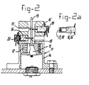
- the embodiment of Figure 2 comprises a housing 11 with a foot 14 for attaching the housing to the body of the spacecraft.
- a spring 12 is positioned which in the operating condition of the system is tensioning the cable 13 coming out of the system.
- the cable 13 ends into a holding element 15 in the foot of the housing.
- the difference between the free length of the spring and the completely compressed length thereof is such that, taking into account the elastical stretch and creep of the wire material and the increase of length at the rupture position during the heating of the cable, a sufficient tension will be maintained into the wire until the moment of complete breakage.
- the housing 11 comprises two or more electrical heating elements 16, 16' which are ' maintained in contact with the cable at the rupture positions 17, 18 to be able to supply locally a concentrated amount of heating energy.
- each heating element is pressed by a spring 19, 20 against said cable, whereby in combination with the cable tension such a contact pressure is obtained that a very good and very local energy transfer from each element to the cable 13 is realized.
- Figure 2a illustrates how the front part of each of the heating elements 16,16' is formed and how this part presses against the cable 13 at the rupture positions 17, 18.
- FIG 3 illustrates a second embodiment of the system according to the invention in which corresponding parts are indicated by the same reference numbers.
- the principal difference between this embodiment and the embodiment which was described with reference to Figure 2 is that the heating elements in this case are positioned such that they are forced to make contact with the tensioned cable. It is therefore necessary to install springs into each of the heating elements to guarantee a sufficient contact pressure.
- the embodiment of the holding element 15 differs from the embodiment in Figure 2.
- FIG. 3a illustrates the heating element in more detail.
- Figure 4 illustrates a third embodiment of the system according to the invention, similar to the embodiment in Figure 3, however, destined now for application onto a tensioned cable which is tensioned and connected independent of the device for breaking the cable in a further not illustrated way. Therefore in this embodiment the holding element and the spring cooperating therewith are deleted. By a correct positioning of the system the heating elements are forced to make contact with the connecting cable.
- heating element is not in the first place necessary to let the wire come out of the system axially, but, and that applies to all three illustrated embodiments, to decrease the chance of failure of the system. If unexpectedly the heating element, which was switched on first does not function properly, then there is still an element in reserve.
- the diameter of the cable for the device will be determined, besides by the combination of material properties, by the tension in the wire resulting from loads exerted by the system to which the cable is coupled. Determining material properties are: the specifical tensile strength, the specifical heat capacity, the creep characteristics, the specific weight, the change of the mechanical characteristics under thermal influences and the nature and amount of eventual decomposition products released when the material is degraded.
- the cable will be embodied such that there is an optical contact surface between the wire and the heating element.
- the term embodiment covers in this respect the form and fullness of the wire cross-section (round, flat, massive, tubular), and/or the composition of the wire as a strand or the composition out of a number of strands by spinning or twisting. With an optimum contact surface the energy transfer from the heating elements will be concentrated onto a small cross-section of the cable minimizing thereby the necessary energy for the breaking process so that a certain standard period until the moment of breakage can be defined per heating element.
- aramide fibers e.g. ° Kevlar 49
- Synthetic fibers are preferred above metal or glasseous fibers.
- the system according to the invention is destined in general to function only once within a predetermined program, within the scope of which program in general a very short time period is available for functioning of the system. From the standpoint of energy consumption it is furthermore desired to restrict the time period in which the system has to function. It is therefore preferred to select the power capacity of the heating means and/or the material characteristics of the connecting element such that after switching the heating means on the connecting element will break within a relatively short time period. A period of maximal several minutes, more especially a period shorter than one minute is preferred.
Landscapes
- Engineering & Computer Science (AREA)
- Remote Sensing (AREA)
- Aviation & Aerospace Engineering (AREA)
- Fuses (AREA)
- Perforating, Stamping-Out Or Severing By Means Other Than Cutting (AREA)
Description
- The-invention relates to a system for breaking a tensioned connecting element by means of which element until the moment of breakage parts of a construction, specially a space craft construction, are maintained in a predetermined position, which system comprises:
- a cable or similar element attached to two supporting elements of said construction maintaining thereby said parts of the construction in said predetermined position,
- means for breaking said cable or similar element releasing thereby at least one of said parts out of the predetermined position and
- tensioning means attached to said cable or similar element and providing a tension in said cable sufficient to displace at least one of the ruptured end parts of said cable out of reach of said breaking means after the cable is broken.
- Constructions of this type are extensively used in deployable and/or foldable constructions especially in or on space-crafts, such as solar panels, antennae, etc. By means of a system of locking elements, coupled to the tensioned connecting element, the folded construction is maintained in the locking situation until the connecting element is broken, whereafter the construction is released and is able to deploy. Such systems are also used for removable or rejectable covers on instruments on board of observation satellites.
- Usually space-crafts possess systems or parts thereof which only start functioning after the space-craft is brought into the space. During the transport from the earth to the position in space these systems are folded together and covered such that the volume thereof is restricted and that these parts are fixed and/or covered such that the chance that they become damaged during the transport of the space-craft from the earth to the position in space by mechanical and/or acoustical loads or by thermal or chemical influences is restricted to an acceptable minimum level, or the useful life of said parts is extended. For this purpose the construction concerned may be stowed into a box with a lid, or can comprise a rejectable cover whereby the lid or cover is coupled to a mechanism taking care of opening said lid or cover at the desired moment. It is also possible to realize a temporarily mechanical pretension of bearings.
- A system of the type mentioned in the preamble is known from the European patent application EP-A-0 059 673. In this known system the connection element is embodied as a wire or cable positioned between a fixed support element and a tensioned spring, of which the other end is connected to a further fixed support element. This pretensioned cable is coupled to a number of locking strips. At the moment of breakage of the cable, said cable will be shifted by means of the pretensioned spring tearing thereby the locking strips with the result that parts of the space-craft which until that moment were confined by said locking strips are released. In said European patent application nothing is said, however, about the method for breaking the tensioned cable.
- It is known from the prior art that a cable maintaining a spring in a pretensioned condition, can be broken by a mechanical cutting action, eventually activated explosively. This last method however, involves the risk, at least with space-crafts, that residual products of the explosive material will be deposited onto the space-craft or will become floating into the direct neighbourhood thereof influencing the functioning of certain systems thereby in a very negative way. In devices, in which in this respect measures are carried out to hold the residual products of the explosive material, after a shorter or longer time period corrosion appears which in itself involves a danger for the proper functioning of the space- craft. Therefore breaking methods whereby little or no harmful particles or gases are released, are preferred.
- An object of the invention is now to provide a system which does not have the above mentioned disadvantages.
- In agreement with said object the invention provides now a system of the type described in the preamble which is characterized in that the breaking means are embodied as at least two electrical heating elements connectable to an electrical power source and mounted in a frame attached to said construction, destined to break said cable under the influence of the electrically generated heat, said at least two heating elements being positioned in direct contact with the cable or similar element and are pressed towards the cable or similar element from radially opposed positions at a mutual distance of each other viewed in the longitudinal direction of the cable or similar element.
- By activating at least one of the electrical heating elements at the correct moment the strength of the material of the cable is degraded locally until such a level that the cable will break. In principle no moving parts are necessary.
- The U.S. Patent US-A-2,920,570 describes an arming device for a missile, projectile or the like, comprising a heating element for locally and with short duration heating of a cable made of cotton or nylon. In the non-activated condition the heating element is maintained at a distance from the cable by means of a spring and there is no contact between the heating element and the cable. The heating element, which is pivotably installed, is moved towards the cable under the influence of centrifugal force, developed by the spinning movement of the projectile after firing or launching said projectile. A spin actuated switch between the heater element and the electrical power source provides an energization delay of the heater element.
- To guarantee a good contact between the heating means and the connecting element it is preferred that the heating means are pressed against the cable by means of spring force.
- It is furthermore preferred that the cable or similar element at one end is clamped into a holding block under the influence of the tension in the cable or similar element is forced against an abutting surface of the frame. The advantage thereof is a very compact and very small construction in which the cable can be renewed very easily for instance after carrying out an operational test during the assembly of the space craft.
- It is furthermore preferred that a spring element is installed functioning between the holding block and the frame such that after breaking the cable the section thereof connected to the holding block is drawn out of the effective area of the heating elements.
- From the prior art it is known to use a cable made of cotton or nylon. However, these materials have a number of disadvantages such as spontaneous outgassing in vacuum conditions, spreading of solid or gaseous products. It is therefore preferred to make the cable or aramide fibers which do not show these disadvantages.
- In the following part of the description the invention will be discussed in more detail with reference to the attached drawings.
- Figure 1 illustrates the application of a tensioned connecting element for maintaining the cover onto a box until the moment of breakage.
- Figure 2 illustrates a first embodiment of a system according to the invention.
- Figure 3 illustrates a second embodiment of a system according to the invention.
- Figure 4 illustrates a third embodiment of the system according to the invention.
- Figure 1 illustrates a tensioned connecting element 1 embodied as a cable and applied to a box 2 with a cover 3. The tensioned connecting element is attached between a
support element 4 and a spring 5 and runs thereby e.g. over a rol 6. Alongside the tensioned connecting element thelocking strips 7, 8 are positioned by means of which the cover 3 is connected to the box 2. Near one end of the tensioned cable a device 9 is positioned for breaking the tensioned connecting element. When such a device is activated the cable will break and the spring 5 will draw the wire to one side tearing thereby the locking strips so that the cover 3 will be released from the box 2, which is the situation illustrated in the Figure. - In the Figures 2-4 three embodiments are illustrated of the device for breaking the cable.
- The embodiment of Figure 2 comprises a
housing 11 with afoot 14 for attaching the housing to the body of the spacecraft. In the foot 14 aspring 12 is positioned which in the operating condition of the system is tensioning thecable 13 coming out of the system. Thecable 13 ends into aholding element 15 in the foot of the housing. The difference between the free length of the spring and the completely compressed length thereof is such that, taking into account the elastical stretch and creep of the wire material and the increase of length at the rupture position during the heating of the cable, a sufficient tension will be maintained into the wire until the moment of complete breakage. Thehousing 11 comprises two or moreelectrical heating elements 16, 16' which are ' maintained in contact with the cable at therupture positions cable 13 is realized. - Figure 2a illustrates how the front part of each of the
heating elements 16,16' is formed and how this part presses against thecable 13 at therupture positions - Figure 3 illustrates a second embodiment of the system according to the invention in which corresponding parts are indicated by the same reference numbers. The principal difference between this embodiment and the embodiment which was described with reference to Figure 2 is that the heating elements in this case are positioned such that they are forced to make contact with the tensioned cable. It is therefore necessary to install springs into each of the heating elements to guarantee a sufficient contact pressure. Furthermore, the embodiment of the
holding element 15 differs from the embodiment in Figure 2. - Figure 3a illustrates the heating element in more detail.
- Figure 4 illustrates a third embodiment of the system according to the invention, similar to the embodiment in Figure 3, however, destined now for application onto a tensioned cable which is tensioned and connected independent of the device for breaking the cable in a further not illustrated way. Therefore in this embodiment the holding element and the spring cooperating therewith are deleted. By a correct positioning of the system the heating elements are forced to make contact with the connecting cable.
- The use of more than one heating element is not in the first place necessary to let the wire come out of the system axially, but, and that applies to all three illustrated embodiments, to decrease the chance of failure of the system. If unexpectedly the heating element, which was switched on first does not function properly, then there is still an element in reserve.
- After breakage of the cable at the
positions - In spacecraft applications such as communications satellites and earth observation satellites, the diameter of the cable for the device will be determined, besides by the combination of material properties, by the tension in the wire resulting from loads exerted by the system to which the cable is coupled. Determining material properties are: the specifical tensile strength, the specifical heat capacity, the creep characteristics, the specific weight, the change of the mechanical characteristics under thermal influences and the nature and amount of eventual decomposition products released when the material is degraded.
- Based on a certain diameter the cable will be embodied such that there is an optical contact surface between the wire and the heating element. The term embodiment covers in this respect the form and fullness of the wire cross-section (round, flat, massive, tubular), and/or the composition of the wire as a strand or the composition out of a number of strands by spinning or twisting. With an optimum contact surface the energy transfer from the heating elements will be concentrated onto a small cross-section of the cable minimizing thereby the necessary energy for the breaking process so that a certain standard period until the moment of breakage can be defined per heating element.
- After breakage of the wire no energy is withdrawn from the heating element and therefore the heat of the element will increase. This increase of heat can be used as a signal to switch off the energy supply to the system. For safety reasons a switch can be installed within the foot of the system which switch can be actuated by the therein present spring after breakage of the cable.
- Experiments have shown that aramide fibers (e.g. ° Kevlar 49) are very suitable for use in the system. Synthetic fibers are preferred above metal or glasseous fibers.
- It is observed that the system according to the invention, especially in spacecraft applications, is destined in general to function only once within a predetermined program, within the scope of which program in general a very short time period is available for functioning of the system. From the standpoint of energy consumption it is furthermore desired to restrict the time period in which the system has to function. It is therefore preferred to select the power capacity of the heating means and/or the material characteristics of the connecting element such that after switching the heating means on the connecting element will break within a relatively short time period. A period of maximal several minutes, more especially a period shorter than one minute is preferred.
Claims (6)
Applications Claiming Priority (2)
| Application Number | Priority Date | Filing Date | Title |
|---|---|---|---|
| NL8300788 | 1983-03-03 | ||
| NL8300788 | 1983-03-03 |
Publications (2)
| Publication Number | Publication Date |
|---|---|
| EP0121959A1 EP0121959A1 (en) | 1984-10-17 |
| EP0121959B1 true EP0121959B1 (en) | 1987-11-25 |
Family
ID=19841499
Family Applications (1)
| Application Number | Title | Priority Date | Filing Date |
|---|---|---|---|
| EP19840200302 Expired EP0121959B1 (en) | 1983-03-03 | 1984-02-29 | System for breaking a tensioned connecting element |
Country Status (4)
| Country | Link |
|---|---|
| US (1) | US4540873A (en) |
| EP (1) | EP0121959B1 (en) |
| JP (1) | JPH0692080B2 (en) |
| DE (1) | DE3467745D1 (en) |
Families Citing this family (31)
| Publication number | Priority date | Publication date | Assignee | Title |
|---|---|---|---|---|
| DE3615263A1 (en) * | 1986-05-06 | 1987-11-12 | Messerschmitt Boelkow Blohm | HOLDING DEVICE ON SPACER BODIES |
| FR2648199B1 (en) * | 1989-06-09 | 1991-09-27 | Aerospatiale | TEMPORARY LINK DEVICE, PARTICULARLY FOR ARTIFICIAL SATELLITE APPENDIX, AND METHOD FOR RELEASING SUCH A LINK |
| US5184328A (en) * | 1992-03-04 | 1993-02-02 | Navigation Technology Corporation | Underwater release mechanism |
| FR2714358B1 (en) * | 1993-12-24 | 1996-03-15 | Aerospatiale | Device for holding and releasing a structure such as a deployable structure on board a spacecraft. |
| US5536917A (en) * | 1994-06-23 | 1996-07-16 | Motorla, Inc. | Housing with integral thin film resistive snap-fits |
| US5452513A (en) * | 1994-06-29 | 1995-09-26 | Eric Hulsman | Suture cutter |
| DE69420735T2 (en) * | 1994-12-14 | 2000-03-02 | Fokker Space B.V., Leiden | System for holding and separating construction elements |
| US6227493B1 (en) * | 1999-04-06 | 2001-05-08 | Planetary Systems Corporation | Reusable, separable, structural connector assembly |
| US6168116B1 (en) | 1999-06-21 | 2001-01-02 | Trw Astro Aerospace | Shear tie device |
| DE10016067B4 (en) * | 2000-03-31 | 2009-10-15 | Maschinenfabrik Niehoff Gmbh & Co. Kg | Apparatus and method for sharpening wire ends |
| EP1193406B1 (en) * | 2000-09-20 | 2004-08-04 | Sener, Ingenieria Y Sistemas, S.A. | Remote activation mechanism for equipment regulated deployment or release |
| US7048746B2 (en) * | 2002-06-27 | 2006-05-23 | Warden Matthew P | Method and instrument for thermal suture cutting |
| US20050203546A1 (en) * | 2002-06-27 | 2005-09-15 | Van Wyk Robert A. | Method, apparatus, and kit for thermal suture cutting |
| US7699856B2 (en) * | 2002-06-27 | 2010-04-20 | Van Wyk Robert A | Method, apparatus, and kit for thermal suture cutting |
| US7278612B1 (en) | 2003-12-05 | 2007-10-09 | Lockheed Martin Corporation | Swaged cable deployment in space |
| US20050279890A1 (en) * | 2004-03-23 | 2005-12-22 | Walter Holemans | Latching separation system |
| DE102004056641B4 (en) * | 2004-07-01 | 2017-02-23 | Astrium Gmbh | Device for the detachable mounting of components |
| EP1612141B1 (en) * | 2004-07-01 | 2014-12-31 | Astrium GmbH | Device for the releasable holding of parts |
| US20100059503A1 (en) * | 2006-05-22 | 2010-03-11 | Victor Petrenko | Pulse Electrothermal Deicing Of Complex Shapes |
| KR101407243B1 (en) * | 2013-02-19 | 2014-06-13 | 조선대학교산학협력단 | Non-shock Holding and Release Mechanism using Heating Wire |
| US9546008B1 (en) * | 2014-06-17 | 2017-01-17 | The United States Of America As Represented By The Administrator Of The National Aeronautics And Space Administration | Miniature release mechanism or diminutive assembly for nanosatellite deployables (DANY) |
| EP3239059B1 (en) * | 2014-12-26 | 2019-10-16 | Kawasaki Jukogyo Kabushiki Kaisha | Separation device |
| NL2015387B1 (en) | 2015-09-02 | 2017-03-22 | Airbus Defence And Space Netherlands B V | Solar Panel with Flexible Optical Elements. |
| NL2016677B1 (en) | 2016-04-26 | 2017-11-07 | Airbus Defence And Space Netherlands B V | Solar Panel and Flexible Radiator for a Spacecraft. |
| FR3067766B1 (en) * | 2017-06-20 | 2019-07-26 | Centre National D'etudes Spatiales | CONNECTION SYSTEM, REVERSIBLE, SCREW-NUT |
| US10981679B2 (en) * | 2017-08-04 | 2021-04-20 | Rocket Lab Usa, Inc. | Satellite deployer door release mechanism |
| CN109515761B (en) * | 2018-12-29 | 2024-04-02 | 深圳航天东方红海特卫星有限公司 | Microminiature fuse cutter for spaceflight |
| FR3109928B1 (en) * | 2020-05-11 | 2022-04-22 | Centre Nat Etd Spatiales | Improved Nano-Satellite Deployment Device |
| CN112977885B (en) * | 2021-04-23 | 2023-06-23 | 中国科学院微小卫星创新研究院 | Elastic hot knife unlocking device |
| CN113479292B (en) * | 2021-07-13 | 2026-01-23 | 中国船舶重工集团公司第七一五研究所 | Fusion-breaking type underwater release device |
| EP4480833B1 (en) | 2023-06-20 | 2026-03-25 | Airbus Defence and Space, S.A. | Multiple hold down and release device for restraining and releasing a payload from a spacecraft, and methods to release a payload from a spacecraft and to install such a multiple hold down and release device |
Family Cites Families (10)
| Publication number | Priority date | Publication date | Assignee | Title |
|---|---|---|---|---|
| US2726706A (en) * | 1951-06-25 | 1955-12-13 | Gen Mills Inc | Hot wire welder |
| US2920570A (en) * | 1956-12-17 | 1960-01-12 | Albert E Martin | Safety and delay arming device |
| DE1535034A1 (en) * | 1963-05-11 | 1969-08-14 | Zinser Textilmaschinen Gmbh | Device for interrupting the thread feed in the event of thread breakage on spinning and twisting machines |
| US3159124A (en) * | 1964-04-27 | 1964-12-01 | Tek Matic Corp | Electrical thread-trimming device |
| JPS516771A (en) * | 1974-07-08 | 1976-01-20 | Honda Motor Co Ltd | KASOKUDOKENCHISOCHI |
| DE2853070C3 (en) * | 1978-12-08 | 1981-10-29 | Messerschmitt-Bölkow-Blohm GmbH, 8000 München | Hold-down system for deployable or unfoldable support elements on spacecraft |
| JPS569134A (en) * | 1979-07-06 | 1981-01-30 | Japax Inc | Method and apparatus for automatic insertion of wire electrode |
| JPS5675100U (en) * | 1979-11-16 | 1981-06-19 | ||
| FR2501155A1 (en) * | 1981-03-03 | 1982-09-10 | Aerospatiale | MECHANICAL RELEASE DEVICE FOR EXAMPLE FOR SATELLITE |
| US4430552A (en) * | 1981-07-29 | 1984-02-07 | Peterson David D | Thermal release device |
-
1984
- 1984-02-29 DE DE8484200302T patent/DE3467745D1/en not_active Expired
- 1984-02-29 EP EP19840200302 patent/EP0121959B1/en not_active Expired
- 1984-03-02 JP JP4027984A patent/JPH0692080B2/en not_active Expired - Fee Related
- 1984-03-02 US US06/585,890 patent/US4540873A/en not_active Expired - Lifetime
Also Published As
| Publication number | Publication date |
|---|---|
| DE3467745D1 (en) | 1988-01-07 |
| JPH0692080B2 (en) | 1994-11-16 |
| EP0121959A1 (en) | 1984-10-17 |
| JPS59219200A (en) | 1984-12-10 |
| US4540873A (en) | 1985-09-10 |
Similar Documents
| Publication | Publication Date | Title |
|---|---|---|
| US4540873A (en) | System for breaking a tensioned connecting element | |
| US5606889A (en) | Reusable initiator for use in triggering high-load actuators | |
| JP4688495B2 (en) | Apparatus and method for releasably joining elements | |
| EP2298648B1 (en) | Restraint and release device | |
| US5119555A (en) | Non-explosive separation device | |
| EP1202905B1 (en) | Reusable, separable, structural connector assembly and method for connecting two vehicles | |
| US6073914A (en) | Release apparatus for a holddown device | |
| US4779826A (en) | Mounting device for spacecraft | |
| US7396182B2 (en) | Non-explosive device for releasably securing components | |
| CZ131396A3 (en) | Cable clamp for vehicles | |
| CA2282028A1 (en) | Fire fighting apparatus with improved hose deployment and reloading | |
| CN113071719B (en) | Double-hot-cutter type compression and release mechanism | |
| JPH0124120B2 (en) | ||
| EP0716982B1 (en) | System for holding together and separating parts of a construction | |
| US5651296A (en) | Device for providing protection against debris produced by a pyro bolt cutter | |
| US4265418A (en) | Elongated inflatable structures for flying device bodies | |
| FR2627581A1 (en) | DEVICE FOR EXITING THE SPACER TUBE FROM A HOLLOW LOADED PROJECTILE | |
| CN214139005U (en) | Compressing and releasing device and spacecraft | |
| KR100235790B1 (en) | Electrical igniter of a pyrotechnical gas generator | |
| US6299105B1 (en) | Spacecraft with an environmentally released deployable structure | |
| JPH01249598A (en) | Fixing device for articulated assembly | |
| US4714216A (en) | Fin erecting mechanisms | |
| US5036769A (en) | Pyrofuze pin for ordnance activation | |
| CN117262255B (en) | Coupling mechanism and satellite suitable for satellite separation | |
| US6182573B1 (en) | Grenade attachment system |
Legal Events
| Date | Code | Title | Description |
|---|---|---|---|
| PUAI | Public reference made under article 153(3) epc to a published international application that has entered the european phase |
Free format text: ORIGINAL CODE: 0009012 |
|
| AK | Designated contracting states |
Designated state(s): DE FR GB IT |
|
| 17P | Request for examination filed |
Effective date: 19850219 |
|
| 17Q | First examination report despatched |
Effective date: 19860120 |
|
| GRAA | (expected) grant |
Free format text: ORIGINAL CODE: 0009210 |
|
| RAP1 | Party data changed (applicant data changed or rights of an application transferred) |
Owner name: FOKKER AIRCRAFT B.V. |
|
| AK | Designated contracting states |
Kind code of ref document: B1 Designated state(s): DE FR GB IT |
|
| REF | Corresponds to: |
Ref document number: 3467745 Country of ref document: DE Date of ref document: 19880107 |
|
| ITF | It: translation for a ep patent filed | ||
| ET | Fr: translation filed | ||
| PLBE | No opposition filed within time limit |
Free format text: ORIGINAL CODE: 0009261 |
|
| STAA | Information on the status of an ep patent application or granted ep patent |
Free format text: STATUS: NO OPPOSITION FILED WITHIN TIME LIMIT |
|
| 26N | No opposition filed | ||
| ITTA | It: last paid annual fee | ||
| REG | Reference to a national code |
Ref country code: GB Ref legal event code: 732E |
|
| REG | Reference to a national code |
Ref country code: FR Ref legal event code: TP |
|
| REG | Reference to a national code |
Ref country code: GB Ref legal event code: IF02 |
|
| PGFP | Annual fee paid to national office [announced via postgrant information from national office to epo] |
Ref country code: FR Payment date: 20030210 Year of fee payment: 20 |
|
| PGFP | Annual fee paid to national office [announced via postgrant information from national office to epo] |
Ref country code: GB Payment date: 20030226 Year of fee payment: 20 |
|
| PGFP | Annual fee paid to national office [announced via postgrant information from national office to epo] |
Ref country code: DE Payment date: 20030313 Year of fee payment: 20 |
|
| PG25 | Lapsed in a contracting state [announced via postgrant information from national office to epo] |
Ref country code: GB Free format text: LAPSE BECAUSE OF EXPIRATION OF PROTECTION Effective date: 20040228 |
|
| REG | Reference to a national code |
Ref country code: GB Ref legal event code: PE20 |