EP0121797A2 - Carbon composite article and method of making same - Google Patents
Carbon composite article and method of making same Download PDFInfo
- Publication number
- EP0121797A2 EP0121797A2 EP84102611A EP84102611A EP0121797A2 EP 0121797 A2 EP0121797 A2 EP 0121797A2 EP 84102611 A EP84102611 A EP 84102611A EP 84102611 A EP84102611 A EP 84102611A EP 0121797 A2 EP0121797 A2 EP 0121797A2
- Authority
- EP
- European Patent Office
- Prior art keywords
- substrate
- set forth
- fibers
- matrix
- article
- Prior art date
- Legal status (The legal status is an assumption and is not a legal conclusion. Google has not performed a legal analysis and makes no representation as to the accuracy of the status listed.)
- Granted
Links
- OKTJSMMVPCPJKN-UHFFFAOYSA-N Carbon Chemical compound [C] OKTJSMMVPCPJKN-UHFFFAOYSA-N 0.000 title claims abstract description 64
- 229910052799 carbon Inorganic materials 0.000 title claims abstract description 53
- 239000002131 composite material Substances 0.000 title claims abstract description 36
- 238000004519 manufacturing process Methods 0.000 title claims abstract description 12
- 239000000758 substrate Substances 0.000 claims abstract description 214
- 239000000835 fiber Substances 0.000 claims abstract description 126
- 238000000576 coating method Methods 0.000 claims abstract description 56
- 239000011248 coating agent Substances 0.000 claims abstract description 52
- 238000000034 method Methods 0.000 claims abstract description 52
- 239000000919 ceramic Substances 0.000 claims abstract description 28
- 150000004767 nitrides Chemical class 0.000 claims abstract description 28
- 239000002296 pyrolytic carbon Substances 0.000 claims abstract description 12
- 238000005229 chemical vapour deposition Methods 0.000 claims description 53
- HBMJWWWQQXIZIP-UHFFFAOYSA-N silicon carbide Chemical compound [Si+]#[C-] HBMJWWWQQXIZIP-UHFFFAOYSA-N 0.000 claims description 49
- 229910010271 silicon carbide Inorganic materials 0.000 claims description 49
- 239000000463 material Substances 0.000 claims description 48
- 239000011159 matrix material Substances 0.000 claims description 40
- 239000007789 gas Substances 0.000 claims description 35
- XUIMIQQOPSSXEZ-UHFFFAOYSA-N Silicon Chemical compound [Si] XUIMIQQOPSSXEZ-UHFFFAOYSA-N 0.000 claims description 22
- 229910052710 silicon Inorganic materials 0.000 claims description 22
- 239000010703 silicon Substances 0.000 claims description 22
- 229910052751 metal Inorganic materials 0.000 claims description 21
- 239000002184 metal Substances 0.000 claims description 21
- 238000009792 diffusion process Methods 0.000 claims description 16
- VNWKTOKETHGBQD-UHFFFAOYSA-N methane Chemical compound C VNWKTOKETHGBQD-UHFFFAOYSA-N 0.000 claims description 14
- 229920000049 Carbon (fiber) Polymers 0.000 claims description 11
- 229910052581 Si3N4 Inorganic materials 0.000 claims description 11
- 239000004917 carbon fiber Substances 0.000 claims description 11
- 229910002804 graphite Inorganic materials 0.000 claims description 11
- 239000010439 graphite Substances 0.000 claims description 11
- 238000010438 heat treatment Methods 0.000 claims description 11
- HQVNEWCFYHHQES-UHFFFAOYSA-N silicon nitride Chemical compound N12[Si]34N5[Si]62N3[Si]51N64 HQVNEWCFYHHQES-UHFFFAOYSA-N 0.000 claims description 11
- IJGRMHOSHXDMSA-UHFFFAOYSA-N Atomic nitrogen Chemical compound N#N IJGRMHOSHXDMSA-UHFFFAOYSA-N 0.000 claims description 10
- 229920000297 Rayon Polymers 0.000 claims description 8
- 238000000151 deposition Methods 0.000 claims description 8
- 239000002964 rayon Substances 0.000 claims description 8
- 229910044991 metal oxide Inorganic materials 0.000 claims description 7
- 150000004706 metal oxides Chemical class 0.000 claims description 7
- 239000005055 methyl trichlorosilane Substances 0.000 claims description 7
- JLUFWMXJHAVVNN-UHFFFAOYSA-N methyltrichlorosilane Chemical compound C[Si](Cl)(Cl)Cl JLUFWMXJHAVVNN-UHFFFAOYSA-N 0.000 claims description 7
- 229920002239 polyacrylonitrile Polymers 0.000 claims description 7
- IJOOHPMOJXWVHK-UHFFFAOYSA-N chlorotrimethylsilane Chemical compound C[Si](C)(C)Cl IJOOHPMOJXWVHK-UHFFFAOYSA-N 0.000 claims description 6
- 239000011148 porous material Substances 0.000 claims description 6
- 238000012546 transfer Methods 0.000 claims description 6
- 239000011230 binding agent Substances 0.000 claims description 5
- 229910052757 nitrogen Inorganic materials 0.000 claims description 5
- 210000002268 wool Anatomy 0.000 claims description 5
- ATUOYWHBWRKTHZ-UHFFFAOYSA-N Propane Chemical compound CCC ATUOYWHBWRKTHZ-UHFFFAOYSA-N 0.000 claims description 4
- QVGXLLKOCUKJST-UHFFFAOYSA-N atomic oxygen Chemical compound [O] QVGXLLKOCUKJST-UHFFFAOYSA-N 0.000 claims description 4
- 229910052760 oxygen Inorganic materials 0.000 claims description 4
- 239000001301 oxygen Substances 0.000 claims description 4
- -1 pyrolyzed wool Substances 0.000 claims description 4
- 229910052715 tantalum Inorganic materials 0.000 claims description 4
- GUVRBAGPIYLISA-UHFFFAOYSA-N tantalum atom Chemical compound [Ta] GUVRBAGPIYLISA-UHFFFAOYSA-N 0.000 claims description 4
- ZOXJGFHDIHLPTG-UHFFFAOYSA-N Boron Chemical compound [B] ZOXJGFHDIHLPTG-UHFFFAOYSA-N 0.000 claims description 3
- 239000004215 Carbon black (E152) Substances 0.000 claims description 3
- 229910052796 boron Inorganic materials 0.000 claims description 3
- 239000007795 chemical reaction product Substances 0.000 claims description 3
- 230000008021 deposition Effects 0.000 claims description 3
- LIKFHECYJZWXFJ-UHFFFAOYSA-N dimethyldichlorosilane Chemical compound C[Si](C)(Cl)Cl LIKFHECYJZWXFJ-UHFFFAOYSA-N 0.000 claims description 3
- 239000008187 granular material Substances 0.000 claims description 3
- 229930195733 hydrocarbon Natural products 0.000 claims description 3
- 150000002430 hydrocarbons Chemical class 0.000 claims description 3
- 229910021332 silicide Inorganic materials 0.000 claims description 3
- FVBUAEGBCNSCDD-UHFFFAOYSA-N silicide(4-) Chemical compound [Si-4] FVBUAEGBCNSCDD-UHFFFAOYSA-N 0.000 claims description 3
- 239000005051 trimethylchlorosilane Substances 0.000 claims description 3
- VXEGSRKPIUDPQT-UHFFFAOYSA-N 4-[4-(4-methoxyphenyl)piperazin-1-yl]aniline Chemical compound C1=CC(OC)=CC=C1N1CCN(C=2C=CC(N)=CC=2)CC1 VXEGSRKPIUDPQT-UHFFFAOYSA-N 0.000 claims description 2
- 239000001294 propane Substances 0.000 claims description 2
- 239000005049 silicon tetrachloride Substances 0.000 claims description 2
- VYPSYNLAJGMNEJ-UHFFFAOYSA-N Silicium dioxide Chemical compound O=[Si]=O VYPSYNLAJGMNEJ-UHFFFAOYSA-N 0.000 claims 4
- 229910052814 silicon oxide Inorganic materials 0.000 claims 4
- 230000001737 promoting effect Effects 0.000 claims 3
- QYEXBYZXHDUPRC-UHFFFAOYSA-N B#[Ti]#B Chemical compound B#[Ti]#B QYEXBYZXHDUPRC-UHFFFAOYSA-N 0.000 claims 2
- 229910033181 TiB2 Inorganic materials 0.000 claims 2
- BUMGIEFFCMBQDG-UHFFFAOYSA-N dichlorosilicon Chemical compound Cl[Si]Cl BUMGIEFFCMBQDG-UHFFFAOYSA-N 0.000 claims 2
- 229910052735 hafnium Inorganic materials 0.000 claims 2
- VBJZVLUMGGDVMO-UHFFFAOYSA-N hafnium atom Chemical compound [Hf] VBJZVLUMGGDVMO-UHFFFAOYSA-N 0.000 claims 2
- WFKWXMTUELFFGS-UHFFFAOYSA-N tungsten Chemical compound [W] WFKWXMTUELFFGS-UHFFFAOYSA-N 0.000 claims 2
- 229910052721 tungsten Inorganic materials 0.000 claims 2
- 239000010937 tungsten Substances 0.000 claims 2
- UHOVQNZJYSORNB-UHFFFAOYSA-N Benzene Chemical compound C1=CC=CC=C1 UHOVQNZJYSORNB-UHFFFAOYSA-N 0.000 claims 1
- OTMSDBZUPAUEDD-UHFFFAOYSA-N Ethane Chemical compound CC OTMSDBZUPAUEDD-UHFFFAOYSA-N 0.000 claims 1
- VGGSQFUCUMXWEO-UHFFFAOYSA-N Ethene Chemical compound C=C VGGSQFUCUMXWEO-UHFFFAOYSA-N 0.000 claims 1
- 239000005977 Ethylene Substances 0.000 claims 1
- HSFWRNGVRCDJHI-UHFFFAOYSA-N alpha-acetylene Natural products C#C HSFWRNGVRCDJHI-UHFFFAOYSA-N 0.000 claims 1
- 239000001273 butane Substances 0.000 claims 1
- VJIYRPVGAZXYBD-UHFFFAOYSA-N dibromosilane Chemical compound Br[SiH2]Br VJIYRPVGAZXYBD-UHFFFAOYSA-N 0.000 claims 1
- KBDJQNUZLNUGDS-UHFFFAOYSA-N dibromosilicon Chemical compound Br[Si]Br KBDJQNUZLNUGDS-UHFFFAOYSA-N 0.000 claims 1
- 125000002534 ethynyl group Chemical group [H]C#C* 0.000 claims 1
- 150000004820 halides Chemical class 0.000 claims 1
- IJDNQMDRQITEOD-UHFFFAOYSA-N n-butane Chemical compound CCCC IJDNQMDRQITEOD-UHFFFAOYSA-N 0.000 claims 1
- OFBQJSOFQDEBGM-UHFFFAOYSA-N n-pentane Natural products CCCCC OFBQJSOFQDEBGM-UHFFFAOYSA-N 0.000 claims 1
- 238000007493 shaping process Methods 0.000 claims 1
- AIFMYMZGQVTROK-UHFFFAOYSA-N silicon tetrabromide Chemical compound Br[Si](Br)(Br)Br AIFMYMZGQVTROK-UHFFFAOYSA-N 0.000 claims 1
- IBOKZQNMFSHYNQ-UHFFFAOYSA-N tribromosilane Chemical compound Br[SiH](Br)Br IBOKZQNMFSHYNQ-UHFFFAOYSA-N 0.000 claims 1
- 230000003628 erosive effect Effects 0.000 abstract description 7
- 239000011241 protective layer Substances 0.000 abstract description 3
- 239000010410 layer Substances 0.000 description 23
- 230000035945 sensitivity Effects 0.000 description 13
- 238000003754 machining Methods 0.000 description 10
- 238000012360 testing method Methods 0.000 description 10
- 239000011521 glass Substances 0.000 description 8
- 238000007689 inspection Methods 0.000 description 8
- 238000013461 design Methods 0.000 description 7
- 239000004744 fabric Substances 0.000 description 7
- 230000008595 infiltration Effects 0.000 description 7
- 238000001764 infiltration Methods 0.000 description 7
- 230000008569 process Effects 0.000 description 7
- 238000012545 processing Methods 0.000 description 7
- 239000002002 slurry Substances 0.000 description 7
- 230000006835 compression Effects 0.000 description 6
- 238000007906 compression Methods 0.000 description 6
- 230000007797 corrosion Effects 0.000 description 6
- 238000005260 corrosion Methods 0.000 description 6
- 239000011153 ceramic matrix composite Substances 0.000 description 5
- 239000012530 fluid Substances 0.000 description 5
- 239000011295 pitch Substances 0.000 description 5
- 239000000047 product Substances 0.000 description 5
- 230000035939 shock Effects 0.000 description 5
- 238000005336 cracking Methods 0.000 description 4
- 230000000694 effects Effects 0.000 description 4
- 230000007246 mechanism Effects 0.000 description 4
- 230000001464 adherent effect Effects 0.000 description 3
- 238000013459 approach Methods 0.000 description 3
- 229910010293 ceramic material Inorganic materials 0.000 description 3
- 238000011161 development Methods 0.000 description 3
- 230000018109 developmental process Effects 0.000 description 3
- 238000005516 engineering process Methods 0.000 description 3
- 238000011156 evaluation Methods 0.000 description 3
- 239000002657 fibrous material Substances 0.000 description 3
- 230000006872 improvement Effects 0.000 description 3
- 230000001590 oxidative effect Effects 0.000 description 3
- 238000009877 rendering Methods 0.000 description 3
- 238000004901 spalling Methods 0.000 description 3
- 239000007858 starting material Substances 0.000 description 3
- 239000000126 substance Substances 0.000 description 3
- ZDHXKXAHOVTTAH-UHFFFAOYSA-N trichlorosilane Chemical compound Cl[SiH](Cl)Cl ZDHXKXAHOVTTAH-UHFFFAOYSA-N 0.000 description 3
- 239000005052 trichlorosilane Substances 0.000 description 3
- 230000001133 acceleration Effects 0.000 description 2
- 150000001721 carbon Chemical class 0.000 description 2
- YGZSVWMBUCGDCV-UHFFFAOYSA-N chloro(methyl)silane Chemical compound C[SiH2]Cl YGZSVWMBUCGDCV-UHFFFAOYSA-N 0.000 description 2
- 238000002485 combustion reaction Methods 0.000 description 2
- 230000003247 decreasing effect Effects 0.000 description 2
- 230000007547 defect Effects 0.000 description 2
- 230000007613 environmental effect Effects 0.000 description 2
- 238000007654 immersion Methods 0.000 description 2
- 239000007788 liquid Substances 0.000 description 2
- 238000012986 modification Methods 0.000 description 2
- 230000004048 modification Effects 0.000 description 2
- 239000013618 particulate matter Substances 0.000 description 2
- 229920001568 phenolic resin Polymers 0.000 description 2
- 239000005011 phenolic resin Substances 0.000 description 2
- 230000002829 reductive effect Effects 0.000 description 2
- 229920005989 resin Polymers 0.000 description 2
- 239000011347 resin Substances 0.000 description 2
- 239000002153 silicon-carbon composite material Substances 0.000 description 2
- 239000007921 spray Substances 0.000 description 2
- KEVULXPMSYWRPQ-UHFFFAOYSA-N 1,2,3-trichloro-4-methylsiline Chemical compound CC1=CC=[Si](Cl)C(Cl)=C1Cl KEVULXPMSYWRPQ-UHFFFAOYSA-N 0.000 description 1
- KXGFMDJXCMQABM-UHFFFAOYSA-N 2-methoxy-6-methylphenol Chemical compound [CH]OC1=CC=CC([CH])=C1O KXGFMDJXCMQABM-UHFFFAOYSA-N 0.000 description 1
- 239000004593 Epoxy Substances 0.000 description 1
- 102100029203 F-box only protein 8 Human genes 0.000 description 1
- 101100334493 Homo sapiens FBXO8 gene Proteins 0.000 description 1
- BLRPTPMANUNPDV-UHFFFAOYSA-N Silane Chemical compound [SiH4] BLRPTPMANUNPDV-UHFFFAOYSA-N 0.000 description 1
- 238000004458 analytical method Methods 0.000 description 1
- 230000004888 barrier function Effects 0.000 description 1
- 239000011233 carbonaceous binding agent Substances 0.000 description 1
- 239000003575 carbonaceous material Substances 0.000 description 1
- 238000010000 carbonizing Methods 0.000 description 1
- 230000008859 change Effects 0.000 description 1
- 238000001311 chemical methods and process Methods 0.000 description 1
- 239000011294 coal tar pitch Substances 0.000 description 1
- 230000001427 coherent effect Effects 0.000 description 1
- 238000010276 construction Methods 0.000 description 1
- 230000006378 damage Effects 0.000 description 1
- 230000032798 delamination Effects 0.000 description 1
- MROCJMGDEKINLD-UHFFFAOYSA-N dichlorosilane Chemical compound Cl[SiH2]Cl MROCJMGDEKINLD-UHFFFAOYSA-N 0.000 description 1
- 238000001035 drying Methods 0.000 description 1
- 239000003733 fiber-reinforced composite Substances 0.000 description 1
- 238000011049 filling Methods 0.000 description 1
- 230000037406 food intake Effects 0.000 description 1
- 239000002803 fossil fuel Substances 0.000 description 1
- 239000007849 furan resin Substances 0.000 description 1
- 238000007496 glass forming Methods 0.000 description 1
- 230000002401 inhibitory effect Effects 0.000 description 1
- 229910052809 inorganic oxide Inorganic materials 0.000 description 1
- 238000011835 investigation Methods 0.000 description 1
- 238000011068 loading method Methods 0.000 description 1
- 150000001247 metal acetylides Chemical class 0.000 description 1
- 150000002739 metals Chemical class 0.000 description 1
- 238000000465 moulding Methods 0.000 description 1
- NJPPVKZQTLUDBO-UHFFFAOYSA-N novaluron Chemical compound C1=C(Cl)C(OC(F)(F)C(OC(F)(F)F)F)=CC=C1NC(=O)NC(=O)C1=C(F)C=CC=C1F NJPPVKZQTLUDBO-UHFFFAOYSA-N 0.000 description 1
- 230000003647 oxidation Effects 0.000 description 1
- 238000007254 oxidation reaction Methods 0.000 description 1
- 239000002245 particle Substances 0.000 description 1
- 239000011301 petroleum pitch Substances 0.000 description 1
- 239000011120 plywood Substances 0.000 description 1
- 239000002243 precursor Substances 0.000 description 1
- 230000000750 progressive effect Effects 0.000 description 1
- 230000001681 protective effect Effects 0.000 description 1
- 239000002994 raw material Substances 0.000 description 1
- 230000003014 reinforcing effect Effects 0.000 description 1
- 238000011160 research Methods 0.000 description 1
- 239000011435 rock Substances 0.000 description 1
- 239000004065 semiconductor Substances 0.000 description 1
- 229910000077 silane Inorganic materials 0.000 description 1
- FDNAPBUWERUEDA-UHFFFAOYSA-N silicon tetrachloride Chemical compound Cl[Si](Cl)(Cl)Cl FDNAPBUWERUEDA-UHFFFAOYSA-N 0.000 description 1
- 238000006467 substitution reaction Methods 0.000 description 1
- 230000033772 system development Effects 0.000 description 1
- 238000005979 thermal decomposition reaction Methods 0.000 description 1
- 238000002207 thermal evaporation Methods 0.000 description 1
- 230000035899 viability Effects 0.000 description 1
- 238000011179 visual inspection Methods 0.000 description 1
- 239000002759 woven fabric Substances 0.000 description 1
Images

Classifications
-
- F—MECHANICAL ENGINEERING; LIGHTING; HEATING; WEAPONS; BLASTING
- F16—ENGINEERING ELEMENTS AND UNITS; GENERAL MEASURES FOR PRODUCING AND MAINTAINING EFFECTIVE FUNCTIONING OF MACHINES OR INSTALLATIONS; THERMAL INSULATION IN GENERAL
- F16D—COUPLINGS FOR TRANSMITTING ROTATION; CLUTCHES; BRAKES
- F16D69/00—Friction linings; Attachment thereof; Selection of coacting friction substances or surfaces
- F16D69/02—Composition of linings ; Methods of manufacturing
- F16D69/023—Composite materials containing carbon and carbon fibres or fibres made of carbonizable material
-
- C—CHEMISTRY; METALLURGY
- C04—CEMENTS; CONCRETE; ARTIFICIAL STONE; CERAMICS; REFRACTORIES
- C04B—LIME, MAGNESIA; SLAG; CEMENTS; COMPOSITIONS THEREOF, e.g. MORTARS, CONCRETE OR LIKE BUILDING MATERIALS; ARTIFICIAL STONE; CERAMICS; REFRACTORIES; TREATMENT OF NATURAL STONE
- C04B35/00—Shaped ceramic products characterised by their composition; Ceramics compositions; Processing powders of inorganic compounds preparatory to the manufacturing of ceramic products
- C04B35/01—Shaped ceramic products characterised by their composition; Ceramics compositions; Processing powders of inorganic compounds preparatory to the manufacturing of ceramic products based on oxide ceramics
- C04B35/14—Shaped ceramic products characterised by their composition; Ceramics compositions; Processing powders of inorganic compounds preparatory to the manufacturing of ceramic products based on oxide ceramics based on silica
-
- C—CHEMISTRY; METALLURGY
- C04—CEMENTS; CONCRETE; ARTIFICIAL STONE; CERAMICS; REFRACTORIES
- C04B—LIME, MAGNESIA; SLAG; CEMENTS; COMPOSITIONS THEREOF, e.g. MORTARS, CONCRETE OR LIKE BUILDING MATERIALS; ARTIFICIAL STONE; CERAMICS; REFRACTORIES; TREATMENT OF NATURAL STONE
- C04B35/00—Shaped ceramic products characterised by their composition; Ceramics compositions; Processing powders of inorganic compounds preparatory to the manufacturing of ceramic products
- C04B35/515—Shaped ceramic products characterised by their composition; Ceramics compositions; Processing powders of inorganic compounds preparatory to the manufacturing of ceramic products based on non-oxide ceramics
- C04B35/56—Shaped ceramic products characterised by their composition; Ceramics compositions; Processing powders of inorganic compounds preparatory to the manufacturing of ceramic products based on non-oxide ceramics based on carbides or oxycarbides
- C04B35/565—Shaped ceramic products characterised by their composition; Ceramics compositions; Processing powders of inorganic compounds preparatory to the manufacturing of ceramic products based on non-oxide ceramics based on carbides or oxycarbides based on silicon carbide
- C04B35/571—Shaped ceramic products characterised by their composition; Ceramics compositions; Processing powders of inorganic compounds preparatory to the manufacturing of ceramic products based on non-oxide ceramics based on carbides or oxycarbides based on silicon carbide obtained from Si-containing polymer precursors or organosilicon monomers
-
- C—CHEMISTRY; METALLURGY
- C04—CEMENTS; CONCRETE; ARTIFICIAL STONE; CERAMICS; REFRACTORIES
- C04B—LIME, MAGNESIA; SLAG; CEMENTS; COMPOSITIONS THEREOF, e.g. MORTARS, CONCRETE OR LIKE BUILDING MATERIALS; ARTIFICIAL STONE; CERAMICS; REFRACTORIES; TREATMENT OF NATURAL STONE
- C04B35/00—Shaped ceramic products characterised by their composition; Ceramics compositions; Processing powders of inorganic compounds preparatory to the manufacturing of ceramic products
- C04B35/515—Shaped ceramic products characterised by their composition; Ceramics compositions; Processing powders of inorganic compounds preparatory to the manufacturing of ceramic products based on non-oxide ceramics
- C04B35/56—Shaped ceramic products characterised by their composition; Ceramics compositions; Processing powders of inorganic compounds preparatory to the manufacturing of ceramic products based on non-oxide ceramics based on carbides or oxycarbides
- C04B35/565—Shaped ceramic products characterised by their composition; Ceramics compositions; Processing powders of inorganic compounds preparatory to the manufacturing of ceramic products based on non-oxide ceramics based on carbides or oxycarbides based on silicon carbide
- C04B35/573—Shaped ceramic products characterised by their composition; Ceramics compositions; Processing powders of inorganic compounds preparatory to the manufacturing of ceramic products based on non-oxide ceramics based on carbides or oxycarbides based on silicon carbide obtained by reaction sintering or recrystallisation
-
- C—CHEMISTRY; METALLURGY
- C04—CEMENTS; CONCRETE; ARTIFICIAL STONE; CERAMICS; REFRACTORIES
- C04B—LIME, MAGNESIA; SLAG; CEMENTS; COMPOSITIONS THEREOF, e.g. MORTARS, CONCRETE OR LIKE BUILDING MATERIALS; ARTIFICIAL STONE; CERAMICS; REFRACTORIES; TREATMENT OF NATURAL STONE
- C04B35/00—Shaped ceramic products characterised by their composition; Ceramics compositions; Processing powders of inorganic compounds preparatory to the manufacturing of ceramic products
- C04B35/515—Shaped ceramic products characterised by their composition; Ceramics compositions; Processing powders of inorganic compounds preparatory to the manufacturing of ceramic products based on non-oxide ceramics
- C04B35/58—Shaped ceramic products characterised by their composition; Ceramics compositions; Processing powders of inorganic compounds preparatory to the manufacturing of ceramic products based on non-oxide ceramics based on borides, nitrides, i.e. nitrides, oxynitrides, carbonitrides or oxycarbonitrides or silicides
- C04B35/5805—Shaped ceramic products characterised by their composition; Ceramics compositions; Processing powders of inorganic compounds preparatory to the manufacturing of ceramic products based on non-oxide ceramics based on borides, nitrides, i.e. nitrides, oxynitrides, carbonitrides or oxycarbonitrides or silicides based on borides
- C04B35/58064—Shaped ceramic products characterised by their composition; Ceramics compositions; Processing powders of inorganic compounds preparatory to the manufacturing of ceramic products based on non-oxide ceramics based on borides, nitrides, i.e. nitrides, oxynitrides, carbonitrides or oxycarbonitrides or silicides based on borides based on refractory borides
- C04B35/58071—Shaped ceramic products characterised by their composition; Ceramics compositions; Processing powders of inorganic compounds preparatory to the manufacturing of ceramic products based on non-oxide ceramics based on borides, nitrides, i.e. nitrides, oxynitrides, carbonitrides or oxycarbonitrides or silicides based on borides based on refractory borides based on titanium borides
-
- C—CHEMISTRY; METALLURGY
- C04—CEMENTS; CONCRETE; ARTIFICIAL STONE; CERAMICS; REFRACTORIES
- C04B—LIME, MAGNESIA; SLAG; CEMENTS; COMPOSITIONS THEREOF, e.g. MORTARS, CONCRETE OR LIKE BUILDING MATERIALS; ARTIFICIAL STONE; CERAMICS; REFRACTORIES; TREATMENT OF NATURAL STONE
- C04B35/00—Shaped ceramic products characterised by their composition; Ceramics compositions; Processing powders of inorganic compounds preparatory to the manufacturing of ceramic products
- C04B35/515—Shaped ceramic products characterised by their composition; Ceramics compositions; Processing powders of inorganic compounds preparatory to the manufacturing of ceramic products based on non-oxide ceramics
- C04B35/58—Shaped ceramic products characterised by their composition; Ceramics compositions; Processing powders of inorganic compounds preparatory to the manufacturing of ceramic products based on non-oxide ceramics based on borides, nitrides, i.e. nitrides, oxynitrides, carbonitrides or oxycarbonitrides or silicides
- C04B35/584—Shaped ceramic products characterised by their composition; Ceramics compositions; Processing powders of inorganic compounds preparatory to the manufacturing of ceramic products based on non-oxide ceramics based on borides, nitrides, i.e. nitrides, oxynitrides, carbonitrides or oxycarbonitrides or silicides based on silicon nitride
- C04B35/589—Shaped ceramic products characterised by their composition; Ceramics compositions; Processing powders of inorganic compounds preparatory to the manufacturing of ceramic products based on non-oxide ceramics based on borides, nitrides, i.e. nitrides, oxynitrides, carbonitrides or oxycarbonitrides or silicides based on silicon nitride obtained from Si-containing polymer precursors or organosilicon monomers
-
- C—CHEMISTRY; METALLURGY
- C04—CEMENTS; CONCRETE; ARTIFICIAL STONE; CERAMICS; REFRACTORIES
- C04B—LIME, MAGNESIA; SLAG; CEMENTS; COMPOSITIONS THEREOF, e.g. MORTARS, CONCRETE OR LIKE BUILDING MATERIALS; ARTIFICIAL STONE; CERAMICS; REFRACTORIES; TREATMENT OF NATURAL STONE
- C04B35/00—Shaped ceramic products characterised by their composition; Ceramics compositions; Processing powders of inorganic compounds preparatory to the manufacturing of ceramic products
- C04B35/622—Forming processes; Processing powders of inorganic compounds preparatory to the manufacturing of ceramic products
- C04B35/626—Preparing or treating the powders individually or as batches ; preparing or treating macroscopic reinforcing agents for ceramic products, e.g. fibres; mechanical aspects section B
- C04B35/628—Coating the powders or the macroscopic reinforcing agents
- C04B35/62844—Coating fibres
- C04B35/62857—Coating fibres with non-oxide ceramics
- C04B35/6286—Carbides
- C04B35/62863—Silicon carbide
-
- C—CHEMISTRY; METALLURGY
- C04—CEMENTS; CONCRETE; ARTIFICIAL STONE; CERAMICS; REFRACTORIES
- C04B—LIME, MAGNESIA; SLAG; CEMENTS; COMPOSITIONS THEREOF, e.g. MORTARS, CONCRETE OR LIKE BUILDING MATERIALS; ARTIFICIAL STONE; CERAMICS; REFRACTORIES; TREATMENT OF NATURAL STONE
- C04B35/00—Shaped ceramic products characterised by their composition; Ceramics compositions; Processing powders of inorganic compounds preparatory to the manufacturing of ceramic products
- C04B35/622—Forming processes; Processing powders of inorganic compounds preparatory to the manufacturing of ceramic products
- C04B35/626—Preparing or treating the powders individually or as batches ; preparing or treating macroscopic reinforcing agents for ceramic products, e.g. fibres; mechanical aspects section B
- C04B35/628—Coating the powders or the macroscopic reinforcing agents
- C04B35/62844—Coating fibres
- C04B35/62857—Coating fibres with non-oxide ceramics
- C04B35/62865—Nitrides
- C04B35/62871—Silicon nitride
-
- C—CHEMISTRY; METALLURGY
- C04—CEMENTS; CONCRETE; ARTIFICIAL STONE; CERAMICS; REFRACTORIES
- C04B—LIME, MAGNESIA; SLAG; CEMENTS; COMPOSITIONS THEREOF, e.g. MORTARS, CONCRETE OR LIKE BUILDING MATERIALS; ARTIFICIAL STONE; CERAMICS; REFRACTORIES; TREATMENT OF NATURAL STONE
- C04B35/00—Shaped ceramic products characterised by their composition; Ceramics compositions; Processing powders of inorganic compounds preparatory to the manufacturing of ceramic products
- C04B35/622—Forming processes; Processing powders of inorganic compounds preparatory to the manufacturing of ceramic products
- C04B35/626—Preparing or treating the powders individually or as batches ; preparing or treating macroscopic reinforcing agents for ceramic products, e.g. fibres; mechanical aspects section B
- C04B35/628—Coating the powders or the macroscopic reinforcing agents
- C04B35/62844—Coating fibres
- C04B35/62857—Coating fibres with non-oxide ceramics
- C04B35/62873—Carbon
-
- C—CHEMISTRY; METALLURGY
- C04—CEMENTS; CONCRETE; ARTIFICIAL STONE; CERAMICS; REFRACTORIES
- C04B—LIME, MAGNESIA; SLAG; CEMENTS; COMPOSITIONS THEREOF, e.g. MORTARS, CONCRETE OR LIKE BUILDING MATERIALS; ARTIFICIAL STONE; CERAMICS; REFRACTORIES; TREATMENT OF NATURAL STONE
- C04B35/00—Shaped ceramic products characterised by their composition; Ceramics compositions; Processing powders of inorganic compounds preparatory to the manufacturing of ceramic products
- C04B35/622—Forming processes; Processing powders of inorganic compounds preparatory to the manufacturing of ceramic products
- C04B35/626—Preparing or treating the powders individually or as batches ; preparing or treating macroscopic reinforcing agents for ceramic products, e.g. fibres; mechanical aspects section B
- C04B35/628—Coating the powders or the macroscopic reinforcing agents
- C04B35/62884—Coating the powders or the macroscopic reinforcing agents by gas phase techniques
-
- C—CHEMISTRY; METALLURGY
- C04—CEMENTS; CONCRETE; ARTIFICIAL STONE; CERAMICS; REFRACTORIES
- C04B—LIME, MAGNESIA; SLAG; CEMENTS; COMPOSITIONS THEREOF, e.g. MORTARS, CONCRETE OR LIKE BUILDING MATERIALS; ARTIFICIAL STONE; CERAMICS; REFRACTORIES; TREATMENT OF NATURAL STONE
- C04B35/00—Shaped ceramic products characterised by their composition; Ceramics compositions; Processing powders of inorganic compounds preparatory to the manufacturing of ceramic products
- C04B35/71—Ceramic products containing macroscopic reinforcing agents
- C04B35/78—Ceramic products containing macroscopic reinforcing agents containing non-metallic materials
- C04B35/80—Fibres, filaments, whiskers, platelets, or the like
- C04B35/83—Carbon fibres in a carbon matrix
-
- C—CHEMISTRY; METALLURGY
- C04—CEMENTS; CONCRETE; ARTIFICIAL STONE; CERAMICS; REFRACTORIES
- C04B—LIME, MAGNESIA; SLAG; CEMENTS; COMPOSITIONS THEREOF, e.g. MORTARS, CONCRETE OR LIKE BUILDING MATERIALS; ARTIFICIAL STONE; CERAMICS; REFRACTORIES; TREATMENT OF NATURAL STONE
- C04B41/00—After-treatment of mortars, concrete, artificial stone or ceramics; Treatment of natural stone
- C04B41/009—After-treatment of mortars, concrete, artificial stone or ceramics; Treatment of natural stone characterised by the material treated
-
- C—CHEMISTRY; METALLURGY
- C04—CEMENTS; CONCRETE; ARTIFICIAL STONE; CERAMICS; REFRACTORIES
- C04B—LIME, MAGNESIA; SLAG; CEMENTS; COMPOSITIONS THEREOF, e.g. MORTARS, CONCRETE OR LIKE BUILDING MATERIALS; ARTIFICIAL STONE; CERAMICS; REFRACTORIES; TREATMENT OF NATURAL STONE
- C04B41/00—After-treatment of mortars, concrete, artificial stone or ceramics; Treatment of natural stone
- C04B41/45—Coating or impregnating, e.g. injection in masonry, partial coating of green or fired ceramics, organic coating compositions for adhering together two concrete elements
- C04B41/50—Coating or impregnating, e.g. injection in masonry, partial coating of green or fired ceramics, organic coating compositions for adhering together two concrete elements with inorganic materials
- C04B41/5053—Coating or impregnating, e.g. injection in masonry, partial coating of green or fired ceramics, organic coating compositions for adhering together two concrete elements with inorganic materials non-oxide ceramics
- C04B41/5057—Carbides
- C04B41/5059—Silicon carbide
-
- C—CHEMISTRY; METALLURGY
- C04—CEMENTS; CONCRETE; ARTIFICIAL STONE; CERAMICS; REFRACTORIES
- C04B—LIME, MAGNESIA; SLAG; CEMENTS; COMPOSITIONS THEREOF, e.g. MORTARS, CONCRETE OR LIKE BUILDING MATERIALS; ARTIFICIAL STONE; CERAMICS; REFRACTORIES; TREATMENT OF NATURAL STONE
- C04B41/00—After-treatment of mortars, concrete, artificial stone or ceramics; Treatment of natural stone
- C04B41/45—Coating or impregnating, e.g. injection in masonry, partial coating of green or fired ceramics, organic coating compositions for adhering together two concrete elements
- C04B41/50—Coating or impregnating, e.g. injection in masonry, partial coating of green or fired ceramics, organic coating compositions for adhering together two concrete elements with inorganic materials
- C04B41/5053—Coating or impregnating, e.g. injection in masonry, partial coating of green or fired ceramics, organic coating compositions for adhering together two concrete elements with inorganic materials non-oxide ceramics
- C04B41/5062—Borides, Nitrides or Silicides
- C04B41/5066—Silicon nitride
-
- C—CHEMISTRY; METALLURGY
- C04—CEMENTS; CONCRETE; ARTIFICIAL STONE; CERAMICS; REFRACTORIES
- C04B—LIME, MAGNESIA; SLAG; CEMENTS; COMPOSITIONS THEREOF, e.g. MORTARS, CONCRETE OR LIKE BUILDING MATERIALS; ARTIFICIAL STONE; CERAMICS; REFRACTORIES; TREATMENT OF NATURAL STONE
- C04B41/00—After-treatment of mortars, concrete, artificial stone or ceramics; Treatment of natural stone
- C04B41/80—After-treatment of mortars, concrete, artificial stone or ceramics; Treatment of natural stone of only ceramics
- C04B41/81—Coating or impregnation
- C04B41/85—Coating or impregnation with inorganic materials
- C04B41/87—Ceramics
-
- C—CHEMISTRY; METALLURGY
- C22—METALLURGY; FERROUS OR NON-FERROUS ALLOYS; TREATMENT OF ALLOYS OR NON-FERROUS METALS
- C22C—ALLOYS
- C22C49/00—Alloys containing metallic or non-metallic fibres or filaments
- C22C49/02—Alloys containing metallic or non-metallic fibres or filaments characterised by the matrix material
- C22C49/10—Refractory metals
-
- C—CHEMISTRY; METALLURGY
- C04—CEMENTS; CONCRETE; ARTIFICIAL STONE; CERAMICS; REFRACTORIES
- C04B—LIME, MAGNESIA; SLAG; CEMENTS; COMPOSITIONS THEREOF, e.g. MORTARS, CONCRETE OR LIKE BUILDING MATERIALS; ARTIFICIAL STONE; CERAMICS; REFRACTORIES; TREATMENT OF NATURAL STONE
- C04B2235/00—Aspects relating to ceramic starting mixtures or sintered ceramic products
- C04B2235/02—Composition of constituents of the starting material or of secondary phases of the final product
- C04B2235/30—Constituents and secondary phases not being of a fibrous nature
- C04B2235/38—Non-oxide ceramic constituents or additives
- C04B2235/3817—Carbides
- C04B2235/3826—Silicon carbides
-
- C—CHEMISTRY; METALLURGY
- C04—CEMENTS; CONCRETE; ARTIFICIAL STONE; CERAMICS; REFRACTORIES
- C04B—LIME, MAGNESIA; SLAG; CEMENTS; COMPOSITIONS THEREOF, e.g. MORTARS, CONCRETE OR LIKE BUILDING MATERIALS; ARTIFICIAL STONE; CERAMICS; REFRACTORIES; TREATMENT OF NATURAL STONE
- C04B2235/00—Aspects relating to ceramic starting mixtures or sintered ceramic products
- C04B2235/02—Composition of constituents of the starting material or of secondary phases of the final product
- C04B2235/30—Constituents and secondary phases not being of a fibrous nature
- C04B2235/42—Non metallic elements added as constituents or additives, e.g. sulfur, phosphor, selenium or tellurium
- C04B2235/422—Carbon
- C04B2235/425—Graphite
-
- C—CHEMISTRY; METALLURGY
- C04—CEMENTS; CONCRETE; ARTIFICIAL STONE; CERAMICS; REFRACTORIES
- C04B—LIME, MAGNESIA; SLAG; CEMENTS; COMPOSITIONS THEREOF, e.g. MORTARS, CONCRETE OR LIKE BUILDING MATERIALS; ARTIFICIAL STONE; CERAMICS; REFRACTORIES; TREATMENT OF NATURAL STONE
- C04B2235/00—Aspects relating to ceramic starting mixtures or sintered ceramic products
- C04B2235/02—Composition of constituents of the starting material or of secondary phases of the final product
- C04B2235/50—Constituents or additives of the starting mixture chosen for their shape or used because of their shape or their physical appearance
- C04B2235/52—Constituents or additives characterised by their shapes
- C04B2235/5208—Fibers
- C04B2235/5216—Inorganic
- C04B2235/524—Non-oxidic, e.g. borides, carbides, silicides or nitrides
- C04B2235/5248—Carbon, e.g. graphite
-
- C—CHEMISTRY; METALLURGY
- C04—CEMENTS; CONCRETE; ARTIFICIAL STONE; CERAMICS; REFRACTORIES
- C04B—LIME, MAGNESIA; SLAG; CEMENTS; COMPOSITIONS THEREOF, e.g. MORTARS, CONCRETE OR LIKE BUILDING MATERIALS; ARTIFICIAL STONE; CERAMICS; REFRACTORIES; TREATMENT OF NATURAL STONE
- C04B2235/00—Aspects relating to ceramic starting mixtures or sintered ceramic products
- C04B2235/60—Aspects relating to the preparation, properties or mechanical treatment of green bodies or pre-forms
- C04B2235/608—Green bodies or pre-forms with well-defined density
-
- C—CHEMISTRY; METALLURGY
- C04—CEMENTS; CONCRETE; ARTIFICIAL STONE; CERAMICS; REFRACTORIES
- C04B—LIME, MAGNESIA; SLAG; CEMENTS; COMPOSITIONS THEREOF, e.g. MORTARS, CONCRETE OR LIKE BUILDING MATERIALS; ARTIFICIAL STONE; CERAMICS; REFRACTORIES; TREATMENT OF NATURAL STONE
- C04B2235/00—Aspects relating to ceramic starting mixtures or sintered ceramic products
- C04B2235/60—Aspects relating to the preparation, properties or mechanical treatment of green bodies or pre-forms
- C04B2235/612—Machining
-
- C—CHEMISTRY; METALLURGY
- C04—CEMENTS; CONCRETE; ARTIFICIAL STONE; CERAMICS; REFRACTORIES
- C04B—LIME, MAGNESIA; SLAG; CEMENTS; COMPOSITIONS THEREOF, e.g. MORTARS, CONCRETE OR LIKE BUILDING MATERIALS; ARTIFICIAL STONE; CERAMICS; REFRACTORIES; TREATMENT OF NATURAL STONE
- C04B2235/00—Aspects relating to ceramic starting mixtures or sintered ceramic products
- C04B2235/60—Aspects relating to the preparation, properties or mechanical treatment of green bodies or pre-forms
- C04B2235/614—Gas infiltration of green bodies or pre-forms
-
- C—CHEMISTRY; METALLURGY
- C04—CEMENTS; CONCRETE; ARTIFICIAL STONE; CERAMICS; REFRACTORIES
- C04B—LIME, MAGNESIA; SLAG; CEMENTS; COMPOSITIONS THEREOF, e.g. MORTARS, CONCRETE OR LIKE BUILDING MATERIALS; ARTIFICIAL STONE; CERAMICS; REFRACTORIES; TREATMENT OF NATURAL STONE
- C04B2235/00—Aspects relating to ceramic starting mixtures or sintered ceramic products
- C04B2235/60—Aspects relating to the preparation, properties or mechanical treatment of green bodies or pre-forms
- C04B2235/616—Liquid infiltration of green bodies or pre-forms
-
- C—CHEMISTRY; METALLURGY
- C04—CEMENTS; CONCRETE; ARTIFICIAL STONE; CERAMICS; REFRACTORIES
- C04B—LIME, MAGNESIA; SLAG; CEMENTS; COMPOSITIONS THEREOF, e.g. MORTARS, CONCRETE OR LIKE BUILDING MATERIALS; ARTIFICIAL STONE; CERAMICS; REFRACTORIES; TREATMENT OF NATURAL STONE
- C04B2235/00—Aspects relating to ceramic starting mixtures or sintered ceramic products
- C04B2235/65—Aspects relating to heat treatments of ceramic bodies such as green ceramics or pre-sintered ceramics, e.g. burning, sintering or melting processes
- C04B2235/656—Aspects relating to heat treatments of ceramic bodies such as green ceramics or pre-sintered ceramics, e.g. burning, sintering or melting processes characterised by specific heating conditions during heat treatment
- C04B2235/6562—Heating rate
-
- C—CHEMISTRY; METALLURGY
- C04—CEMENTS; CONCRETE; ARTIFICIAL STONE; CERAMICS; REFRACTORIES
- C04B—LIME, MAGNESIA; SLAG; CEMENTS; COMPOSITIONS THEREOF, e.g. MORTARS, CONCRETE OR LIKE BUILDING MATERIALS; ARTIFICIAL STONE; CERAMICS; REFRACTORIES; TREATMENT OF NATURAL STONE
- C04B2235/00—Aspects relating to ceramic starting mixtures or sintered ceramic products
- C04B2235/70—Aspects relating to sintered or melt-casted ceramic products
- C04B2235/80—Phases present in the sintered or melt-cast ceramic products other than the main phase
-
- C—CHEMISTRY; METALLURGY
- C04—CEMENTS; CONCRETE; ARTIFICIAL STONE; CERAMICS; REFRACTORIES
- C04B—LIME, MAGNESIA; SLAG; CEMENTS; COMPOSITIONS THEREOF, e.g. MORTARS, CONCRETE OR LIKE BUILDING MATERIALS; ARTIFICIAL STONE; CERAMICS; REFRACTORIES; TREATMENT OF NATURAL STONE
- C04B2235/00—Aspects relating to ceramic starting mixtures or sintered ceramic products
- C04B2235/70—Aspects relating to sintered or melt-casted ceramic products
- C04B2235/96—Properties of ceramic products, e.g. mechanical properties such as strength, toughness, wear resistance
- C04B2235/9607—Thermal properties, e.g. thermal expansion coefficient
Definitions
- the present invention relates generally to fibrous ceramic matrix composite articles and the method of making same. More particularly the invention relates to unique carbon-silicon composite articles for use in high temperature, hostile fluid environment.
- Ceramics as structural materials for advanced engineering materials applications has been recognized for many years.
- Advantages of ceramics and ceramic matrix composites include the following: high strength/weight ratio; high stiffness/weight ratio; tailorable properties and geometry; high temperature strength; resistant to thermal shock, impact, corrosion/erosion and fatigue.
- Typical properties of carbon/carbon composites which are brittle fiber/brittle matrix ceramic systems, are sufficient to meet most identified application requirements. They are tough and somewhat forgiving materials and data shows that although microcracking does occur at load levels below ultimate failure, subsequent loading to equal or lesser stress levels will not propagate these cracks. Fatigue life is almost infinite.
- Carbon/carbon composite brake systems are currently operational on F-14, F-16, Space Shuttle, and Concorde aircraft. Individual wheel sets are also under evaluation in commercial service on all heavy lift aircraft - 747, DC10, L-1011, and Airbus.
- tantalum fibers with a silicon nitride matrix were successful in increasing the Charpy impact strength of the composite from one half foot pound to three and one half foot pounds before any cracking occurred.
- Using graphite fibers in a glass matrix system demonstrated properties approximately equaling those of graphite epoxy at room temperature and even higher strengths at 550°C.
- Graphite fiber reinforced silicon/silicon carbide composite systems offer a unique potential of minimizing, if not overcoming many of the limitations of monolithic ceramics.
- fiber type and precursor as well as fiber volume, fabrication technique, thermal and CVD processing parameters and the effect of the related variables that might be used in solving these problems.
- thermal and CVD processing parameters and the effect of the related variables that might be used in solving these problems.
- the fiber reinforced composite is also suitable as a substrate for CVD silicon carbide; parts have been coated, recoated and satisfactorily machined with relative ease following coating. Additional applications under investigation for these systems are semiconductor diffusion furnace tubes, advanced non-nuclear power system components, chemical process and fossil fuel power generating equipment and hardware for geothermal systems.
- Flaw sensitivity and brittleness are intrinsic limitations of monolithic ceramics which do not appear subject of simple solutions. Because of these limitations, successful utilization of ceramics in structural applications will require a change in the basic failure mechanism of these materials as discussed in previous paragraphs. Flaw sensitive, brittle fracture -- typical_of monolithic ceramics -- results in catastrophic failure such as when a rock hits a pane of glass. Such a failure must be changed to a tough or tearing mechanism where an orderly disruption of individual materials in the system fail on a microstructural basis resulting in no catastrophy such as experienced when hitting a piece of plywood with a hammer. This type of impact resistance and lack of catastrophic failure is typical of most fiber reinforced resin systems and can also be made available in ceramic matrix systems.
- Carbon, glass and hybrid carbon/silicon/silicon carbide/silicon nitride composite systems have exhibited substantial improvements in toughness and lack the flaw sensitivity so common in monolithic ceramics.
- Specific combinations of fibers, matrices and processing must be utilized to meet identified application requirements. Fiber selection, volume fraction and orientation coupled with matrix selection and processing technology can be varied over wide ranges thus providing designers with a degree of freedom to match application requirements that were previously unavailable.
- the process of the present invention overcomes the prior art problems of monolithic ceramic flaw sensitivity, brittleness and catastrophic failure and provides a unique, tough, non-flaw sensitive fibrous ceramic matrix composite article which will resist thermal shock/stress and can be reproducibly, reliably and economically fabricated to net dimension.
- It is an object of the present invention to provide a unique composite article adapted for use in highly corrosive, erosive environments comprising a fiberous substrate, a metallic carbide, oxide or nitride compliant coating over the fibers of the substrate and an impermeable metallic carbide, oxide or nitride outer protective layer or seal coat formed about the periphery of the coated substrate.
- a pyrolytic carbon coating is first deposited by chemical vapor deposition (CVD) about each of the fibers in such a manner that each fiber is substantially encased in a non-adherent pyrolytic carbon casing and then a metallic carbide, oxide or nitride coating is applied over the coated fibers in such a manner that the fibers remain freely movable relative to the applied coatings.
- CVD chemical vapor deposition
- This CVD carbon casing also provides a mechanical interface for increasing the surface fracture energy of the composite structure thus resulting substantial toughness and flaw resistance.
- a composite article produced by a method comprising the steps of forming a starting substrate of selected fiber/pore volume fractions and pore structure from a multiplicity of high temperature fibers such as carbon selected from a group consisting of pyrolyzed wool, rayon, polyacrylonitrile and pitch fibers; suspending the starting substrate within a first controlled environment; forming an intermediate substrate by heating the starting substrate to a temperature of between approximately 1500°F and approximately 2200°F while exposing the starting substrate to a hydrocarbon gas to form a uniform layer of pyrolytic carbon about each of the fibers in the starting substrate; removing the intermediate substrate from said first controlled environment and forming it into a shaped substrate having the approximate shape desired of the end product composite article; supporting the shaped substrate in a second controlled environment while heating it to a temperature of between approximately 1350°F and approximately 2500°F while exposing the intermediate substrate to a gas containing carbon and silicon such as trichlorosilane to form a uniform layer of CV
- the composite article of the invention consists of a two or more phase system comprising a basic substrate of carbon fibrous and/or ceramic materials, a metallic carbide, oxide, boride or nitride layer over the fibers and matrix of the substrate and an impermeable carbide, oxide, boride or nitride protective layer formed over the entire periphery of the infiltrated substrate.
- An important feature of the article is the absence of a,strong bond between the fibers and the matrix system to reduce flaw sensitivity, increase surface fracture energy (toughness) and to accommodate the mismatch in expansion coefficient between the fibrous substrate and the carbide, oxide, boride or nitride protective and seal coat layers.
- the articles of the invention are well suited for a variety of applications including turbine rotors, turbine augmentor divergent flaps and Diesel engine pre-combustion chambers made up of a carbon fiber, carbon (resin and/or pitch char and/or CVD deposit) matrix component which has been preformed to a selected component net geometry.
- a carbon fiber, carbon (resin and/or pitch char and/or CVD deposit) matrix component which has been preformed to a selected component net geometry.
- Each of the substrate fibers is encased in a non-adherent, uniform, CVD type carbon case so as to promote good load transfer from fiber to fiber when the article is stressed. This also provides a mechanical interface for increasing the surface fracture energy of the composite structure, thus resulting in greater toughness and flaw resistance.
- the fibers, matrix and interstices of the article are coated with a metallic carbide, oxide, boride or nitride to form a continuous CVD carbide, oxide, boride or nitride case around each of the fibers.
- This treatment effectively imparts increased load transfer from fiber to fiber and protects the interstices of the substrate from oxidation.
- the article of this interim state with its substrate and concentric layers of carbon and/or metal carbide, oxide, boride or nitride remains quite porous. Therefore, to increase strength and to provide complete protection for use in high temperature oxidizing environments, subsequent infiltration of the porous substrate is controlled to deposit a thicker CVD metallic carbide, oxide, boride or nitride on the more deeply located fibers than on those near the surface. This effectively overcomes decreasing density gradients currently experienced with pyrolytic carbon infiltration. Following this an impermeable CVD metal carbide, oxide, boride or nitride is applied to seal the surface with a material whose expansion coefficient is compatible with that of the infiltration coating. The final article thus formed is remarkably stable and highly corrosion resistant even in extreme environments.
- This article 12 which is a test specimen, comprises a central section 14 made up of carbon felt, chopped fiber or macerated material.
- the test specimen is shown positioned within a processing apparatus 16, the details which will presently be described.
- a material layer 18 Surrounding the central section 14 is a material layer 18 comprising a woven carbon fibrous material such as carbon or graphite cloth commercially available from The Union Carbide Company and others.
- the individual fibers of the central section 14 material layer 18 are coated with a layer, or sheath, of CVD carbon and then with a layer of metal carbide oxide, boride or nitride. Finally, the entire surface of the test specimen is sealed with an outer layer of CVD metal carbide, oxide, boride or nitride which extends about the entire periphery of the article.
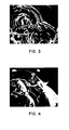
- Figure 3 is a reproduction of a photomicrograph of the coated fibrous material at 2000 times magnification.
- the fiber, the CVD coating about the fiber and the metal coating superimposed thereupon, are clearly visible.
- the ends of the individual fibers can clearly be seen protruding from the CVD carbon coating and the metal coating, in this case, metal carbide.
- a coating of metal oxide, boride or nitride would have a similar appearance.
- the metal coating be it an oxide, boride, nitride or a carbide
- the metal coating is applied to the fibers in a manner such that any mechanical stresses built up in the substrate due to a mismatch between the coefficients of thermal expansion of the fibrous substrate and the coating are effectively accommodated.
- the method of the invention stated in simple terms comprises the following steps: First, a multiplicity of high temperature fibers such as carbon fibers are assembled into a basic or starting substrate. This starting substrate is then heated to about 1000°F to about 3000°F in a controlled environment to thermally stabilize the substrate. Next the starting substrate is placed in a first controlled environment, heated to between about 1500°F and about 4200°F and exposed to a carbonaceous gas such as methane. During this step a uniform layer of CVD carbon is deposited about each of the fibers of the substrate. Following this step the interim substrate thus formed is machined or otherwise formed into the approximate shape of the end product.
- the shaped substrate formed in the previously described step is placed in a second controlled environment and heated to about 1350°F to about 2500°F.
- the heated shaped substrate is then exposed to a gas containing carbon and a metal, for example, silicon such as trichlorosilane for a period of time sufficient to form a uniform layer of CVD silicon carbide about each of the fibers/fiber bundles in either the starting or intermediate substrate.
- a metal for example, silicon such as trichlorosilane
- Other metals which can be deposited through chemical vapor deposition can also be used to form a metal coating selected from a group consisting of metal carbide, metal oxide, metal boride and metal nitride.
- the article thus formed is once again heated to a temperature of about 1800°F to about 3200°F in a third controlled environment and exposed to a gas containing carbon and silicon such as trichlorosilane.
- This step forms a uniform CVD seal coating of silicon carbide of controllable porosity about the entire periphery of the article.
- a starting substrate was constructed.
- the starting substrate was approximately 4 inches wide, 8 inches long and about 1 inch thick.
- the density of the substrate was on the order of 0.1 gm/cc and the fiber volume was about 7%.
- the starting substrate, along with several control specimens, was heated to about 1000°F to about 20QO°F for a period of time sufficient to thermally stabilize the substrate.
- the thermally stabilized substrate was then placed into a first vacuum-pressure controlled environment, which in this case was a vacuum chemical vapor deposition furnace of conventional design.
- the temperature of the substrate was then raised to about 1800°F while a vacuum of on the order of 15 mm Hg was maintained within the deposition chamber.
- a secondary, or intermediate, substrate was formed by controllably flowing methane gas interstitially of the substrate for a period of time of about 100 hours.
- methane gas interstitially of the substrate for a period of time of about 100 hours.
- a uniform layer of pyrolytic carbon was deposited about each of the fibers within the substrate to form an intermediate substrate having a density of on the order of 1.0 gm/cc.
- the intermediate substrate was cooled, removed from the vacuum furnace and transferred to a machining area.
- the intermediate substrate was machined in a conventional manner to form a shaped substrate.
- the shaped substrate was constructed in the configuration of a net dimension turbine augmentor divergent flap test section approximately 4 inches wide by 6 inches long by 1/2 inch thick.
- the divergent flap section, or shaped substrate was supported in a vacuum chamber, or second controlled environment as shown in Figure 1.
- the shaped substrate was then heated to about 1800°F in a mild vacuum. With the substrate at this elevated temperature a gas containing carbon and silicon was allowed to fill the chamber 22 to between 0.1 and .6 atmospheres. Following this back fill with a carbon and silicon containing gas the pressure of the chamber was then reduced to the original mild vacuum and this process repeated for a period of time of about fifty hours.
- the article 12 is supported upon a pedestal 24 disposed with a housing 26 which is open at its upper end 26a. With this arrangement a gas flow is achieved as depicted by the arrows of Figure 1 with the gas entering at 26 and exhausting at 28.
- the coated article thus formed was cooled, removed from the vacuum chamber and transferred to an inspection area.
- This inspection revealed that the diffusion coated article exhibited the dimensions of the shaped substrate within plus 0.0005 to 0.001 inches.
- Visual inspection of the control specimens which had been similarly processed showed the carbon fibers to be essentially unaffected by the methane or silane treatment.
- no strong bond was found to exist between the carbon fibers and the silicon carbide coating formed by coating the shaped substrate with the silicon carbide.
- no strong chemical or diffusion bonds were observed to exist between the fiber and/or matrix system. Accordingly, the fibers were free to move at a different rate from the carbon and/or silicon carbide matrix systems.
- This highly novel and important feature of the diffusion coated article of the present invention effectively minimizes any residual stresses tending to occur within the article. Furthermore, it provides an effective matrix system which permits the fibers to carry the load and be transferred from fiber to fiber through a continuous matrix irrespective of voids or other incipient flaws created by fiber spacing, crossover discontinuities or inclusions.
- a monolithic ceramic body processed in a comparable fashion to that just described would continue to exhibit significant flaw sensitivity.
- This residual intrinsic flaw sensitivity of monolithic ceramics results from an intimate intergranular bond which provides no means of inhibiting crack growth or decreasing surface fracture energy. Although adherent CVD overcoating tends to nullify the effects of surface defects, internal flaws and subcritical crack growth can result in extensive microcracking and subsequent catastrophic failure of the component.
- the infiltrated article was placed into a third controlled environment, or vacuum chemical vapor deposition furnace. Once in place within the CVD apparatus, the article was heated to about 1800°F and a gas containing dimethyldichlorosilane was controllably passed over and about the article. Due to the porous nature of the starting or pyrolytic carbon coated article formed by the novel method of the present invention, a uniform coating of CVD silicon carbide was deposited over the coated fibers of the article. This step provided an impermeable coating of silicon carbide over the fibers and interstices of the entire starting or intermediate substrate rendering it virtually impervious to corrosion and erosion caused by high temperatures and exposure to hostile gas and fluid environments. Subsequent testing and evaluation of the two phase CVD layer type coated article thus formed under extremely hostile environments showed it to be highly stable and remarkably resistant to flaw sensitivity, brittleness, catastrophic failure or thermally induced cracking, crazing or spalling.
- chopped fibers of carbonized polyacrylonitrile were used. This substrate was also about 4 inches wide, 8 inches long and about 1 inch thick. The fiber volume of the substrate was on the order of 35%.
- the starting substrate was placed into a vacuum furnace and the fibers thereof coated with pyrolytic carbon in the manner described in Example NO. 1.
- propane was used in lieu of methane as the carbonaceous gas.
- Example No. 1 After infiltration the substrate was removed from the CVD furnace and was machined into a shaped substrate in the manner of Example No. 1.
- the intermediate substrate was heated to about 1800°F in a second controlled environment maintained at slightly greater than atmospheric pressure and a CVD silicon carbide coating was deposited on the pyrolytic carbon coated fibers.
- the silicon coated article thus formed was dimensionally inspected and returned to the vacuum furnace wherein it was once again heated to about 1800°F. While being maintained at this elevated temperature a gas containing carbon and silicon, as for example trimethylchlorosilane was passed over and about the article to deposit a uniform coating of silicon carbide over the coated fibers and about the periphery of the article. The article thus formed was observed to have a small but measurable degree of open porosity.
- the metal coated article was sealed by introducing a metal oxide into the pores of the metal coated article. While the metal oxide in this example was in the form of fine particulate matter, the final coating could be accomplished by various methods including CVD, liquid spray or immersion.
- a carbonized rayon cloth made up of interwoven carbon fibers was cut into circular shaped pieces having a diameter of about 4 inches.
- a disc shaped starting substrate was constructed by stacking a plurality of the circular shaped pieces onto a base plate of a compression fixture. Each layer of cloth was rotated slightly with respect to the preceding layer and a top plate was placed over the assembly and bolted to the base plate. The assembly was then compressed to bring the cloth layers into intimate contact.
- the starting substrate thus formed exhibited a fiber volume of about 35% and a fiber density of about 1.4 gm/cc.
- the starting substrate along with the compression fixture, was placed into a CVD vacuum furnace and in the manner previously described, pyrolytic carbon was uniformly deposited over each of the fibers comprising the disc shaped starting substrate.
- the intermediate substrate thus formed was removed from the compression fixture and machined to form a disc about 3 1/2 inches in diameter and about 1 inch thick.
- the substrate was returned to the CVD vacuum furnace and heated to a temperature of about 1800°F.
- a gas containing methyltrichlorosilane was repeatedly passed over and about the shaped substrate for a period of time of about 50 hours to form a diffusion coated article in which a silicon carbide coating was formed about each of the coated fibers of the intermediate substrate.
- the temperature of the substrate was intermittently raised to about 2700°F to effect dimensional stability between the silicon carbide/pyrolytic carbon and the substrate.
- Example No. 1 After undergoing another dimensional inspection, the still porous, diffusion coated article was returned to the vacuum furnace for final coating with methyltrichlorosilane in the manner described in Example No. 1. Once again the two phase coated article thus formed exhibited remarkable stability and durability during severe environmental testing.
- a cylindrical shaped starting substrate was constructed by wrapping the tape about a mandrel. This substrate exhibited a density of about 0.83 gm/cc and a fiber volume of about 40%.
- This substrate was machined and then coated with silicon nitride as in Example No. 1 but using a dichlorosilane gas to form a diffusion coated substrate.
- the diffusion coated article thus formed was coated with a seal coat of silicon nitride by heating it under vacuum to a temperature of on the order of 1800°F and exposing it to a gas containing silicon and nitrogen as for example silicon chloride and nitrogen.
- This final step formed a uniform CVD coating of silicon nitride over the coated fibers and the periphery of the article rendering it virtually impervious to corrosion and erosion caused by high temperatures and exposure to hostile fluids.
- the starting material used was a macerated material comprising a multiplicity of randomly oriented pyrolyzed wool fibers. This starting material was formed into a substrate which was approximately 4 inches wide, 8 inches long and about 1 inch thick, and exhibited a fiber density of on the order of 35%.
- the starting substrate was processed in the manner described in Example No. I except that methyltrichlorosilane was used in applying the diffusion and final coating to the diffusion coated article.
- Example No. 1 Using a macerated material having a multiplicity of chopped pitch fibers a starting substrate which exhibited a fiber volume of about 60% was also processed as described in Example No. 1 save that silicon tetrachloride and methane were used in the diffusion and final coating steps.
- one form of the method of the invention involves encasing the substrate fibers in a CVD type carbon case. This encasement tends to promote good load transfer from fiber to fiber.
- load transfer characteristics can also be achieved by encasing the substrate fibers in one or more casings of silicon carbide. This can be accomplished by controllably flowing a gas such as dimethyldichloride or methyltrichlorosiline interstitially of the thermally stabilized substrate so as to form a uniform layer of pyrolytic silicon carbide about each of the fibers within the substrate.
- a gas such as dimethyldichloride or methyltrichlorosiline interstitially of the thermally stabilized substrate so as to form a uniform layer of pyrolytic silicon carbide about each of the fibers within the substrate.
- the starting substrate can advantageously be formed from a slurry comprising a granular material such as silicon carbide or graphite.
- the slurry can comprise such a granular material intermixed with short lengths of high temperature resistant fibers selected from the group consisting of ceramic, pyrolyzed wool, rayon, polyacrylonitrile and pitch.
- the slurry may also include a suitable carbonaceous binder such as petroleum pitch, coal tar pitch, furan resins and phenolic resins.
- Short lengths of rayon fibers were mixed with a suitable binder such as phenolic resin to form a slurry.
- the slurry was then vacuum formed into a formed substrate of the desired size and shape.
- the starting substrate was then produced by drying the formed substrate and carbonizing it at approximately 1200°C.
- the starting substrate, along with several control specimens, was heated to about 1000°F to about 2300°F for a period of time sufficient to thermally stabilize the substrate.
- the thermally stabilized substrate was then placed into a first vacuum-pressure controlled environment, which in this case was a vacuum chemical vapor deposition furnace of conventional design.
- the temperature of the substrate was then raised to about 1600-2200°F while a vacuum of on the order of 0.1 to 0.6 atmospheres was maintained within the deposition chamber.
- a secondary, or intermediate, substrate was formed by controllably flowing methylchlorosilane gas interstitially of the substrate for a period of time of about 20 hours.
- methylchlorosilane gas interstitially of the substrate for a period of time of about 20 hours.
- a uniform layer of pyrolytic silicon carbide was deposited about each of the fibers within the substrate to form an intermediate substrate having a density of on the order of 1.0 gm/cc.
- the intermediate substrate was cooled, removed from the vacuum furnace and transferred to a machining area.
- the intermediate substrate was machined in a conventional manner to form a shaped substrate of a desired configuration.
- the shaped substrate was supported in a vacuum chamber, or second controlled environment as shown in Figure 1.
- the shaped substrate was then heated to about 1600-2200°F in a mild vacuum. With the substrate at this elevated temperature a gas containing carbon and silicon was allowed to fill the chamber 22 to between 0.1 and .6 atmospheres. Following this back fill with a carbon and silicon containing gas the pressure of the chamber was then reduced to the original mild vacuum and this process repeated for a period of time of about fifty hours.
- the coated article thus formed was cooled, removed from the vacuum chamber and transferred to an inspection area.
- This inspection revealed that no strong bond was found to exist between the carbon fibers and the silicon carbide coating formed by coating the starting and shaped substrates with the silicon carbide.
- no strong chemical or diffusion bonds were observed to exist between the fiber and/or matrix system. Accordingly, the fibers were free to move at a different rate from the carbon and/or silicon carbide matrix systems.
- This highly novel and important feature of the diffusion coated article of the present invention effectively minimizes any residual stresses tending to occur within the article. Furthermore, it provides an effective matrix system which permits the fibers to carry the load and be transferred from fiber to fiber through a continuous matrix irrespective of voids or other incipient flaws created by fiber spacing, crossover discontinuities or inclusions.
- the infiltrated article was placed into a third controlled environment, or vacuum chemical vapor deposition furnace. Once in place within the CVD apparatus, the article was heated to about 1800°F and a gas containing demethyl- dichlorosilane was controllably passed over and about the article. Due to the porous nature of the starting or pyrolytic silicon carbide coated article formed by the novel method of the present invention, a uniform coating of CVD silicon carbide was deposited over the coated fibers of the article. This step provided an impermeable coating of silicon carbide over the fibers and interstices of the entire starting or intermediate substrate rendering it virtually impervious to corrosion and erosion caused by high temperatures and exposure to hostile gas and fluid environments. Subsequent testing and evaluation of the two phase CVD layer type coated article thus formed under extremely hostile environments showed it to be highly stable and remarkably resistant to flow sensitivity, brittleness, catastrophic failure or thermally induced cracking, crazing or spalling.
- the slurry used to form the starting substrate comprised short lengths of PAN fibers intermixed with silicon carbide in granular form.
- the slurry was vacuum formed into the desired shape and was then dried and carbonized at between 1200 and 1500°C.
- the starting substrate thus formed was placed into a vacuum furnace and the fibers thereof coated with pyrolytic silicon carbide in the manner described in Example No. 7.
- dimethyldichlorosilane was used in lieu of methyltrichlorosilane as the silicon bearing gas.
- Example No. 7 After infiltration the substrate was removed from the CVD furnace and was machined into a shaped substrate in the manner of Example No. 7.
- the intermediate substrate was heated to about 1800°F in a second controlled environment maintained at slightly greater than atmospheric pressure and a CVD silicon carbide coating was deposited on the pyrolytic silicon carbide coated fibers.
- the silicon coated article thus formed was dimensionally inspected and returned to the vacuum furnace wherein it was once again heated to about 1900°F. While being maintained at this elevated temperature a gas containing carbon and silicon, as for example trimethylchlorosilane was passed over and about the article to deposit a uniform coating of silicon carbide over the coated fibers and about the periphery of the article. The article thus formed was observed to have a small but measurable degree of open porosity.
- the metal coated article was sealed by introducing a metal oxide into the pores of the metal coated article. While the metal oxide in this example was in the form of fine particulate matter, the final coating could be accomplished by various methods including CVD, liquid spray or immersion.
- the starting substrate was constructed by molding granular graphite into a desired size and shape.
- the porous substrate thus formed was then carbonized and placed into a vacuum furnace where it was infiltrated with methylchlorosilane in accordance with the method of Example No. 7. In this way, a pyrolytic silicon carbide was deposited in and around the substrate to form an intermediate substrate.
- a carbonized rayon cloth made up of interwoven carbon fibers was cut into circular shaped pieces having a diameter of about 4 inches.
- a disc shaped starting substrate was constructed by stacking a plurality of the circular shaped pieces onto a base plate of a compression fixture. Each layer of cloth was rotated slightly with respect to the preceding layer and a top plate was placed over the assembly and bolted to the base plate. The assembly was then compressed to bring the cloth layers into intimate contact.
- the starting substrate thus formed exhibited a fiber volume of about 30 to 35% and a fiber density of about 1.5 gm/cc.
- the starting substrate along with the compression fixture, was placed into a CVD vacuum furnace and in the manner previously described, pyrolytic silicon carbide was uniformly deposited over each of the fibers comprising the disc shaped starting substrate.
- the intermediate substrate thus formed was removed from the compression fixture and machined to form a disc about 3 1/2 inches in diameter and about 1 inch thick.
- the substrate was returned to the CVD vacuum furnace and heated to a temperature of about 1600-2200°F.
- a gas containing methyltrichlorosilane was repeatedly passed over and about the shaped substrate for a period of time of about 50 hours to form a diffusion coated article in which a silicon carbide coating was formed about each of the coated fibers of the intermediate substrate.
- the temperature of the substrate was intermittently raised to about 2700°F to effect dimensional stability between the silicon carbide carbon fiber and the substrate.
- one basic method of the invention capable of being practiced by those skilled in the art after a study of the disclosures of Examples 7 through 10 comprises the steps of forming a starting substrate from a multiplicity of high temperature resistant fibers selected from a group consisting of ceramic, pyrolyzed wool, rayon, polyacrylonitrile and pitch fibers; exposing the starting substrate to an elevated temperature of about 1600-2200°F for a period of time sufficient to thermally stabilize the substrate; suspending the starting substrate within a first vacuum-pressure controlled environment; heating the starting substrate to a temperature of between approximately 1350°F and approximately 2500°F; and forming a coated article having a controlled degree of open porosity about the fibers of the starting substrate through chemical vapor deposition, a metal capable of reacting with carbon, oxygen, boron, silicon and nitrogen to form a carbide, oxide, boride, silicide and nitride.
- a metal capable of reacting with carbon, oxygen, boron, silicon and nitrogen to form a carbide, oxide, bor
- the fibers are uniquely free to move relative to the coatings. Accordingly the carbon-silicon composite article thus produced exhibits a high degree of dimensional stability and strength even under severe high temperature oxidizing conditions.
Landscapes
- Chemical & Material Sciences (AREA)
- Engineering & Computer Science (AREA)
- Ceramic Engineering (AREA)
- Materials Engineering (AREA)
- Organic Chemistry (AREA)
- Structural Engineering (AREA)
- Manufacturing & Machinery (AREA)
- Inorganic Chemistry (AREA)
- Chemical Kinetics & Catalysis (AREA)
- Mechanical Engineering (AREA)
- General Engineering & Computer Science (AREA)
- Composite Materials (AREA)
- Metallurgy (AREA)
- Chemical Vapour Deposition (AREA)
- Ceramic Products (AREA)
- Carbon And Carbon Compounds (AREA)
- Laminated Bodies (AREA)
Abstract
Description
- The present invention relates generally to fibrous ceramic matrix composite articles and the method of making same. More particularly the invention relates to unique carbon-silicon composite articles for use in high temperature, hostile fluid environment.
- The potential of ceramics as structural materials for advanced engineering materials applications has been recognized for many years. Advantages of ceramics and ceramic matrix composites include the following: high strength/weight ratio; high stiffness/weight ratio; tailorable properties and geometry; high temperature strength; resistant to thermal shock, impact, corrosion/erosion and fatigue.
- Experimental attempts to successfully demonstrate ceramic hardware, however, have not been completely successful due to flaw sensitivity, brittleness and catastrophic failure of the materials. In addition, other factors that have impeded utilization of advanced ceramic composites include: lack of proper designs and experience; thermal shock sensitivity; poor reproducibility, reliability; low impact strength; and high cost.
- Recent research efforts have improved materials and design methods. However, a more thorough and deeper understanding of their variations and behaivor is urgently required if ceramics are to be successfully utilized in the near term time frame. Unfortunately, the predominance of available ceramic materials only represent solutions looking for problems through substitution rationales rather than attacking their limitations directly. Current flaw sensitive, brittle failure mechanisms will have to be replaced by tough, high fracture energy materials whose failure mode is more forgiving and predictable.
- The only presently known methods of achieving practical high performance ceramic material systems is to introduce cohesive elements or barriers to crack propagation into a ceramic composite structure in the form of discrete particles or fibers; in other words, form a ceramic matrix composite. With such materials it is then possible to use an architectural approach to application design/material selection; identified operational requirements can then be matched with state-of-the-art materials and processes. Required work includes establishing specific performance and production criteria, careful design analysis and a goal-oriented, iterative materials development effort.
- State-of-the-art automotive gas turbines presently require an additional 500°F above their normal operating temperature to allow for acceleration of the rotating components. The use of ceramic for rotor and power train construction reduces mass and inertia by at least 50%, thereby reducing the acceleration over- temperature requirement to only 250°F available for steady state operation. This one-step improvement is equal to turbine operating temperature increases achieved through the past twenty-five years of metallurgical development.
- Such potential achievements realistically lie within the state-of-the-art of the technologies involved. However, intrinsic material properties and limitations have to be recognized and utilized within the design goal parameters. Raw materials, fabrication and processing techologies have to be interfaced with the designer and equipment operator to provide goal-oriented materials/ component/system development with prototype demonstration providing iterative feedback necessary to assure success.
- Typically all material strengths drop off ;<s temperatures increase. Since these rates of decrease, however, are not the same it provides designers with latitude in materials selection. The selection of materials for use at operating temperatures above 2000°F is quite limited and even at 2500°F silicon nitride and silicon carbide are on the down scope of their strength curve. On the other hand, carbon and its composites exhibit an equal or increase in strength from room temperature to more than 4000°F.
- Typical properties of carbon/carbon composites, which are brittle fiber/brittle matrix ceramic systems, are sufficient to meet most identified application requirements. They are tough and somewhat forgiving materials and data shows that although microcracking does occur at load levels below ultimate failure, subsequent loading to equal or lesser stress levels will not propagate these cracks. Fatigue life is almost infinite.
- A typical application for structural carbon/ carbon composite materials is found in aircraft brakes where the composite provides friction, heat sink and structural capabilities. Carbon/carbon composite brake systems are currently operational on F-14, F-16, Space Shuttle, and Concorde aircraft. Individual wheel sets are also under evaluation in commercial service on all heavy lift aircraft - 747, DC10, L-1011, and Airbus.
- In applying the theory of fracture mechanics to the thermal shock resistance of brittle materials, Rossi & Hasselman in their paper entitled "Application of Fracture-Mechanics Theory to the Thermal Shock Resistance of Brittle Materials" describe the values of increasing the surface fracture energy of a ceramic through the use of fiber reinforcing. Recent developments in graphite fiber reinforced carbon, silicon/silicon carbide and glass matrix composite systems have demonstrated viability in achieving this increase in surface fracture energy while allowing economical production of high strength intermediate/high temperature hardware that can be tailored to meet application requirements.
- Efforts with glass reinforced glass, tantalum reinforced silicon nitride and graphite/silicon carbide reinforced glass have shown that high strength, impact resistant, tough composite components can be readily fabricated. Additional prior art efforts have been shown that fibrous reinforced, net dimension ceramic composites can be produced free of pore sensitivity.
- The introduction of tantalum fibers with a silicon nitride matrix was successful in increasing the Charpy impact strength of the composite from one half foot pound to three and one half foot pounds before any cracking occurred. Using graphite fibers in a glass matrix system demonstrated properties approximately equaling those of graphite epoxy at room temperature and even higher strengths at 550°C.
- While it is well known that no chemical bonds exist in carbon/carbon systems, it is interesting to note that brittleness in these ceramic matrix composite systems appears to be a function of the fiber to matrix bond strength. In all cases, poor fiber to matrix bonds produce tough composites while good fiber to matrix bonds result in brittle, flaw sensitive materials.
- Graphite fiber reinforced silicon/silicon carbide composite systems offer a unique potential of minimizing, if not overcoming many of the limitations of monolithic ceramics. There are, however, a myriad of approaches which involve fiber type and precursor as well as fiber volume, fabrication technique, thermal and CVD processing parameters and the effect of the related variables that might be used in solving these problems. These approaches are based upon existing experience and manufacturing capabilities in carbon/carbon composite technology presently used for commercial aircraft brakes and a wide variety of thermostructural aerospace applications.
- The fiber reinforced composite is also suitable as a substrate for CVD silicon carbide; parts have been coated, recoated and satisfactorily machined with relative ease following coating. Additional applications under investigation for these systems are semiconductor diffusion furnace tubes, advanced non-nuclear power system components, chemical process and fossil fuel power generating equipment and hardware for geothermal systems.
- Flexural strengths of up to 120,000 PSI have been reported for carbon/silicon/silicon carbide material and early results with low fiber volume, low strength (approximately 10,000 PSI) radial turbine rotors show promise. A three inch radial turbine wheel with an integral shaft fabricated from a carbone/silicon/silicon carbide composite system was successfully spun at 50,000 RPM and 2,000°F. During its seven and one half hours of cyclical operation, seven starts and stops, including two flame-outs were experienced prior to test termination resulting from loss of tip clearance. Tip loss was caused by ingestion of foreign matter which adhered to the shroud and removed 5/16" of the blade tips while the rotor was operating at speed and temperature. Uniquely, and most importantly, this impact damage did not shatter the rotor or cause catastrophic failure; the turbine simply lost power due to loss of tip clearance and was shut down normally.
- Flaw sensitivity and brittleness are intrinsic limitations of monolithic ceramics which do not appear subject of simple solutions. Because of these limitations, successful utilization of ceramics in structural applications will require a change in the basic failure mechanism of these materials as discussed in previous paragraphs. Flaw sensitive, brittle fracture -- typical_of monolithic ceramics -- results in catastrophic failure such as when a rock hits a pane of glass. Such a failure must be changed to a tough or tearing mechanism where an orderly disruption of individual materials in the system fail on a microstructural basis resulting in no catastrophy such as experienced when hitting a piece of plywood with a hammer. This type of impact resistance and lack of catastrophic failure is typical of most fiber reinforced resin systems and can also be made available in ceramic matrix systems.
- Carbon, glass and hybrid carbon/silicon/silicon carbide/silicon nitride composite systems have exhibited substantial improvements in toughness and lack the flaw sensitivity so common in monolithic ceramics. Specific combinations of fibers, matrices and processing must be utilized to meet identified application requirements. Fiber selection, volume fraction and orientation coupled with matrix selection and processing technology can be varied over wide ranges thus providing designers with a degree of freedom to match application requirements that were previously unavailable.
- For the reasons previously discussed, great difficulty has been experienced in reproducibility and reliably manufacturing ceramic articles suitable for structural applications. One solution to the prior art difficulties is described in the co-pending application of the present inventor, Serial No. 62,401. The present invention comprises an improvement upon the methods and articles described in said co-pending application.
- As will be appreciated from the discussion which follows, the process of the present invention overcomes the prior art problems of monolithic ceramic flaw sensitivity, brittleness and catastrophic failure and provides a unique, tough, non-flaw sensitive fibrous ceramic matrix composite article which will resist thermal shock/stress and can be reproducibly, reliably and economically fabricated to net dimension.
- It is an object of the present invention to provide a unique composite article adapted for use in highly corrosive, erosive environments comprising a fiberous substrate, a metallic carbide, oxide or nitride compliant coating over the fibers of the substrate and an impermeable metallic carbide, oxide or nitride outer protective layer or seal coat formed about the periphery of the coated substrate.
- It is another object of the invention to provide a composite article of the aforementioned character which will substantially maintain its dimensional stability and strength even under severe high temperature oxidizing conditions.
- It is another object of the invention to provide a composite article of the class described which- is substantially resistant to corrosion and erosion by high temperature, hostile gas, particulate and fluid environments.
- It is an important object of the present invention to provide a composite article of the character described in the preceding paragraphs in which the aforementioned metallic carbide, oxide, boride or nitride coating is controllably applied to the carbon fibrous substrate in a manner such that any mechanical stresses built up in the substrate due to mismatches in coefficients of thermal expansion between the fiberous substrate and the coatings are effectively accommodated or relieved.
- It is another particularly important object of the present invention to provide a structural composite article of the character as described in the preceding paragraphs in which the aforementioned metallic carbide, oxide, boride or nitride coating is controllably applied to the carbon fiberous substrate in a manner such that any flaws or defects other than gross delaminations or inclusions will not initiate nor contribute to the propagation of microcracking which results in ultimate part failure; the part will have high fracture toughness and not subject to brittle failure typical of monolithic ceramics i.e. glass; and that ultimte failure is a tearing non-catastrophic failure where an orderly disruption of individual materials in the system fail on a progressive microstructural basis.
- It is a further important object of the present invention to provide a process for making composite articles of the character described in the preceding paragraphs in which the metallic carbide, oxide, boride or nitride coating is controllably applied to the carbon fibrous substrate in a manner such that the individual fibers of the substrate are free to move relative to the applied coating.
- More particularly, it is an object of the invention to provide a process as described in the previous paragraph in which a pyrolytic carbon coating is first deposited by chemical vapor deposition (CVD) about each of the fibers in such a manner that each fiber is substantially encased in a non-adherent pyrolytic carbon casing and then a metallic carbide, oxide or nitride coating is applied over the coated fibers in such a manner that the fibers remain freely movable relative to the applied coatings.
- It is another object of the invention to provide a composite article as described in the previous paragraph in which each fiber of the substrate is encased in a uniform CVD type carbon casing to promote superior load transfer from fiber to fiber when the article is stressed. This CVD carbon casing also provides a mechanical interface for increasing the surface fracture energy of the composite structure thus resulting substantial toughness and flaw resistance.
- It is still another object of the invention to provide a process of the aforementioned character in which, following the coating of the fibers, an impermeable carbide, nitride, boride or oxide coating is controllably formed about the fibers and entire periphery of the substrate to seal it against hostile environments.
- In summary, these and other objects of the invention are realized by a composite article produced by a method comprising the steps of forming a starting substrate of selected fiber/pore volume fractions and pore structure from a multiplicity of high temperature fibers such as carbon selected from a group consisting of pyrolyzed wool, rayon, polyacrylonitrile and pitch fibers; suspending the starting substrate within a first controlled environment; forming an intermediate substrate by heating the starting substrate to a temperature of between approximately 1500°F and approximately 2200°F while exposing the starting substrate to a hydrocarbon gas to form a uniform layer of pyrolytic carbon about each of the fibers in the starting substrate; removing the intermediate substrate from said first controlled environment and forming it into a shaped substrate having the approximate shape desired of the end product composite article; supporting the shaped substrate in a second controlled environment while heating it to a temperature of between approximately 1350°F and approximately 2500°F while exposing the intermediate substrate to a gas containing carbon and silicon such as trichlorosilane to form a uniform layer of CVD silicon carbide about each of the fibers/fiber bundles in either the starting or intermediate substrate.
-
- Figure 1 is a side elevational view of one form of controlled environment in which the substrate may be infiltrated and coated.
- Figure 2 is a generally diagrammatic view of a substrate showing diagrammatically the locations within the substrate at which the specimens shown in Figures 3 and 4 were taken.
- Figure 3 is a reproduction of a photomicrograph (2000x) taken at the edge of the substrate showing the appearance of the coated fibrous substrate at an intermediate density level and prior to the application of the final seal coat.
- Figure 4 is similar to Figure 3 showing a reproduction of a photomicrograph (2000x) taken at the center of the substrate and taken at the same intermediate processing stage.
- Before proceeding with a detailed discussion of the preferred embodiments of the present invention, the following definitions of the technical terms used herein are presented to facilitate a clear understanding of the nature and scope of the invention:
- 1. Composite product - a product comprising a carbon, graphite or ceramic substrate and one or more metallic carbide, oxide, boride or nitride coatings within or over the substrate material.
- 2. Starting or basic substrate - as used herein, the starting substrate or interim product shape before the application of a metallic coating.
- 3. Carbon fibrous substrate - a starting substrate comprising carbon material in fibrous form.
- 4. Fiber volume - volume % of carbon fibers present in the given substrate.
- 5. Non-woven - coherent fibrous material formed without interlacing of threads, such as batting or felt.
- 6. Woven - fabric formed by interlacing warp and filling threads on a loom, or the like.
- 7. Ceramic - metallic or other inorganic oxides, carbides, borides or nitrides generally classed as glass-forming oxides.
- 8. Pyrolytic or "CVD" material - a material made from the thermal decomposition of a gas containing the material.
- Stated in simple terms, the composite article of the invention consists of a two or more phase system comprising a basic substrate of carbon fibrous and/or ceramic materials, a metallic carbide, oxide, boride or nitride layer over the fibers and matrix of the substrate and an impermeable carbide, oxide, boride or nitride protective layer formed over the entire periphery of the infiltrated substrate. An important feature of the article is the absence of a,strong bond between the fibers and the matrix system to reduce flaw sensitivity, increase surface fracture energy (toughness) and to accommodate the mismatch in expansion coefficient between the fibrous substrate and the carbide, oxide, boride or nitride protective and seal coat layers.
- The articles of the invention are well suited for a variety of applications including turbine rotors, turbine augmentor divergent flaps and Diesel engine pre-combustion chambers made up of a carbon fiber, carbon (resin and/or pitch char and/or CVD deposit) matrix component which has been preformed to a selected component net geometry. Each of the substrate fibers is encased in a non-adherent, uniform, CVD type carbon case so as to promote good load transfer from fiber to fiber when the article is stressed. This also provides a mechanical interface for increasing the surface fracture energy of the composite structure, thus resulting in greater toughness and flaw resistance.
- Because carbon/carbon composites actively react with oxygen when heated to temperatures in excess of 300°C, the fibers, matrix and interstices of the article are coated with a metallic carbide, oxide, boride or nitride to form a continuous CVD carbide, oxide, boride or nitride case around each of the fibers. This treatment effectively imparts increased load transfer from fiber to fiber and protects the interstices of the substrate from oxidation. The lack of bond between the fiber and the carbon and the carbide, oxide, boride or nitride case, however, allows the carbon fibers and multi-phase matrix case to move independent of one another on a microscopic scale, thus overcoming flaw sensitivity and catastrophic failure, increasing surface fracture energy (toughness) and providing a compliance mechanism that effectively reduces thermally induced mechanical stresses. The appearance of the coated fibers is clearly illustrated in Figures 2 and 3 of the drawings.
- The article of this interim state with its substrate and concentric layers of carbon and/or metal carbide, oxide, boride or nitride remains quite porous. Therefore, to increase strength and to provide complete protection for use in high temperature oxidizing environments, subsequent infiltration of the porous substrate is controlled to deposit a thicker CVD metallic carbide, oxide, boride or nitride on the more deeply located fibers than on those near the surface. This effectively overcomes decreasing density gradients currently experienced with pyrolytic carbon infiltration. Following this an impermeable CVD metal carbide, oxide, boride or nitride is applied to seal the surface with a material whose expansion coefficient is compatible with that of the infiltration coating. The final article thus formed is remarkably stable and highly corrosion resistant even in extreme environments.
- Referring briefly to Figure 1 of the drawings, one form of article made by the method of the invention is there illustrated. This
article 12, which is a test specimen, comprises acentral section 14 made up of carbon felt, chopped fiber or macerated material. In Figure 1 the test specimen is shown positioned within aprocessing apparatus 16, the details which will presently be described. - Surrounding the
central section 14 is a material layer 18 comprising a woven carbon fibrous material such as carbon or graphite cloth commercially available from The Union Carbide Company and others. - In a manner which will be described in greater detail in the paragraphs which follow, the individual fibers of the
central section 14 material layer 18 are coated with a layer, or sheath, of CVD carbon and then with a layer of metal carbide oxide, boride or nitride. Finally, the entire surface of the test specimen is sealed with an outer layer of CVD metal carbide, oxide, boride or nitride which extends about the entire periphery of the article. - Referring to Figures 2 through 4, the character of the
coated substrate material 14 and 18 is there vividly illustrated. Figure 3 is a reproduction of a photomicrograph of the coated fibrous material at 2000 times magnification. In this Figure the fiber, the CVD coating about the fiber and the metal coating superimposed thereupon, are clearly visible. Also in this Figure the ends of the individual fibers can clearly be seen protruding from the CVD carbon coating and the metal coating, in this case, metal carbide. A coating of metal oxide, boride or nitride would have a similar appearance. As will be appreciated from the examples which follow, the metal coating, be it an oxide, boride, nitride or a carbide, is applied to the fibers in a manner such that any mechanical stresses built up in the substrate due to a mismatch between the coefficients of thermal expansion of the fibrous substrate and the coating are effectively accommodated. This important feature of the present invention is clearly illustrated in Figures 3 and 4 of the drawings. - It is to be appreciated that the article shown in Figures 2 through 4 of the drawings is merely exemplary of the type of article which can be made in accordance with the method of the present invention. Highly useful products of the invention include turbine rotors, diesel-engine combustion chambers, and numerous specially designed products for nuclear and aerospace applications.
- As will be clearly illustrated by the examples which follow, the method of the invention stated in simple terms comprises the following steps: First, a multiplicity of high temperature fibers such as carbon fibers are assembled into a basic or starting substrate. This starting substrate is then heated to about 1000°F to about 3000°F in a controlled environment to thermally stabilize the substrate. Next the starting substrate is placed in a first controlled environment, heated to between about 1500°F and about 4200°F and exposed to a carbonaceous gas such as methane. During this step a uniform layer of CVD carbon is deposited about each of the fibers of the substrate. Following this step the interim substrate thus formed is machined or otherwise formed into the approximate shape of the end product. Next the shaped substrate formed in the previously described step is placed in a second controlled environment and heated to about 1350°F to about 2500°F. The heated shaped substrate is then exposed to a gas containing carbon and a metal, for example, silicon such as trichlorosilane for a period of time sufficient to form a uniform layer of CVD silicon carbide about each of the fibers/fiber bundles in either the starting or intermediate substrate. Other metals which can be deposited through chemical vapor deposition can also be used to form a metal coating selected from a group consisting of metal carbide, metal oxide, metal boride and metal nitride. Next I. the article thus formed is once again heated to a temperature of about 1800°F to about 3200°F in a third controlled environment and exposed to a gas containing carbon and silicon such as trichlorosilane. This step forms a uniform CVD seal coating of silicon carbide of controllable porosity about the entire periphery of the article.
- Using carbonized rayon felt as a starting material, a starting substrate was constructed. In this instance the starting substrate was approximately 4 inches wide, 8 inches long and about 1 inch thick. The density of the substrate was on the order of 0.1 gm/cc and the fiber volume was about 7%. Next, the starting substrate, along with several control specimens, was heated to about 1000°F to about 20QO°F for a period of time sufficient to thermally stabilize the substrate. The thermally stabilized substrate was then placed into a first vacuum-pressure controlled environment, which in this case was a vacuum chemical vapor deposition furnace of conventional design. The temperature of the substrate was then raised to about 1800°F while a vacuum of on the order of 15 mm Hg was maintained within the deposition chamber. A secondary, or intermediate, substrate was formed by controllably flowing methane gas interstitially of the substrate for a period of time of about 100 hours. Through this technique a uniform layer of pyrolytic carbon was deposited about each of the fibers within the substrate to form an intermediate substrate having a density of on the order of 1.0 gm/cc.
- Following the aforementioned infiltration step, the intermediate substrate was cooled, removed from the vacuum furnace and transferred to a machining area. In the machining area the intermediate substrate was machined in a conventional manner to form a shaped substrate. In this instance the shaped substrate was constructed in the configuration of a net dimension turbine augmentor divergent flap test section approximately 4 inches wide by 6 inches long by 1/2 inch thick.
- Following the machine step, the divergent flap section, or shaped substrate was supported in a vacuum chamber, or second controlled environment as shown in Figure 1. The shaped substrate was then heated to about 1800°F in a mild vacuum. With the substrate at this elevated temperature a gas containing carbon and silicon was allowed to fill the
chamber 22 to between 0.1 and .6 atmospheres. Following this back fill with a carbon and silicon containing gas the pressure of the chamber was then reduced to the original mild vacuum and this process repeated for a period of time of about fifty hours. In the second controlled environment thearticle 12 is supported upon apedestal 24 disposed with ahousing 26 which is open at itsupper end 26a. With this arrangement a gas flow is achieved as depicted by the arrows of Figure 1 with the gas entering at 26 and exhausting at 28. - Next, the coated article thus formed was cooled, removed from the vacuum chamber and transferred to an inspection area. This inspection revealed that the diffusion coated article exhibited the dimensions of the shaped substrate within plus 0.0005 to 0.001 inches. Visual inspection of the control specimens which had been similarly processed showed the carbon fibers to be essentially unaffected by the methane or silane treatment. Importantly, no strong bond was found to exist between the carbon fibers and the silicon carbide coating formed by coating the shaped substrate with the silicon carbide. In all cases no strong chemical or diffusion bonds were observed to exist between the fiber and/or matrix system. Accordingly, the fibers were free to move at a different rate from the carbon and/or silicon carbide matrix systems. This highly novel and important feature of the diffusion coated article of the present invention effectively minimizes any residual stresses tending to occur within the article. Furthermore, it provides an effective matrix system which permits the fibers to carry the load and be transferred from fiber to fiber through a continuous matrix irrespective of voids or other incipient flaws created by fiber spacing, crossover discontinuities or inclusions. By comparison, a monolithic ceramic body processed in a comparable fashion to that just described would continue to exhibit significant flaw sensitivity. This residual intrinsic flaw sensitivity of monolithic ceramics results from an intimate intergranular bond which provides no means of inhibiting crack growth or decreasing surface fracture energy. Although adherent CVD overcoating tends to nullify the effects of surface defects, internal flaws and subcritical crack growth can result in extensive microcracking and subsequent catastrophic failure of the component.
- Following dimensional inspection of the infiltrated article, it was placed into a third controlled environment, or vacuum chemical vapor deposition furnace. Once in place within the CVD apparatus, the article was heated to about 1800°F and a gas containing dimethyldichlorosilane was controllably passed over and about the article. Due to the porous nature of the starting or pyrolytic carbon coated article formed by the novel method of the present invention, a uniform coating of CVD silicon carbide was deposited over the coated fibers of the article. This step provided an impermeable coating of silicon carbide over the fibers and interstices of the entire starting or intermediate substrate rendering it virtually impervious to corrosion and erosion caused by high temperatures and exposure to hostile gas and fluid environments. Subsequent testing and evaluation of the two phase CVD layer type coated article thus formed under extremely hostile environments showed it to be highly stable and remarkably resistant to flaw sensitivity, brittleness, catastrophic failure or thermally induced cracking, crazing or spalling.
- In constructing the starting substrate of this example chopped fibers of carbonized polyacrylonitrile were used. This substrate was also about 4 inches wide, 8 inches long and about 1 inch thick. The fiber volume of the substrate was on the order of 35%.
- The starting substrate was placed into a vacuum furnace and the fibers thereof coated with pyrolytic carbon in the manner described in Example NO. 1. However, propane was used in lieu of methane as the carbonaceous gas.
- After infiltration the substrate was removed from the CVD furnace and was machined into a shaped substrate in the manner of Example No. 1.
- Following machining, the intermediate substrate was heated to about 1800°F in a second controlled environment maintained at slightly greater than atmospheric pressure and a CVD silicon carbide coating was deposited on the pyrolytic carbon coated fibers.
- The silicon coated article thus formed was dimensionally inspected and returned to the vacuum furnace wherein it was once again heated to about 1800°F. While being maintained at this elevated temperature a gas containing carbon and silicon, as for example trimethylchlorosilane was passed over and about the article to deposit a uniform coating of silicon carbide over the coated fibers and about the periphery of the article. The article thus formed was observed to have a small but measurable degree of open porosity.
- As a final step the metal coated article was sealed by introducing a metal oxide into the pores of the metal coated article. While the metal oxide in this example was in the form of fine particulate matter, the final coating could be accomplished by various methods including CVD, liquid spray or immersion.
- Rigorous testing of the article showed it to be dimensionally stable and resistant to flaw sensitivity, brittleness, catastrophic failure, cracking, crazing and spalling even in hostile gas environments and at high temperatures.
- A carbonized rayon cloth made up of interwoven carbon fibers was cut into circular shaped pieces having a diameter of about 4 inches. A disc shaped starting substrate was constructed by stacking a plurality of the circular shaped pieces onto a base plate of a compression fixture. Each layer of cloth was rotated slightly with respect to the preceding layer and a top plate was placed over the assembly and bolted to the base plate. The assembly was then compressed to bring the cloth layers into intimate contact. The starting substrate thus formed exhibited a fiber volume of about 35% and a fiber density of about 1.4 gm/cc.
- Next the starting substrate, along with the compression fixture, was placed into a CVD vacuum furnace and in the manner previously described, pyrolytic carbon was uniformly deposited over each of the fibers comprising the disc shaped starting substrate.
- The intermediate substrate thus formed was removed from the compression fixture and machined to form a disc about 3 1/2 inches in diameter and about 1 inch thick.
- Following machining, the substrate was returned to the CVD vacuum furnace and heated to a temperature of about 1800°F. A gas containing methyltrichlorosilane was repeatedly passed over and about the shaped substrate for a period of time of about 50 hours to form a diffusion coated article in which a silicon carbide coating was formed about each of the coated fibers of the intermediate substrate. The temperature of the substrate was intermittently raised to about 2700°F to effect dimensional stability between the silicon carbide/pyrolytic carbon and the substrate.
- After undergoing another dimensional inspection, the still porous, diffusion coated article was returned to the vacuum furnace for final coating with methyltrichlorosilane in the manner described in Example No. 1. Once again the two phase coated article thus formed exhibited remarkable stability and durability during severe environmental testing.
- Using a tape material made up of closely woven, carbonized PAN fibers, a cylindrical shaped starting substrate was constructed by wrapping the tape about a mandrel. This substrate exhibited a density of about 0.83 gm/cc and a fiber volume of about 40%.
- This substrate was machined and then coated with silicon nitride as in Example No. 1 but using a dichlorosilane gas to form a diffusion coated substrate.
- Finally the diffusion coated article thus formed was coated with a seal coat of silicon nitride by heating it under vacuum to a temperature of on the order of 1800°F and exposing it to a gas containing silicon and nitrogen as for example silicon chloride and nitrogen. This final step formed a uniform CVD coating of silicon nitride over the coated fibers and the periphery of the article rendering it virtually impervious to corrosion and erosion caused by high temperatures and exposure to hostile fluids.
- In constructing the starting substrate of this example the starting material used was a macerated material comprising a multiplicity of randomly oriented pyrolyzed wool fibers. This starting material was formed into a substrate which was approximately 4 inches wide, 8 inches long and about 1 inch thick, and exhibited a fiber density of on the order of 35%. The starting substrate was processed in the manner described in Example No. I except that methyltrichlorosilane was used in applying the diffusion and final coating to the diffusion coated article.
- Using a macerated material having a multiplicity of chopped pitch fibers a starting substrate which exhibited a fiber volume of about 60% was also processed as described in Example No. 1 save that silicon tetrachloride and methane were used in the diffusion and final coating steps.
- As previously discussed herein, one form of the method of the invention involves encasing the substrate fibers in a CVD type carbon case. This encasement tends to promote good load transfer from fiber to fiber.
- It has been found that good load transfer characteristics can also be achieved by encasing the substrate fibers in one or more casings of silicon carbide. This can be accomplished by controllably flowing a gas such as dimethyldichloride or methyltrichlorosiline interstitially of the thermally stabilized substrate so as to form a uniform layer of pyrolytic silicon carbide about each of the fibers within the substrate.
- It has also been found that for certain applications the starting substrate can advantageously be formed from a slurry comprising a granular material such as silicon carbide or graphite. For other applications the slurry can comprise such a granular material intermixed with short lengths of high temperature resistant fibers selected from the group consisting of ceramic, pyrolyzed wool, rayon, polyacrylonitrile and pitch. The slurry may also include a suitable carbonaceous binder such as petroleum pitch, coal tar pitch, furan resins and phenolic resins.
- The examples which follow illustrate the various forms of the method of the invention discussed in the immediately preceding paragraphs.
- Short lengths of rayon fibers were mixed with a suitable binder such as phenolic resin to form a slurry. The slurry was then vacuum formed into a formed substrate of the desired size and shape. The starting substrate was then produced by drying the formed substrate and carbonizing it at approximately 1200°C. Next the starting substrate, along with several control specimens, was heated to about 1000°F to about 2300°F for a period of time sufficient to thermally stabilize the substrate. The thermally stabilized substrate was then placed into a first vacuum-pressure controlled environment, which in this case was a vacuum chemical vapor deposition furnace of conventional design. The temperature of the substrate was then raised to about 1600-2200°F while a vacuum of on the order of 0.1 to 0.6 atmospheres was maintained within the deposition chamber. A secondary, or intermediate, substrate was formed by controllably flowing methylchlorosilane gas interstitially of the substrate for a period of time of about 20 hours. Through this technique a uniform layer of pyrolytic silicon carbide was deposited about each of the fibers within the substrate to form an intermediate substrate having a density of on the order of 1.0 gm/cc.
- Following the aforementioned infiltration step, the intermediate substrate was cooled, removed from the vacuum furnace and transferred to a machining area. In the machining area the intermediate substrate was machined in a conventional manner to form a shaped substrate of a desired configuration.
- Following the machining step, the shaped substrate was supported in a vacuum chamber, or second controlled environment as shown in Figure 1. The shaped substrate was then heated to about 1600-2200°F in a mild vacuum. With the substrate at this elevated temperature a gas containing carbon and silicon was allowed to fill the
chamber 22 to between 0.1 and .6 atmospheres. Following this back fill with a carbon and silicon containing gas the pressure of the chamber was then reduced to the original mild vacuum and this process repeated for a period of time of about fifty hours. - Next the coated article thus formed was cooled, removed from the vacuum chamber and transferred to an inspection area. This inspection revealed that no strong bond was found to exist between the carbon fibers and the silicon carbide coating formed by coating the starting and shaped substrates with the silicon carbide. In all cases no strong chemical or diffusion bonds were observed to exist between the fiber and/or matrix system. Accordingly, the fibers were free to move at a different rate from the carbon and/or silicon carbide matrix systems. This highly novel and important feature of the diffusion coated article of the present invention effectively minimizes any residual stresses tending to occur within the article. Furthermore, it provides an effective matrix system which permits the fibers to carry the load and be transferred from fiber to fiber through a continuous matrix irrespective of voids or other incipient flaws created by fiber spacing, crossover discontinuities or inclusions.
- Following dimensional inspection of the infiltrated article, it was placed into a third controlled environment, or vacuum chemical vapor deposition furnace. Once in place within the CVD apparatus, the article was heated to about 1800°F and a gas containing demethyl- dichlorosilane was controllably passed over and about the article. Due to the porous nature of the starting or pyrolytic silicon carbide coated article formed by the novel method of the present invention, a uniform coating of CVD silicon carbide was deposited over the coated fibers of the article. This step provided an impermeable coating of silicon carbide over the fibers and interstices of the entire starting or intermediate substrate rendering it virtually impervious to corrosion and erosion caused by high temperatures and exposure to hostile gas and fluid environments. Subsequent testing and evaluation of the two phase CVD layer type coated article thus formed under extremely hostile environments showed it to be highly stable and remarkably resistant to flow sensitivity, brittleness, catastrophic failure or thermally induced cracking, crazing or spalling.
- In this example the slurry used to form the starting substrate comprised short lengths of PAN fibers intermixed with silicon carbide in granular form. The slurry was vacuum formed into the desired shape and was then dried and carbonized at between 1200 and 1500°C.
- The starting substrate thus formed was placed into a vacuum furnace and the fibers thereof coated with pyrolytic silicon carbide in the manner described in Example No. 7. However, dimethyldichlorosilane was used in lieu of methyltrichlorosilane as the silicon bearing gas.
- After infiltration the substrate was removed from the CVD furnace and was machined into a shaped substrate in the manner of Example No. 7.
- Following machining, the intermediate substrate was heated to about 1800°F in a second controlled environment maintained at slightly greater than atmospheric pressure and a CVD silicon carbide coating was deposited on the pyrolytic silicon carbide coated fibers.
- The silicon coated article thus formed was dimensionally inspected and returned to the vacuum furnace wherein it was once again heated to about 1900°F. While being maintained at this elevated temperature a gas containing carbon and silicon, as for example trimethylchlorosilane was passed over and about the article to deposit a uniform coating of silicon carbide over the coated fibers and about the periphery of the article. The article thus formed was observed to have a small but measurable degree of open porosity.
- As a final step the metal coated article was sealed by introducing a metal oxide into the pores of the metal coated article. While the metal oxide in this example was in the form of fine particulate matter, the final coating could be accomplished by various methods including CVD, liquid spray or immersion.
- In this example the starting substrate was constructed by molding granular graphite into a desired size and shape. The porous substrate thus formed was then carbonized and placed into a vacuum furnace where it was infiltrated with methylchlorosilane in accordance with the method of Example No. 7. In this way, a pyrolytic silicon carbide was deposited in and around the substrate to form an intermediate substrate.
- Following the machining of the intermediate substrate processing of the part was completed in the same manner set forth in Example No. 7.
- In this Example, a carbonized rayon cloth made up of interwoven carbon fibers was cut into circular shaped pieces having a diameter of about 4 inches. A disc shaped starting substrate was constructed by stacking a plurality of the circular shaped pieces onto a base plate of a compression fixture. Each layer of cloth was rotated slightly with respect to the preceding layer and a top plate was placed over the assembly and bolted to the base plate. The assembly was then compressed to bring the cloth layers into intimate contact. The starting substrate thus formed exhibited a fiber volume of about 30 to 35% and a fiber density of about 1.5 gm/cc.
- Next the starting substrate, along with the compression fixture, was placed into a CVD vacuum furnace and in the manner previously described, pyrolytic silicon carbide was uniformly deposited over each of the fibers comprising the disc shaped starting substrate.
- The intermediate substrate thus formed was removed from the compression fixture and machined to form a disc about 3 1/2 inches in diameter and about 1 inch thick.
- Following machining, the substrate was returned to the CVD vacuum furnace and heated to a temperature of about 1600-2200°F. A gas containing methyltrichlorosilane was repeatedly passed over and about the shaped substrate for a period of time of about 50 hours to form a diffusion coated article in which a silicon carbide coating was formed about each of the coated fibers of the intermediate substrate. The temperature of the substrate was intermittently raised to about 2700°F to effect dimensional stability between the silicon carbide carbon fiber and the substrate.
- After undergoing another dimensional inspection, the still porous, diffusion coated article was returned to the vacuum furnace for final coating with methyltrichlorosilane in the manner described in Example No. 7. Once again the two phase coated article thus formed exhibited remarkable stability and durability during severe environmental testing. ,
- In summary, one basic method of the invention capable of being practiced by those skilled in the art after a study of the disclosures of Examples 7 through 10 comprises the steps of forming a starting substrate from a multiplicity of high temperature resistant fibers selected from a group consisting of ceramic, pyrolyzed wool, rayon, polyacrylonitrile and pitch fibers; exposing the starting substrate to an elevated temperature of about 1600-2200°F for a period of time sufficient to thermally stabilize the substrate; suspending the starting substrate within a first vacuum-pressure controlled environment; heating the starting substrate to a temperature of between approximately 1350°F and approximately 2500°F; and forming a coated article having a controlled degree of open porosity about the fibers of the starting substrate through chemical vapor deposition, a metal capable of reacting with carbon, oxygen, boron, silicon and nitrogen to form a carbide, oxide, boride, silicide and nitride.
- By applying the silicon carbide coating to the fibers of the substrate in the manner described in the examples the fibers are uniquely free to move relative to the coatings. Accordingly the carbon-silicon composite article thus produced exhibits a high degree of dimensional stability and strength even under severe high temperature oxidizing conditions.
- Having now described the invention in detail in accordance with the requirements of the patent statutes, those skilled in this art will have no difficulty in making changes and modifications in the individual parts or their relative assembly in order to meet specific requirements or conditions. Such changes and modifications may be made without departing from the scope and spirit of the invention, as set forth in the following claims.
Claims (39)
Priority Applications (1)
| Application Number | Priority Date | Filing Date | Title |
|---|---|---|---|
| AT84102611T ATE49586T1 (en) | 1983-03-15 | 1984-03-09 | CARBON COMPOSITE MATERIAL AND PROCESS FOR ITS PRODUCTION. |
Applications Claiming Priority (2)
| Application Number | Priority Date | Filing Date | Title |
|---|---|---|---|
| US47552183A | 1983-03-15 | 1983-03-15 | |
| US475521 | 1983-03-15 |
Publications (3)
| Publication Number | Publication Date |
|---|---|
| EP0121797A2 true EP0121797A2 (en) | 1984-10-17 |
| EP0121797A3 EP0121797A3 (en) | 1985-11-27 |
| EP0121797B1 EP0121797B1 (en) | 1990-01-17 |
Family
ID=23887930
Family Applications (1)
| Application Number | Title | Priority Date | Filing Date |
|---|---|---|---|
| EP84102611A Expired - Lifetime EP0121797B1 (en) | 1983-03-15 | 1984-03-09 | Carbon composite article and method of making same |
Country Status (3)
| Country | Link |
|---|---|
| EP (1) | EP0121797B1 (en) |
| AT (1) | ATE49586T1 (en) |
| DE (1) | DE3481054D1 (en) |
Cited By (31)
| Publication number | Priority date | Publication date | Assignee | Title |
|---|---|---|---|---|
| FR2533501A1 (en) * | 1982-09-29 | 1984-03-30 | Avco Corp | OXIDATION RESISTANT CARBON-CARBON COMPOSITES |
| FR2602273A1 (en) * | 1986-07-30 | 1988-02-05 | Nasa | HIGH TEMPERATURE RESISTANT COMPOSITE PISTON FOR INTERNAL COMBUSTION ENGINES |
| FR2611198A1 (en) * | 1987-02-25 | 1988-08-26 | Aerospatiale | COMPOSITE MATERIAL WITH MATRIX AND CARBON REINFORCING FIBERS AND METHOD FOR MANUFACTURING THE SAME |
| EP0329174A2 (en) * | 1988-02-19 | 1989-08-23 | Minnesota Mining And Manufacturing Company | Composite refractory material |
| EP0336648A2 (en) * | 1988-03-31 | 1989-10-11 | Nippon Oil Co. Ltd. | Process for producing carbon/carbon composite having oxidation resistance |
| EP0353380A2 (en) * | 1988-07-21 | 1990-02-07 | Refractory Composites Inc. | Refractory composite material and method of making such material |
| EP0355916A2 (en) * | 1988-08-18 | 1990-02-28 | The Dow Chemical Company | Porous composite ceramic structure |
| FR2635773A1 (en) * | 1988-08-31 | 1990-03-02 | Aerospatiale | COMPOSITE MATERIAL HAVING CARBON REINFORCING FIBERS AND MANUFACTURING METHOD THEREOF |
| FR2640258A1 (en) * | 1988-05-10 | 1990-06-15 | Europ Propulsion | PROCESS FOR PRODUCING COMPOSITE MATERIALS WITH REINFORCEMENT IN SILICON CARBIDE FIBERS AND WITH CERAMIC MATRIX |
| EP0385869A1 (en) * | 1989-03-02 | 1990-09-05 | Societe Europeenne De Propulsion | Process for making a composite material with a ceramic matrix having a high tenacity |
| FR2649094A1 (en) * | 1989-07-03 | 1991-01-04 | United Technologies Corp | PROCESS FOR PRODUCING AN ARTICLE IN COMPOSITE MATERIAL, ESSENTIALLY COMPRISED OF CARBON-COATED FIBERS IN A SILICON CARBIDE MATRIX |
| EP0428977A1 (en) * | 1989-11-15 | 1991-05-29 | Nippon Oil Co., Ltd. | Process for producing carbonaceous material |
| EP0441700A1 (en) * | 1990-02-09 | 1991-08-14 | Societe Europeenne De Propulsion | Process of manufacturing a carbon fibre-reinforced ceramic matrix composite material |
| FR2660304A1 (en) * | 1990-04-02 | 1991-10-04 | Europ Propulsion | PROCESS FOR PRODUCING A THERMOSTRUCTURAL COMPOSITE MATERIAL WITH CARBON INTERPHASE BETWEEN REINFORCEMENT FIBERS AND MATRIX. |
| EP0483009A1 (en) * | 1990-10-26 | 1992-04-29 | Societe Europeenne De Propulsion | Process for the preparation of a composite refractory material protected against corrosion |
| FR2673937A1 (en) * | 1991-03-13 | 1992-09-18 | Northrop Corp | Fibre/ceramic matrix composite and process for reinforcing it |
| FR2686336A1 (en) * | 1992-01-20 | 1993-07-23 | Aerospatiale | Article made of oxidation-resistant carbon-carbon composite material with an SiC-doped matrix and process for its manufacture |
| US5290491A (en) * | 1990-04-02 | 1994-03-01 | Societe Europeenne De Propulsion | Process for the manufacture of a thermostructural composite material having a carbon interphase between its reinforcement fibers and its matrix |
| EP0623571A1 (en) * | 1992-11-26 | 1994-11-09 | Tonen Corporation | Process for producing ceramic product |
| FR2707381A1 (en) * | 1993-07-06 | 1995-01-13 | Mtu Muenchen Gmbh | Cooling structure and method for its manufacture |
| EP0781737A1 (en) * | 1994-09-12 | 1997-07-02 | Kabushiki Kaisha Toshiba | Ceramic-based composite fiber material and method of manufacturing the same |
| WO1997030321A1 (en) * | 1996-04-12 | 1997-08-21 | Alliedsignal Inc. | Carbon/carbon heat exchanger and manufacturing method |
| EP1128100A1 (en) * | 2000-02-28 | 2001-08-29 | MTU Aero Engines GmbH | Brush for brushsealings |
| WO2019133556A1 (en) | 2017-12-27 | 2019-07-04 | Heraeus Gmsi Llc | Process for manufacturing a silicon carbide coated body |
| WO2019133558A1 (en) | 2017-12-27 | 2019-07-04 | Heraeus Gmsi Llc | Process for manufacturing a silicon carbide coated body |
| WO2019133560A1 (en) | 2017-12-27 | 2019-07-04 | Heraeus Gmsi Llc | Process for manufacturing a silicon carbide coated body |
| WO2019133561A1 (en) | 2017-12-27 | 2019-07-04 | Heraeus Gmsi Llc | Process for manufacturing a silicon carbide coated body |
| WO2019133557A1 (en) | 2017-12-27 | 2019-07-04 | Heraeus Gmsi Llc | Process for manufacturing a silicon carbide coated body |
| WO2019133559A1 (en) | 2017-12-27 | 2019-07-04 | Heraeus Gmsi Llc | Process for manufacturing a silicon carbide coated body |
| CN115044889A (en) * | 2022-06-28 | 2022-09-13 | 豫北转向系统(新乡)有限公司 | SiC composite coating for graphite base surface and preparation method thereof |
| US11686208B2 (en) | 2020-02-06 | 2023-06-27 | Rolls-Royce Corporation | Abrasive coating for high-temperature mechanical systems |
Citations (3)
| Publication number | Priority date | Publication date | Assignee | Title |
|---|---|---|---|---|
| FR2401888A1 (en) * | 1977-09-06 | 1979-03-30 | Europ Propulsion | Impregnating porous carbon body with refractory material - esp. carbide, boride and/or nitride to improve compressive strength and erosion resistance |
| US4275095A (en) * | 1979-07-31 | 1981-06-23 | Warren Consultants, Inc. | Composite article and method of making same |
| US4397901A (en) * | 1979-07-31 | 1983-08-09 | Warren James W | Composite article and method of making same |
-
1984
- 1984-03-09 DE DE8484102611T patent/DE3481054D1/en not_active Expired - Fee Related
- 1984-03-09 EP EP84102611A patent/EP0121797B1/en not_active Expired - Lifetime
- 1984-03-09 AT AT84102611T patent/ATE49586T1/en not_active IP Right Cessation
Patent Citations (3)
| Publication number | Priority date | Publication date | Assignee | Title |
|---|---|---|---|---|
| FR2401888A1 (en) * | 1977-09-06 | 1979-03-30 | Europ Propulsion | Impregnating porous carbon body with refractory material - esp. carbide, boride and/or nitride to improve compressive strength and erosion resistance |
| US4275095A (en) * | 1979-07-31 | 1981-06-23 | Warren Consultants, Inc. | Composite article and method of making same |
| US4397901A (en) * | 1979-07-31 | 1983-08-09 | Warren James W | Composite article and method of making same |
Cited By (58)
| Publication number | Priority date | Publication date | Assignee | Title |
|---|---|---|---|---|
| FR2533501A1 (en) * | 1982-09-29 | 1984-03-30 | Avco Corp | OXIDATION RESISTANT CARBON-CARBON COMPOSITES |
| FR2602273A1 (en) * | 1986-07-30 | 1988-02-05 | Nasa | HIGH TEMPERATURE RESISTANT COMPOSITE PISTON FOR INTERNAL COMBUSTION ENGINES |
| FR2611198A1 (en) * | 1987-02-25 | 1988-08-26 | Aerospatiale | COMPOSITE MATERIAL WITH MATRIX AND CARBON REINFORCING FIBERS AND METHOD FOR MANUFACTURING THE SAME |
| EP0282386A1 (en) * | 1987-02-25 | 1988-09-14 | AEROSPATIALE Société Nationale Industrielle | Composite material with matrix and reinforcement fibres of carbon, and method of making the same |
| JPS63242537A (en) * | 1987-02-25 | 1988-10-07 | アエロスパシアル・ソシエテ・ナシオナル・アンデユストリエル | Composite material having matrix and carbon reinforced fiber and manufacture thereof |
| US4863773A (en) * | 1987-02-25 | 1989-09-05 | Aerospatiale Societe Nationale Industrielle | Composite material with matrix and reinforcing fibers of carbon |
| EP0329174A2 (en) * | 1988-02-19 | 1989-08-23 | Minnesota Mining And Manufacturing Company | Composite refractory material |
| EP0329174A3 (en) * | 1988-02-19 | 1990-11-07 | Refractory Composites Inc. | Composite refractory material |
| EP0336648A2 (en) * | 1988-03-31 | 1989-10-11 | Nippon Oil Co. Ltd. | Process for producing carbon/carbon composite having oxidation resistance |
| EP0336648A3 (en) * | 1988-03-31 | 1990-10-17 | Nippon Oil Co Ltd | Process for producing carbon/carbon composite having oxidation resistance |
| FR2640258A1 (en) * | 1988-05-10 | 1990-06-15 | Europ Propulsion | PROCESS FOR PRODUCING COMPOSITE MATERIALS WITH REINFORCEMENT IN SILICON CARBIDE FIBERS AND WITH CERAMIC MATRIX |
| EP0353380A2 (en) * | 1988-07-21 | 1990-02-07 | Refractory Composites Inc. | Refractory composite material and method of making such material |
| EP0353380A3 (en) * | 1988-07-21 | 1991-05-02 | Refractory Composites Inc. | Refractory composite material and method of making such material |
| EP0355916A3 (en) * | 1988-08-18 | 1991-01-23 | The Dow Chemical Company | Porous composite ceramic structure |
| EP0355916A2 (en) * | 1988-08-18 | 1990-02-28 | The Dow Chemical Company | Porous composite ceramic structure |
| EP0359614A1 (en) * | 1988-08-31 | 1990-03-21 | AEROSPATIALE Société Nationale Industrielle | Composite material containing reinforcing carbon fibres, and process for its production |
| FR2635773A1 (en) * | 1988-08-31 | 1990-03-02 | Aerospatiale | COMPOSITE MATERIAL HAVING CARBON REINFORCING FIBERS AND MANUFACTURING METHOD THEREOF |
| US5051300A (en) * | 1988-08-31 | 1991-09-24 | Societe Nationale Industrielle Et Aerospatiale | Composite material with carbon reinforcing fibers and its production process |
| FR2643898A1 (en) * | 1989-03-02 | 1990-09-07 | Europ Propulsion | PROCESS FOR THE MANUFACTURE OF A COMPOSITE MATERIAL WITH A CERAMIC MATRIX WITH IMPROVED TENACITY |
| US5079039A (en) * | 1989-03-02 | 1992-01-07 | Societe Europeenne De Propulsion | Method for producing a ceramic matrix composite material having improved toughness |
| EP0385869A1 (en) * | 1989-03-02 | 1990-09-05 | Societe Europeenne De Propulsion | Process for making a composite material with a ceramic matrix having a high tenacity |
| FR2649094A1 (en) * | 1989-07-03 | 1991-01-04 | United Technologies Corp | PROCESS FOR PRODUCING AN ARTICLE IN COMPOSITE MATERIAL, ESSENTIALLY COMPRISED OF CARBON-COATED FIBERS IN A SILICON CARBIDE MATRIX |
| EP0428977A1 (en) * | 1989-11-15 | 1991-05-29 | Nippon Oil Co., Ltd. | Process for producing carbonaceous material |
| EP0441700A1 (en) * | 1990-02-09 | 1991-08-14 | Societe Europeenne De Propulsion | Process of manufacturing a carbon fibre-reinforced ceramic matrix composite material |
| US5476685A (en) * | 1990-02-09 | 1995-12-19 | Societe Europeenne De Propulsion | Process for the manufacture of a fiber reinforced composite material having a ceramic matrix and preheated carbon fibers |
| US5290491A (en) * | 1990-04-02 | 1994-03-01 | Societe Europeenne De Propulsion | Process for the manufacture of a thermostructural composite material having a carbon interphase between its reinforcement fibers and its matrix |
| FR2660304A1 (en) * | 1990-04-02 | 1991-10-04 | Europ Propulsion | PROCESS FOR PRODUCING A THERMOSTRUCTURAL COMPOSITE MATERIAL WITH CARBON INTERPHASE BETWEEN REINFORCEMENT FIBERS AND MATRIX. |
| EP0451043A1 (en) * | 1990-04-02 | 1991-10-09 | Societe Europeenne De Propulsion | Process for production of a thermostructural composite material with carbon intermediary phase between the reinforcing fibres and the matrix |
| EP0483009A1 (en) * | 1990-10-26 | 1992-04-29 | Societe Europeenne De Propulsion | Process for the preparation of a composite refractory material protected against corrosion |
| FR2668477A1 (en) * | 1990-10-26 | 1992-04-30 | Europ Propulsion | REFRACTORY COMPOSITE MATERIAL PROTECTED AGAINST CORROSION, AND METHOD FOR THE PRODUCTION THEREOF. |
| US5246736A (en) * | 1990-10-26 | 1993-09-21 | Societe Europeenne De Propulsion | Process for the manufacture of a refractory composite material protected against corrosion |
| FR2673937A1 (en) * | 1991-03-13 | 1992-09-18 | Northrop Corp | Fibre/ceramic matrix composite and process for reinforcing it |
| EP0598631A1 (en) * | 1992-01-20 | 1994-05-25 | AEROSPATIALE Société Nationale Industrielle | Oxidation-resistant carbon-carbon composite material with SiC-doped matrix and method of producing said material |
| US5380556A (en) * | 1992-01-20 | 1995-01-10 | Aerospatiale Societe Nationale Industrielle | Part made of a carbon-carbon composite with an SIC surface-treated matrix resistant to oxidation and a process for producing it |
| FR2686336A1 (en) * | 1992-01-20 | 1993-07-23 | Aerospatiale | Article made of oxidation-resistant carbon-carbon composite material with an SiC-doped matrix and process for its manufacture |
| EP0623571A1 (en) * | 1992-11-26 | 1994-11-09 | Tonen Corporation | Process for producing ceramic product |
| EP0623571A4 (en) * | 1992-11-26 | 1997-07-02 | Tonen Corp | Process for producing ceramic product. |
| FR2707381A1 (en) * | 1993-07-06 | 1995-01-13 | Mtu Muenchen Gmbh | Cooling structure and method for its manufacture |
| EP0781737A1 (en) * | 1994-09-12 | 1997-07-02 | Kabushiki Kaisha Toshiba | Ceramic-based composite fiber material and method of manufacturing the same |
| EP0781737A4 (en) * | 1994-09-12 | 1998-06-17 | Toshiba Kk | Ceramic-based composite fiber material and method of manufacturing the same |
| WO1997030321A1 (en) * | 1996-04-12 | 1997-08-21 | Alliedsignal Inc. | Carbon/carbon heat exchanger and manufacturing method |
| EP1128100A1 (en) * | 2000-02-28 | 2001-08-29 | MTU Aero Engines GmbH | Brush for brushsealings |
| US6799765B2 (en) | 2000-02-28 | 2004-10-05 | Mtu Aero Engines Gmbh | Brush for a brush seal |
| WO2019133558A1 (en) | 2017-12-27 | 2019-07-04 | Heraeus Gmsi Llc | Process for manufacturing a silicon carbide coated body |
| WO2019133556A1 (en) | 2017-12-27 | 2019-07-04 | Heraeus Gmsi Llc | Process for manufacturing a silicon carbide coated body |
| WO2019133560A1 (en) | 2017-12-27 | 2019-07-04 | Heraeus Gmsi Llc | Process for manufacturing a silicon carbide coated body |
| WO2019133561A1 (en) | 2017-12-27 | 2019-07-04 | Heraeus Gmsi Llc | Process for manufacturing a silicon carbide coated body |
| WO2019133557A1 (en) | 2017-12-27 | 2019-07-04 | Heraeus Gmsi Llc | Process for manufacturing a silicon carbide coated body |
| WO2019133559A1 (en) | 2017-12-27 | 2019-07-04 | Heraeus Gmsi Llc | Process for manufacturing a silicon carbide coated body |
| EP3514259A1 (en) | 2018-01-18 | 2019-07-24 | Heraeus GMSI LLC | Process for manufacturing a silicon carbide coated body |
| EP3514127A1 (en) | 2018-01-18 | 2019-07-24 | Heraeus GMSI LLC | Process for manufacturing a silicon carbide coated body |
| EP3514257A1 (en) | 2018-01-18 | 2019-07-24 | Heraeus GMSI LLC | Process for manufacturing a silicon carbide coated body |
| EP3514128A1 (en) | 2018-01-18 | 2019-07-24 | Heraeus GMSI LLC | Process for manufacturing a silicon carbide coated body |
| EP3514129A1 (en) | 2018-01-18 | 2019-07-24 | Heraeus GMSI LLC | Process for manufacturing a silicon carbide coated body |
| EP3514130A1 (en) | 2018-01-18 | 2019-07-24 | Heraeus GMSI LLC | Process for manufacturing a silicon carbide coated body |
| US11686208B2 (en) | 2020-02-06 | 2023-06-27 | Rolls-Royce Corporation | Abrasive coating for high-temperature mechanical systems |
| CN115044889A (en) * | 2022-06-28 | 2022-09-13 | 豫北转向系统(新乡)有限公司 | SiC composite coating for graphite base surface and preparation method thereof |
| CN115044889B (en) * | 2022-06-28 | 2023-09-05 | 豫北转向系统(新乡)股份有限公司 | SiC composite coating for graphite base surface and preparation method thereof |
Also Published As
| Publication number | Publication date |
|---|---|
| ATE49586T1 (en) | 1990-02-15 |
| DE3481054D1 (en) | 1990-02-22 |
| EP0121797A3 (en) | 1985-11-27 |
| EP0121797B1 (en) | 1990-01-17 |
Similar Documents
| Publication | Publication Date | Title |
|---|---|---|
| US4766013A (en) | Carbon composite article and method of making same | |
| EP0121797B1 (en) | Carbon composite article and method of making same | |
| US4275095A (en) | Composite article and method of making same | |
| US4397901A (en) | Composite article and method of making same | |
| EP1676822B1 (en) | SiC/SiC composites incorporating uncoated fibers to improve interlaminar strength | |
| US5435889A (en) | Preparation and coating of composite surfaces | |
| US5246736A (en) | Process for the manufacture of a refractory composite material protected against corrosion | |
| JP4046350B2 (en) | Composite material protected from oxidation by self-healing matrix and method for producing the same | |
| Naslain | Design, preparation and properties of non-oxide CMCs for application in engines and nuclear reactors: an overview | |
| Naslain et al. | SiC-matrix composite materials for advanced jet engines | |
| US5079039A (en) | Method for producing a ceramic matrix composite material having improved toughness | |
| US7510742B2 (en) | Multilayered boron nitride/silicon nitride fiber coatings | |
| US5759688A (en) | Silicon carbide fiber reinforced carbon composites | |
| EP0467686A2 (en) | Oxidation resistant ceramic matrix composites | |
| US20090317612A1 (en) | FUNCTIONALLY GRADIENT SiC/SiC CERAMIC MATRIX COMPOSITES WITH TAILORED PROPERTIES FOR TURBINE ENGINE APPLICATIONS | |
| Wachtman Jr | Structural ceramics | |
| JPH04263076A (en) | Method for protection of carbon-containing composite material against oxidation and material protected thereby | |
| Belitskus | Fiber and whisker reinforced ceramics for structural applications | |
| Krishnan et al. | A comparative study on Cf/PyC/SiC minicomposites prepared via CVI process for hypersonic engine application | |
| EP1059274A1 (en) | Silicon-doped boron nitride coated fibers in silicon melt infiltrated composites | |
| Van de Voorde et al. | CMCs: research in Europe and the future potential of CMCs in industry | |
| Moeller et al. | Fiber‐Reinforced Ceramic Composites | |
| USRE34825E (en) | Composite article and method of making same | |
| Fohey et al. | Ceramic composite turbine engine component evaluation | |
| Reagan et al. | CVI/CVD for SiC composites |
Legal Events
| Date | Code | Title | Description |
|---|---|---|---|
| PUAI | Public reference made under article 153(3) epc to a published international application that has entered the european phase |
Free format text: ORIGINAL CODE: 0009012 |
|
| AK | Designated contracting states |
Designated state(s): AT BE CH DE FR GB IT LI LU NL SE |
|
| PUAL | Search report despatched |
Free format text: ORIGINAL CODE: 0009013 |
|
| AK | Designated contracting states |
Designated state(s): AT BE CH DE FR GB IT LI LU NL SE |
|
| 17P | Request for examination filed |
Effective date: 19860523 |
|
| 17Q | First examination report despatched |
Effective date: 19870416 |
|
| GRAA | (expected) grant |
Free format text: ORIGINAL CODE: 0009210 |
|
| AK | Designated contracting states |
Kind code of ref document: B1 Designated state(s): AT BE CH DE FR GB IT LI LU NL SE |
|
| REF | Corresponds to: |
Ref document number: 49586 Country of ref document: AT Date of ref document: 19900215 Kind code of ref document: T |
|
| REF | Corresponds to: |
Ref document number: 3481054 Country of ref document: DE Date of ref document: 19900222 |
|
| PGFP | Annual fee paid to national office [announced via postgrant information from national office to epo] |
Ref country code: FR Payment date: 19900305 Year of fee payment: 7 |
|
| ITF | It: translation for a ep patent filed |
Owner name: ING. A. GIAMBROCONO & C. S.R.L. |
|
| PGFP | Annual fee paid to national office [announced via postgrant information from national office to epo] |
Ref country code: SE Payment date: 19900308 Year of fee payment: 7 Ref country code: CH Payment date: 19900308 Year of fee payment: 7 |
|
| PGFP | Annual fee paid to national office [announced via postgrant information from national office to epo] |
Ref country code: GB Payment date: 19900309 Year of fee payment: 7 Ref country code: DE Payment date: 19900309 Year of fee payment: 7 |
|
| PGFP | Annual fee paid to national office [announced via postgrant information from national office to epo] |
Ref country code: AT Payment date: 19900320 Year of fee payment: 7 |
|
| PGFP | Annual fee paid to national office [announced via postgrant information from national office to epo] |
Ref country code: LU Payment date: 19900327 Year of fee payment: 7 |
|
| ITTA | It: last paid annual fee | ||
| PG25 | Lapsed in a contracting state [announced via postgrant information from national office to epo] |
Ref country code: LU Free format text: LAPSE BECAUSE OF NON-PAYMENT OF DUE FEES Effective date: 19900331 |
|
| PGFP | Annual fee paid to national office [announced via postgrant information from national office to epo] |
Ref country code: NL Payment date: 19900331 Year of fee payment: 7 |
|
| PGFP | Annual fee paid to national office [announced via postgrant information from national office to epo] |
Ref country code: BE Payment date: 19900413 Year of fee payment: 7 |
|
| ET | Fr: translation filed | ||
| PLBE | No opposition filed within time limit |
Free format text: ORIGINAL CODE: 0009261 |
|
| STAA | Information on the status of an ep patent application or granted ep patent |
Free format text: STATUS: NO OPPOSITION FILED WITHIN TIME LIMIT |
|
| 26N | No opposition filed | ||
| R20 | Corrections of a patent specification |
Effective date: 19900924 |
|
| PG25 | Lapsed in a contracting state [announced via postgrant information from national office to epo] |
Ref country code: GB Effective date: 19910309 Ref country code: AT Effective date: 19910309 |
|
| PG25 | Lapsed in a contracting state [announced via postgrant information from national office to epo] |
Ref country code: SE Effective date: 19910310 |
|
| PG25 | Lapsed in a contracting state [announced via postgrant information from national office to epo] |
Ref country code: LI Effective date: 19910331 Ref country code: CH Effective date: 19910331 Ref country code: BE Effective date: 19910331 |
|
| BERE | Be: lapsed |
Owner name: REFRACTORY COMPOSITES INC. Effective date: 19910331 |
|
| PG25 | Lapsed in a contracting state [announced via postgrant information from national office to epo] |
Ref country code: NL Effective date: 19911001 |
|
| GBPC | Gb: european patent ceased through non-payment of renewal fee | ||
| NLV4 | Nl: lapsed or anulled due to non-payment of the annual fee | ||
| PG25 | Lapsed in a contracting state [announced via postgrant information from national office to epo] |
Ref country code: FR Effective date: 19911129 |
|
| REG | Reference to a national code |
Ref country code: CH Ref legal event code: PL |
|
| PG25 | Lapsed in a contracting state [announced via postgrant information from national office to epo] |
Ref country code: DE Effective date: 19920101 |
|
| REG | Reference to a national code |
Ref country code: FR Ref legal event code: ST |
|
| EUG | Se: european patent has lapsed |
Ref document number: 84102611.5 Effective date: 19911009 |