EP0121093A2 - Process for manufacturing a material with perpendicular orientation for magnetic recording - Google Patents
Process for manufacturing a material with perpendicular orientation for magnetic recording Download PDFInfo
- Publication number
- EP0121093A2 EP0121093A2 EP84102048A EP84102048A EP0121093A2 EP 0121093 A2 EP0121093 A2 EP 0121093A2 EP 84102048 A EP84102048 A EP 84102048A EP 84102048 A EP84102048 A EP 84102048A EP 0121093 A2 EP0121093 A2 EP 0121093A2
- Authority
- EP
- European Patent Office
- Prior art keywords
- layer
- magnetic
- field
- pigments
- normal
- Prior art date
- Legal status (The legal status is an assumption and is not a legal conclusion. Google has not performed a legal analysis and makes no representation as to the accuracy of the status listed.)
- Granted
Links
Images
Classifications
-
- G—PHYSICS
- G11—INFORMATION STORAGE
- G11B—INFORMATION STORAGE BASED ON RELATIVE MOVEMENT BETWEEN RECORD CARRIER AND TRANSDUCER
- G11B5/00—Recording by magnetisation or demagnetisation of a record carrier; Reproducing by magnetic means; Record carriers therefor
- G11B5/84—Processes or apparatus specially adapted for manufacturing record carriers
- G11B5/842—Coating a support with a liquid magnetic dispersion
- G11B5/845—Coating a support with a liquid magnetic dispersion in a magnetic field
Definitions
- the invention relates to a method for producing a magnetic recording material with at least one layer consisting of magnetic pigments embedded in binder, the recording material having a magnetic preferred axis perpendicular to the layer surface or a layer structure derived therefrom in terms of process.
- the first magnetic recording materials of technical importance which were known from binders with embedded magnetic pigments, were magnetically isotropic layers. Cubic iron oxide particles dispersed in a binder were applied to a base with a caster. The casting device contained no magnetic elements.
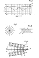
- FIG. 1 shows the dependence of the remanent band flux on the wavelength reproduced in the cited article for an oxidic (---- 1) and a metallic (-2) storage layer.
- the hysteresis loop of the force flow of both layers was assumed to be the same.
- the layer thickness of the metal strip (d M ) is therefore only about 1 of the thickness of the oxide strip (d 0 ).
- An isotropic magnetic layer is magnetized longitudinally at long wavelengths ( ⁇ ) at which ⁇ > d (d - layer thickness), since this state is the more energetically favorable because of the demagnetizing field.
- ⁇ the wavelength at which ⁇ > d (d - layer thickness)
- d the wavelength at which ⁇ > d (d - layer thickness)
- the ratio d: ⁇ increases and, because of the shear of the hysteresis loop, the remanent magnetization decreases.
- the direction perpendicular to the strip surface begins to have equal rights and becomes more energetically more favorable as the wavelength drops further, so that the magnetization is preferably in the normal direction.
- the retentive river 0 ⁇ now rises again.
- the wavelength is based on the layer thickness of a metal strip d M (about 0.3 ⁇ m).
- metal layers have a magnetic preferred axis in the direction of the surface normal of the recording material.
- the technology of metal layer production is only now emerging, while the technology of oxide layer production is generally highly perfected.
- the obvious idea of aligning the preferred axis of the magnetic pigments by means of a constant field, which acts on the still liquid pigment dispersion during the production process, is specified in DE-OS 31 48 769 for pigments with an aspect ratio of less than 3: 1.
- the limitation shows that the process still has significant shortcomings. Brings disadvantages in particular of the applied temperature drop to solidify the liquid dispersion, since Darun - ter the homogeneity of the coating suffers. It is equally unfavorable that the direct field directed perpendicular to the still liquid storage layer creates an extremely strong demagnetizing field against the direct field in the layer. This weakens the effective field and makes vertical orientation difficult.
- DE-OS 32 17 211 describes a further method for generating a magnetic anisotropy perpendicular to the layer surface.
- the magnetic pigment is subjected to heat treatment in the magnetic field.
- the powder can be exposed to this thermomagnetic treatment before or after it is applied in the same field to the substrate.
- This patent also has the defect that when the pigments are aligned in the same field, this is counteracted by a high demagnetizing field.
- the thermomagnetic treatment is carried out on the pigments located on the film, high demands must be placed on the thermal stability of the layer support. Another disadvantage is the high expenditure of time that is required for the thermomagnetic method.
- the invention is therefore the object of a method for producing a magnetic recording material with at least one layer of magnetic oxidic and / or metallic acicular pigments with shape anisotropy and / or another type of magnetic anisotropy z.
- the following structures should be realized with the method.
- the object is achieved according to the invention by a method for producing a magnetic recording material having at least one layer of magnetically anisotropic pigments which are dispersed in a binder, the magnetic dispersion being subjected to an external magnetic field in the liquid suspension state after application to the layer support, which acts essentially parallel to the layer normal, whereby the field orientation in the casting direction changes continuously by 180 0 while the field strength decreases, so that the pigments turn with their preferred axis into the normal axis of the layer and, due to the demagnetization or deletion effect, spatially small areas with form reduced stray field energy and the pigments are then fixed by drying.
- the demagnetization energy of the storage layer is thus significantly reduced.
- 3 shows such small areas with changing magnetization direction 11 and the partition walls 17.
- the drying point is placed at the point at which the wet layer enters the magnet arrangement, so that a spatially isotropic distribution of the preferred axes of the particles is achieved, that only a part of the preferred axes is more or less screwed into the layer normal.
- the drying point is placed at the point at which the wet layer leaves the magnet arrangement according to the invention.
- the drying and fixing point lies far away from the alignment arrangement.
- the wet layer passes through the arrangement according to the invention for aligning the particles in the normal direction of the layer.
- the particles then fall over like the micro sticks and are statistically distributed parallel to the layer surface.
- the method is not restricted to any specific magnetic material of the pigments. It applies, for example, to all magnetic pigments known today, such as Fe 3 0 4 , r-Fe 2 0 3 , Berthollide, Cr0 2 , metal powder, barium ferrite, rare earth magnet.
- the magnetic layer is composed of binders, solvents and other additives such as dispersants, lubricants, wetting agents.
- binders such as polyvinyl compounds, polyesters, polyurethanes, cellulose derivatives and the like are used as binders.
- flexible and rigid materials such as PET, polyolefins, cellulose derivatives, non-magnetic metals such as aluminum or ceramic materials such as glass are used as layer supports.
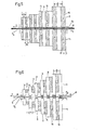
- FIG. 1 The arrangement consists of two identical chains of magnets (15), which are to be referred to as magnetic carpets (3, 4). These magnetic carpets lie symmetrically to the film (5) with the still liquid layer (6) on it. With arrow (7) is the movement marked in the direction of the film.
- the north (N) and south poles (S) of the carpets (3, 4) always face each other, so that perpendicular to the film (5) and layer (6), i.e. the line of symmetry, magnetic fields (8) are created, which are their direction change alternately.
- the strength of the fields decreases on the line of symmetry, in the direction (7) in which the still liquid layer moves through the magnet arrangement.
- the field (8) used for alignment and demagnetization decreases monotonously as possible.
- One way to do this is to consider manufacturing accuracy as a design focus.
- the many required individual parts of the many individual circles are manufactured in the same dimensions and magnetic values.
- the decrease in the field on the line of symmetry is then achieved by allowing the two identical magnetic circuit arrangements to wedge apart, as shown in FIG. 4.
- a low longitudinal component is required, which can be achieved by slightly shifting the two magnetic carpets (3, 4) in the running direction (7) or by guiding the layer carrier slightly outside the line of symmetry between the two pole chains.
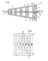
- FIGS. 5-7 Another possibility is to focus on an optimal field geometry of the entire straightening and demagnetization path. Examples of this are given in FIGS. 5-7.
- One of the principles of forming an optimal field geometry is that the field strength H E is designed to be as high as possible at the entrance of the layer (6) into the magnetic carpet arrangement (3, 4).
- the distance ⁇ E of the two magnetic carpets (3, 4) is always chosen to be as small as possible at the entrance.
- the mechanical guidance and the paint behavior limit the distance downwards.
- the pole width can be chosen somewhat larger at the entrance in favor of increasing the field strength (FIGS. 5, 7).
- the distance between the poles of a chain ( ) should be dimensioned as small as possible (FIGS. 5, 7), so that magnetic areas that are as spatially small as possible are formed in the layer.
- the stray field of the overall arrangement of the magnetic carpets (3, 4) does not interfere with the monotonously periodic decrease in the erase field upon exiting the layer (6) (g Fi. 5, 6, 7, 10), that is, the Starting point of the field lines of the total stray field of the arrangement is distributed over the entire length of the magnetic carpets (3, 4).
- the distance (a) between the two magnetic carpets (3, 4) should be as small and constant as possible from start to finish (1 - 3 mm).
- the magnetic energy provided by the magnets should decrease from the beginning to the end, i. H. the magnet volume should always get smaller.
- the magnetic circuits can be built up from bar and / or block magnets.
- the highly coercive magnetic materials with a high energy product such as barium ferrite and rare earth magnets, are preferred.
- the barium ferrite block magnets (16) (Fig. are often magnetized along the short form axis (arrows 18) and combined with soft magnetic material (9) with high saturation magnetization.
- Fig. 6 shows an example in which the decrease in the field (8) is achieved by shortening the contact surface between the hard and soft magnetic material.
- the dimensions b and - / L / 2 can also be reduced in the running direction of the storage layer.
- FIG. 7 shows a sketch.
- the bar magnets 15 made of CoSm have the magnetic preferred axis 18 perpendicular to the layer 6. Their volume (depth and length) decreases in the direction of the arrow (7).
- a soft magnetic flux conductor (9) serves to reduce the demagnetization factor of the individual magnetic circuits.
- Non-magnetic filling material (10) is attached between the magnets 15.
- electromagnetic systems they must usually be externally ventilated with a high level of technical effort in order to avoid explosions.
- the design and manufacture of the electromagnetic systems are based on that of electric motors, especially linear motors.
- electric motors especially linear motors.
- One method to change the current in the individual grooves and thus the field can be that between the teeth of the combs, electrical resistors are connected in parallel to the turns.
- the number of current-carrying wires (12) can also be changed, as shown in FIG. 8.
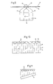
- the uprighting of the particles or the approximation to the vertical position of the particles can be achieved (FIG. 9) by directly covering the film (5) covered with the liquid layer 6 via a 0.1 to 1 mm wide gap (13) like netic circle 14 of permanent magnets 16 and soft magnetic flux conductor parts 9 leads. From the indicated course of the magnetic field (8) it can be seen that the layer (6) in the outlet is essentially subjected to a magnetic field perpendicular to the tape surface.
- an air flow adjustable in temperature and wind speed is blown against the direction of travel to solidify the dispersion on the substrate.
- the air flow can also be diverted perpendicular to the direction of flow in the middle third of an alternating field magnet arrangement, so that the pigments are still highly mobile in the first third, and the layer is intensified in the last third.
- the air flow can also be blown parallel to the layer plane, but perpendicular to the direction of travel. The person skilled in the art can test which method is the cheapest for each individual case.
- a modern means is the use of Peltier elements, with which different points of the magnet arrangement can be heated or cooled.
- UV radiation ultraviolet radiation, infrared radiation
- the film through the magnet arrangement can be done by rolling or baffles.
- the principle of levitation can also be used.
- the external demagnetization factor can usually be set to zero by means of a suitable sample shape, since the layer extension is greater than the layer thickness.
- the measurement in the normal direction is very difficult.
- the measuring field must magnetize the sample perpendicular to the layer surface, so that a very large demagnetizing field is created.
- the demagnetization factor is 1 or 4 ⁇ depending on the measurement system. Due to the high demagnetizing field, very high fields (greater than 10,000 ( can be used for magnetizing. Due to this fact, a vibration magnetometer in combination with a Weiss magneton has proven itself well.
- the alignment can be determined using X-ray images.
- the advantage of volume detection is here.
- test samples with longitudinal pigment particles can be produced by a suitable magnet system during the casting process. This technique is well known.
- Type (Fig. 10) magnetic carpet system made of the same individual parts.
- the two magnetic carpets (3, 4) consist of the same magnetic circuits strung together.
- the fields acting on the layer are removed by tilting the magnetic carpets (3, 4).
- the individual magnetic circles consist of block-shaped barium ferrite magnets 16 measuring 3 x 21 x 50 mm, which are magnetized over the shortest edge. Such magnets provide z.
- B. the stainless steel works Dortmund under the material designation 300 K. Rectangular rails made of soft magnetic conductive material 9 with the dimensions 3 x 25 x 200 flank the Barrium ferrite stones, which are arranged in the brick wall composite.
- the free space 10 is filled with non-magnetic filling material. A sequence of 50 north and south poles (N, S) was used.
- the entrance opening between the magnets is 1.5 mm to 2.0 mm.
- the opening angle can be changed to optimize the manufacturing conditions.
- the outlet opening can therefore be set between 1.5 mm and 18 mm.
- the maximum field strength at the entrance to the arrangement was 1,000-1,100 Oe.
- FIG. 11 2nd type (Fig. 11) with dissimilar CoSm magnets and soft magnetic backing.
- This type of magnetic carpet is shown in principle in FIG. 5.
- the non-magnetic material between the "bar magnets” (15) could be dispensed with, since CoSm has a sufficiently strong anisotropy.
- These bar magnets about 3 mm wide, were placed on a soft magnetic flux conductor 9, 5 mm thick, in order to depress the demagnetization factor of the circles.
- the bar magnets initially had a length of 10 mm, which dropped to zero over a length of about 30 cm.
- the magnetic usable surfaces were spaced about 2 - 3 mm apart. But they could also be tilted against each other.
- the additional magnets placed in front of the magnetic carpets (3, 4) have the task of facilitating the vertical position.
- the pigment particles are aligned longitudinally with two strips, whose poles of the same name face each other.
- the maximum field in the tape running direction was 1 100 Oe.
- the split strips, which are used to prepare the vertical position, are in principle shown in Fig. 9.
- the block-shaped permanent magnet 16 had a cross section of 3 x 23 mm and was made of barium ferrite (300 K).
- the soft magnetic yoke 9 had an overall height of 23 mm and an overall width of 10 mm.
- the gaps between the two magnets in series were 0.4 and 0.8 mm.
Abstract
Die Erindung betrifft ein Verfahren zur Herstellung eines magnetishen Aufzeichnungsmaterials mit mindestens einer Schicht aus magnetischen oxidischen und/oder metallischen nadelförmigen Pigmenten mit Formanisotropie und/oder einer anderen Art der magnetischen Anisotropie z.B. Kristall-, Spannungsanisotropie, magnetfeldinduzierte Anisotropie anzugeben, mit dem eine Schicht mit Senkrechtanisotropie oder über eine anfängliche Senkrechtanisotropie eine Schicht mit isotroper Verteilung der magnetischen Vorzugsachsen der Pigmente herstellbar ist. Nach dem erfindungsgemässen Verfahren wird die magnetische Dispersion nach dem Auftragen auf den Schichtträger im flüssigen Suspensionszustand einem äußeren magnetischen Feld unterworfen wird. Dabei fügen sich die Pigmente mit Ihrer Vorzugsachse in die Normalenachse der Schicht ein und werden anschließend durch Trocknen fixiert.The invention relates to a method for producing a magnetic recording material with at least one layer of magnetic oxide and / or metallic acicular pigments with shape anisotropy and / or another type of magnetic anisotropy e.g. Specify crystal, voltage anisotropy, magnetic field-induced anisotropy with which a layer with perpendicular anisotropy or, via an initial vertical anisotropy, a layer with an isotropic distribution of the magnetic preferred axes of the pigments can be produced. According to the method according to the invention, the magnetic dispersion is subjected to an external magnetic field in the liquid suspension state after application to the layer support. The preferred axis of the pigments fits into the normal axis of the layer and is then fixed by drying.
Description
Die Erfindung betrifft ein Verfahren zur Herstellung eines magnetischen Aufzeichnungsmaterials mit mindestens einer Schicht, bestehend aus in Bindemittel eingebetteten magnetischen Pigmenten, wobei das Aufzeichnungsmaterial eine magnetische Vorzugsachse senkrecht zur Schichtoberfläche oder eine verfahrensmäßig daraus abgeleitete Schichtstruktur besitzen.The invention relates to a method for producing a magnetic recording material with at least one layer consisting of magnetic pigments embedded in binder, the recording material having a magnetic preferred axis perpendicular to the layer surface or a layer structure derived therefrom in terms of process.
Die ersten magnetischen Aufzeichnungsmaterialien von technischer Bedeutung, die aus Bindemittel mit eingebetteten magnetischen Pigmenten bekannt wurden, waren magnetisch isotrope Schichten. Es wurden kubische Eisenoxidteilchen, die in einem Bindemittel dispergiert waren, mit einem Gießer auf eine Unterlage aufgetragen. Die Gießeinrichtung enthielt keine magnetischen Elemente.The first magnetic recording materials of technical importance, which were known from binders with embedded magnetic pigments, were magnetically isotropic layers. Cubic iron oxide particles dispersed in a binder were applied to a base with a caster. The casting device contained no magnetic elements.
Um die Speicherdichte zu erhöhen, benutzt man seit den fünfziger Jahren längliche Pigmentteilchen, die während des Gießvorganges durch ein Magnetfeld ausgerichtet werden. Es entsteht eine magnetische Speicherschicht mit einer Vorzugsachse in Bandlaufrichtung. Diese Schichten bewährten sich 2 bis 3 Jahrzehnte, da die aufgezeichneten halben Wellenlängen stets größer als die Schichtdicken waren.In order to increase the storage density, elongated pigment particles have been used since the 1950s, which are aligned by a magnetic field during the casting process. A magnetic storage layer is created with a preferred axis in the tape running direction. These layers proved their worth for 2 to 3 decades, since the half wavelengths recorded were always greater than the layer thicknesses.
Mit der Notwendigkeit, magnetische Impulse und Signale im 1-µm-Bereich zu fixieren, wurden Aufzeichnungsmaterialien mit senkrecht zur Oberfläche stehender magnetischer Vorzugsachse interessant. So beschreibt DP 12 58 146 (08.12.64) bereits eine solche Schicht.With the need to fix magnetic impulses and signals in the 1 µm range, recording materials with a magnetic preferred axis perpendicular to the surface became interesting. DP 12 58 146 (08. 1 2.64) already describes such a layer.
Es ist auch bekannt aus "Internationale Elektronische Rundschau" 1970 Nr. 10, Seite 251 - 255, Bild 5 (siehe Fig. l), daß für kurze aufzuzeichnende Wellenlängen λ die senkrecht zur Schichtoberfläche stehende Vorzugsrichtung von Vorteil ist. Die Fig. 1 zeigt die im zitierten Artikel wiedergegebene Abhängigkeit des remanenten Bandflusses von der Wellenlänge 
![]()
![]()
Iwasaki hat in den letzten Jahren die Senkrechtaufzeichnung auf Metallschichten besonders auf CoCr-Schichten beschrieben, unter anderem in "Magnetmaterial für Senkrechtaufzeichnung"Iwasaki has described vertical recording on metal layers, particularly on CoCr layers, in recent years, inter alia in "Magnetic material for vertical recording"
Proceeding of 1982 Sendai Symposium on Perpendicular Magnetic Recording, März 11. - 12, Seite 1 - 30, Vortrag No. 15, Research Institute of Electrical Communication, Sendai, Japan und "An Analysis for the Magnetization Mode for High Density Magnetic Recording" (IEEE Transaction der Magnetics Vol. on MAG 13, No. 5, 1977, S. 1272 - 77).Proceeding of 1982 Sendai Symposium on Perpendicular Magnetic Recording, March 11th - 12th, Pages 1 - 30, Lecture No. 15, Research Institute of Electrical Communication, Sendai, Japan and "An Analysis for the Magnetization Mode for High Density Magnetic Recording" (IEEE Transaction der Magnetics Vol. On
Diese Metallschichten besitzen eine magnetische Vorzugsachse in Richtung der Oberflächennormalen des Aufzeichnungsmaterials. Die Technologie der Metallschichtherstellung ist heute jedoch erst im Entstehen begriffen, während die Technologie der Oxidschichtherstellung im allgemeinen hoch perfektioniert ist. Der naheliegende Gedanke, die Vorzugsachse der magnetischen Pigmente durch ein Gleichfeld, das während des Herstellungsvorganges auf die noch flüssige Pigmentdispersion wirkt, auszurichten, wird in DE-OS 31 48 769 für Pigmente mit einem Längen-/Breitenverhältnis von kleiner 3:1 angegeben. Die Einschränkung zeigt, daß das Verfahren noch erhebliche Mängel aufweist. Nachteile bringt insbesondere der angewandte Temperatursturz zur Verfestigung der flüssigen Dispersion, da darun- ter die Homogenität der Schicht leidet. Gleichermaßen ungünstig ist, daß durch das senkrecht zur noch flüssigen Speicherschitht gerichtete Gleichfeld ein extrem starkes entmagnetisierendes Feld entgegen dem Gleichfeld in der Schicht entsteht. Das wirksame Feld wird dadurch sehr geschwächt und die Senkrechtorientierung erschwert.These metal layers have a magnetic preferred axis in the direction of the surface normal of the recording material. The technology of metal layer production is only now emerging, while the technology of oxide layer production is generally highly perfected. The obvious idea of aligning the preferred axis of the magnetic pigments by means of a constant field, which acts on the still liquid pigment dispersion during the production process, is specified in DE-OS 31 48 769 for pigments with an aspect ratio of less than 3: 1. The limitation shows that the process still has significant shortcomings. Brings disadvantages in particular of the applied temperature drop to solidify the liquid dispersion, since Darun - ter the homogeneity of the coating suffers. It is equally unfavorable that the direct field directed perpendicular to the still liquid storage layer creates an extremely strong demagnetizing field against the direct field in the layer. This weakens the effective field and makes vertical orientation difficult.
In DE-OS 32 17 211 ist ein weiteres Verfahren zur Erzeugung einer magnetischen Anisotropie senkrecht zur Schichtoberfläche beschrieben. Zur Unterstützung der Senkrechtorientierung durch ein Gleichfeld wird hier das magnetische Pigment einer Wärmebehandlung im Magnetfeld unterworfen. Dabei kann das Pulver vor oder nach dem Aufbringen im Gleichfeld auf den Schichtträger dieser thermomagnetischen Behandlung ausgesetzt werden. Auch diesem Patent haftet der Mangel an, daß bei Ausrichtung der Pigmente im Gleichfeld diesem ein hohes entmagnetisierendes Feld entgegenwirkt. Hinzukommt, daß bei Durchführung der thermomagnetischen Behendlung bei-den-auf der Folie befindlichen Pigmente hohe Forderungen an die thermische Stabilität des Schichtträgers gestellt werden müssen. Nachteilig ist auch der hohe Zeitaufwand, der für das thermomagnetische Verfahren erforderlich ist.DE-OS 32 17 211 describes a further method for generating a magnetic anisotropy perpendicular to the layer surface. To support the vertical orientation by means of a constant field, the magnetic pigment is subjected to heat treatment in the magnetic field. The powder can be exposed to this thermomagnetic treatment before or after it is applied in the same field to the substrate. This patent also has the defect that when the pigments are aligned in the same field, this is counteracted by a high demagnetizing field. In addition, when the thermomagnetic treatment is carried out on the pigments located on the film, high demands must be placed on the thermal stability of the layer support. Another disadvantage is the high expenditure of time that is required for the thermomagnetic method.
Die Erfindung stellt sich aaher die Aufgabe, ein Verfahren zur Herstellung eines magnetischen Aufzeichnungsmaterials mit mindestens einer Schicht aus magnetischen oxidischen und/oder metallischen nadelförmigen Pigmenten mit Formanisotropie und/oder einer anderen Art der magnetischen Anisotropie z. B. Kristall-, Spannungsanisotropie, magnetfeldinduzierte Anisotropie anzugeben, mit dem eine Schicht mit Senkrechtanisotropie oder über eine anfängliche Senkrechtanisotropie eine Schicht mit isotroper Verteilung der magnetischen Vorzugsachsen der Pigmente herstellbar ist. Speziell sollen sich mit dem Verfahren die folgenden Strukturen realisieren lassen.The invention is therefore the object of a method for producing a magnetic recording material with at least one layer of magnetic oxidic and / or metallic acicular pigments with shape anisotropy and / or another type of magnetic anisotropy z. B. crystal, voltage anisotropy, magnetic field-induced anisotropy with which a layer with perpendicular anisotropy or an initial vertical anisotropy can be used to produce a layer with an isotropic distribution of the magnetic preferred axes of the pigments. In particular, the following structures should be realized with the method.
- 1. Schichten, bei denen die magnetische Vorzugsachse der Teilchen in Richtung der Schichtnormalen weist und bei deren Herstellung die oben genannten Mängel vermieden werden. 1st Layers in which the magnetic preferred axis of the particles points in the direction of the layer normals and in the manufacture of which the above-mentioned defects are avoided.
- 2. Herstellung räumlich isotroper Schichten aus Pigmenten mit magnetischer Vorzugsachse.2. Production of spatially isotropic layers from pigments with a preferred magnetic axis.
- 3. Herstellung von Schichten mit flächenhafter statistischer Verteilung der magnetischen Vorzugsachsen der Teilchen parallel zur Schichtebene.3. Production of layers with a flat statistical distribution of the magnetic preferred axes of the particles parallel to the layer plane.
- 4. Herstellung von Schichten mit flächenhafter statistischer Verteilung der magnetischen Vorzugsachsen der Teilchen, wobei die Verteilungsebene senkrecht zur Schichtebene und in Speicherspurrichtung liegt.4. Production of layers with areal statistical distribution of the magnetic preferred axes of the particles, the distribution plane being perpendicular to the layer plane and in the direction of the storage track.
Die Aufgabe-wird erfindungsgemäß gelöst durch ein Verfahren zur Herstellung eines magnetischen Aufzeichnungsmaterials mit mindestens einer Schicht aus magnetisch anisotropen Pigmenten, die in einem Bindemittel dispergiert sind, wobei die magnetische Dispersion nach dem Auftragen auf den Schichtträger im flüssigen Suspensionszustand einem äußeren magnetischen Feld unterworfen wird, das im wesentlichen parallel zur Schichtnormalen wirkt, wobei die Feldorientierung in Gießrichtung unter gleichzeitiger Abnahme der Feldstärke laufend um 1800 wechselt, so daß die Pigmente mit ihrer Vorzugsachse in die Normalenachse der Schicht eindrehen und sich durch den Entmagnetisierungs- bzw. Löscheffekt räumlich kleine Bereiche mit verringerter Streufeldenergie bilden und die Pigmente anschließend durch Trocknen fixiert werden.The object is achieved according to the invention by a method for producing a magnetic recording material having at least one layer of magnetically anisotropic pigments which are dispersed in a binder, the magnetic dispersion being subjected to an external magnetic field in the liquid suspension state after application to the layer support, which acts essentially parallel to the layer normal, whereby the field orientation in the casting direction changes continuously by 180 0 while the field strength decreases, so that the pigments turn with their preferred axis into the normal axis of the layer and, due to the demagnetization or deletion effect, spatially small areas with form reduced stray field energy and the pigments are then fixed by drying.
Die Entmagnetisierungsenergie der Speicherschicht ist damit wesentlich herabgesetzt. Fig. 3 zeigt derart kleine Bereiche mit wechselnder Magnetisierungsrichtung 11 und den Trennwänden 17.The demagnetization energy of the storage layer is thus significantly reduced. 3 shows such small areas with changing
Die verschiedenen Schichtstrukturen werden erfindungsgemäß durch Verlagerung des Trocknungspunktes der Schicht bezüglich der Richtfeldanordnung und erforderlichenfalls durch eine zusätzliche Feldkomponente in Aufzeichnungsrichtung erzielt. Es ergeben sich folgende Herstellungsverfahren:
- Bei der Herstellung von Schichten, bei denen die magnetische Vorzugsachse in Richtung der Schichtnormalen weisen soll, läßt man die Schicht in der erfindungsgemäßen Magnetfeldanordnung erstarren.
- When producing layers in which the preferred magnetic axis is to point in the direction of the layer normal, the layer is allowed to solidify in the magnetic field arrangement according to the invention.
Bei der Herstellung räumlich isotroper Schichten aus magnetischen Teilchen mit einer magnetischen Vorzugsachse gibt es zwei Möglichkeiten: Der Trocknungspunkt wird an die Stelle gelegt, an der die nasse Schicht in die Magnetanordnung einläuft, so daß eine räumlich isotrope Verteilung der Vorzugsachsen der Teilchen dadurch erreicht wird, daß nur ein Teil der Vorzugsachsen mehr oder weniger in die Schichtnormale eingedreht wird. Der Trocknungspunkt wird an die Stelle gelegt, an der die nasse Schicht die erfindungsgemäße Magnetanordnung verläßt. Die Teilchen, die in der Magnetanordnung senkrecht gestellt wurden, fallen auseinander und werden im Moment des Fallens mit mehr oder weniger großen Abweichungen von der Normalen fixiert.There are two options for producing spatially isotropic layers from magnetic particles with a magnetic preferred axis: the drying point is placed at the point at which the wet layer enters the magnet arrangement, so that a spatially isotropic distribution of the preferred axes of the particles is achieved, that only a part of the preferred axes is more or less screwed into the layer normal. The drying point is placed at the point at which the wet layer leaves the magnet arrangement according to the invention. The particles, which were placed vertically in the magnet arrangement, fall apart and are fixed with more or less large deviations from the normal at the moment of falling.
Bei der Herstellung von Schichten mit flächenhafter statistischer Verteilung der magnetischen Vorzugsachsen parallel zur Schichtebene liegt der Trocknungs- und Fixierungspunkt weit weg von der Richtanordnung. Die nasse Schicht passiert die erfindungsgemäße Anordnung zur Ausrichtung der Teilchen in Normalenrichtung der Schicht. Die Teilchen fallen dann wie die Mikadostäbchen um und liegen parallel zur Schichtoberfläche statistisch verteilt.In the production of layers with an areal statistical distribution of the magnetic preferred axes parallel to the layer plane, the drying and fixing point lies far away from the alignment arrangement. The wet layer passes through the arrangement according to the invention for aligning the particles in the normal direction of the layer. The particles then fall over like the micro sticks and are statistically distributed parallel to the layer surface.
Die Fig. 2 zeigt die sternförmige flächenhafte statistische Verteilung der magnetischen Vorzugsachsen der Teilchen der Schicht.2 shows the star-shaped areal statistical distribution of the magnetic preferred axes of the particles of the layer.
Bei der Herstellung von Schichten mit flächenhafter Verteilung der magnetischen Vorzugsachsen, bei der die Verteilungsebene senkrecht zur Schichtebene und in Speicherspurrichtung liegt, erfolgt die Trocknung in einer erfindungsgemäßen Magnetfeldanordnung, die aber zusätzlich eine Feldkomponente in Bandlaufrichtung besitzt, deren Betrag 1/4 des Betrages der Senkrechtkomponente nicht übersteigt.In the production of layers with areal distribution of the magnetic preferred axes, in which the distribution plane is perpendicular to the layer plane and in the direction of the storage track, drying takes place in a magnetic field arrangement according to the invention, but which additionally has a field component in the direction of tape travel, the amount of which is 1/4 the amount of the vertical component does not exceed.
Erfindungsgemäß ist das Verfahren auf kein bestimmtes magnetisches Material der Pigmente beschränkt. Es gilt beispielsweise für alle heute bekannten Magnetpigmente, wie Fe304, r-Fe 203, Berthollide, Cr02, Metallpulver, Bariumferrite,Selten- erdmagnet.According to the invention, the method is not restricted to any specific magnetic material of the pigments. It applies, for example, to all magnetic pigments known today, such as Fe 3 0 4 , r-Fe 2 0 3 , Berthollide, Cr0 2 , metal powder, barium ferrite, rare earth magnet.
Die magnetische Schicht ist neben den ferromagnetischen Pigmenten aus Bindemitteln, Lösungsmittel und sonstigen Zusätzen wie Dispergatoren, Gleitmitteln, Netzmitteln zusammengesetzt. Als Bindemittel werden die üblicherweise verwendeten hochmolekularen Harze wie Polyvinylverbindungen, Polyester, Polyurethane, Cellulosederivate u. ä. eingesetzt. Als Schichtträger werden flexible und starre Materialien wie PET, Polyolefine, Cellulosederivate, nichtmagnetische Metalle wie Aluminium oder keramische Materialien wie Glas verwendet.In addition to the ferromagnetic pigments, the magnetic layer is composed of binders, solvents and other additives such as dispersants, lubricants, wetting agents. The commonly used high molecular weight resins such as polyvinyl compounds, polyesters, polyurethanes, cellulose derivatives and the like are used as binders. Ä. used. Flexible and rigid materials such as PET, polyolefins, cellulose derivatives, non-magnetic metals such as aluminum or ceramic materials such as glass are used as layer supports.
Zur Erfindung gehört auch die Kombination der nach diesem Verfahren herstellbaren Schichttypen, wie auf S. 5 beschrieben, untereinander und mit anderen Schichttypen, mit anderem Koerzitivfeld und/oder anderer Anisotropieart. Hierbei sind zwei Gruppen zu unterscheiden:
- Mehrfachschichten zur besseren Nutzung von Aufzeichnungs-und Abtastorganen und Mehrfachschichten, bei denen jede Schicht Träger einer anderen Information ist, z. B. Sprache und Musik.
- Multi-layers for better use of recording and scanning devices and multi-layers, in which each layer is a carrier of different information, e.g. B. Language and music.
Von besonderer Bedeutung sind Mehrfachschichten, die das Spaltfeld eines Ringkopfes nachbilden. Als Oberschicht, die direkt am Kopfspiegel anliegt, wird stets eine erfindungsgemäße Schicht mit einer Vorzugsachse in Normalenrichtung zur Schichtebene verwendet. Als Unterschicht dienen
- a) Schichten mit einer magnetischen Vorzugsachse in Bandlaufrichtung. Das können gerichtete Pigmertschichten, z. B. α-Fe2O3, Fe304, CrO2, Metallpulver, homogene Metallschichten sein. Das Koerzitivfeld Heu liegt zwischen dem der Senkrechtschicht HCS und einem 1/4 davon.
- b) Weichmagnetische isotrope Schichten mit niederem Koerzitivfeldern, die den magnetischen Fluß der Aufzeichnung schließen. Es sind auch hier Pigment- und Metallschichten möglich.
- a) Layers with a magnetic preferred axis in the tape running direction. This can be directed pigment layers, e.g. B. α-Fe 2 O 3 , Fe304, CrO 2 , metal powder, homogeneous metal layers. The coercive field H eu lies between that of the vertical layer H CS and a 1/4 thereof.
- b) Soft magnetic isotropic layers with low coercive fields, which close the magnetic flux of the recording. Here too, pigment and metal layers are possible.
Es gibt verschiedene Methoden, in einer Achse senkrecht zur Speicherschicht ein erfindungsgemäßes Magnetfeld während des Herstellungsprozesses wirken zu lassen. Einige werden hier beispielhaft aufgeführt:There are various methods of allowing an inventive magnetic field to act in an axis perpendicular to the storage layer during the manufacturing process. Some are listed here as examples:
Anordnungen aus Permanentmagneten besitzen den Vorteil, daß bei der Herstellung des Aufzeichnungsmaterials die aufwendigen Maßnahmen zur Verhinderung von Explosionen des Lösemittelgemisches des Gießlackes entfallen. In Figur 4 ist das Prinzip einer solchen Anordnung dargestellt. Die Anordnung besteht aus zwei gleichen Ketten von Magneten (15), die als Magnetteppiche (3, 4) bezeichnet werden sollen. Diese Magnetteppiche liegen symmetrisch zur Folie (5) mit der noch flüssigen Schicht (6)darauf. Mit Pfeil (7) ist die Bewegungsrichtung der Folie markiert. Die Nord- (N) und Südpole (S) der Teppiche (3, 4) stehen sich stets gegenüber, so daß senkrecht zur Folie (5) und Schicht (6), also der Symmetrielinie, Magnetfelder (8) entstehen, die ihre Richtung alternierend ändern. Die Stärke der Felder nimmt auf der Symmetrielinie, in der Richtung (7), in der sich die noch flüssige Schicht durch die Magnetanordnung bewegt, ab. Bei dem Aufbau der Magnetteppiche ist zu beachten, daß das zur Ausrichtung und Entmagnetisierung dienende Feld (8) möglichst gleichmäßig monoton abnimmt. Eine Möglichkeit dies zu realisieren, besteht darin, die Fertigungsgenauigkeit als konstruktiven Schwerpunkt anzusehen. .Die vielen erforderlichen Einzelteile der vielen Einzelkreise werden in Maßen und magnetischen Werten gleich gefertigt. Die Abnahme des Feldes auf der Symmetrielinie erreicht man dann dadurch, daß man die beiden gleichen Magnetkreisanordnungen keilförmig auseinandergehen läßt, wie es Fig. 4 darstellt. In speziellen Fällen wird eine geringe Längskomponente gewünscht, die man erreicht durch eine leichte Verschiebung der zwei Magnetteppiche (3, 4) in Laufrichtung (7) oder durch eine Führung des Schichtträgers leich außerhalb der Symmetrielinie zwischen den beiden Polketten. Eine andere Möglichkeit besteht darin, den Schwerpunkt auf eine optimale Feldgeometrie der gesamten Richt- und Entmagnetisierungsstrecke zu legen. In den Figuren 5 - 7 sind Beispiele hierfür angegeben. Zu den Prinzipien der Ausbildung einer optimalen Feldgeometrie gehört, daß am Eingang der Schicht (6) in die Magnetteppichanordnung (3,4) die Feldstärke HE möglichst hoch ausgelegt wird. Der Abstand αE der beiden Magnetteppiche (3, 4) wird am Eingang stets möglichst klein gewählt. Die mechanische Führung und das Lackverhalten begrenzen den Abstand nach unten. Die Polbreite kann am Eingang zugunsten einer Feldstärkenerhöhung etwas größer gewählt werden (Figuren 5, 7).Arrangements made of permanent magnets have the advantage that the elaborate measures to prevent explosions of the solvent mixture of the casting lacquer are omitted in the production of the recording material. The principle of such an arrangement is shown in FIG. The arrangement consists of two identical chains of magnets (15), which are to be referred to as magnetic carpets (3, 4). These magnetic carpets lie symmetrically to the film (5) with the still liquid layer (6) on it. With arrow (7) is the movement marked in the direction of the film. The north (N) and south poles (S) of the carpets (3, 4) always face each other, so that perpendicular to the film (5) and layer (6), i.e. the line of symmetry, magnetic fields (8) are created, which are their direction change alternately. The strength of the fields decreases on the line of symmetry, in the direction (7) in which the still liquid layer moves through the magnet arrangement. When setting up the magnetic carpets, it should be noted that the field (8) used for alignment and demagnetization decreases monotonously as possible. One way to do this is to consider manufacturing accuracy as a design focus. The many required individual parts of the many individual circles are manufactured in the same dimensions and magnetic values. The decrease in the field on the line of symmetry is then achieved by allowing the two identical magnetic circuit arrangements to wedge apart, as shown in FIG. 4. In special cases, a low longitudinal component is required, which can be achieved by slightly shifting the two magnetic carpets (3, 4) in the running direction (7) or by guiding the layer carrier slightly outside the line of symmetry between the two pole chains. Another possibility is to focus on an optimal field geometry of the entire straightening and demagnetization path. Examples of this are given in FIGS. 5-7. One of the principles of forming an optimal field geometry is that the field strength H E is designed to be as high as possible at the entrance of the layer (6) into the magnetic carpet arrangement (3, 4). The distance α E of the two magnetic carpets (3, 4) is always chosen to be as small as possible at the entrance. The mechanical guidance and the paint behavior limit the distance downwards. The pole width can be chosen somewhat larger at the entrance in favor of increasing the field strength (FIGS. 5, 7).
Umgekehrt liegen die Verhältnisse am Ausgang der Schicht aus der Magnetanordnung (3, 4). Hier sollte der Abstand der Pole einer Kette (![]()
![]()
Zur optimalen Feldgeometrie gehört auch, daß das Streufeld der Gesamtanordnung der Magnetteppiche (3, 4) beim Verlassen der Schicht (6) nicht die monoton periodische Abnahme des Löschfeldes stört (Fig. 5, 6, 7, 10), d. h., daß der Ansatzpunkt der Feldlinien des Gesamtstreufeldes der Anordnung auf die gesamte Länge der Magnetteppiche (3, 4) verteilt wird.For optimum field geometry also means that the stray field of the overall arrangement of the magnetic carpets (3, 4) does not interfere with the monotonously periodic decrease in the erase field upon exiting the layer (6) (g Fi. 5, 6, 7, 10), that is, the Starting point of the field lines of the total stray field of the arrangement is distributed over the entire length of the magnetic carpets (3, 4).
Die Überlegungen über die optimale Feldgeometrie wird dahingehend zusammengefaßt, daß der Abstand (a) zwischen den bei- den Magnetteppichen (3, 4) möglichst von Anfang bis Ende klein und gleichbleibend sein sollte (1 - 3 mm). Die von den Magneten zur Verfügung gestellte magnetische Energie sollte vom Anfang zum Ende hin abnehmen, d. h. das Magnetvolumen sollte immer kleiner werden.The considerations regarding the optimal field geometry are summarized in such a way that the distance (a) between the two magnetic carpets (3, 4) should be as small and constant as possible from start to finish (1 - 3 mm). The magnetic energy provided by the magnets should decrease from the beginning to the end, i. H. the magnet volume should always get smaller.
Der Aufbau der Magnetkreise kann aus Stab- und/oder Blockmagneten erfolgen. Bevorzugt werden die hochkoerzitiven Magnetmaterialien mit hohem Energieprodukt, wie Bariumferrit- und Seltenerdmagnete. Die Blockmagnete (16) aus Bariumferrit (Fig. werden häufig über die kurze Formachse magnetisiert (Pfeile 18) und kombiniert mit weichmagnetischem Material (9) mit hoher Sättigungsmagnetisierung eingesetzt. Fig. 6 zeigt ein Beispiel, in dem die Abnahme des Feldes (8) durch Verkürzung der Anlagefläche zwischen hart- und weichmagnetischem Material erreicht wird. Bei ähnlichem Aufbau können auch noch die Maße b und-/L/2 in Laufrichtung der Speicherschicht verringert werden.The magnetic circuits can be built up from bar and / or block magnets. The highly coercive magnetic materials with a high energy product, such as barium ferrite and rare earth magnets, are preferred. The barium ferrite block magnets (16) (Fig. are often magnetized along the short form axis (arrows 18) and combined with soft magnetic material (9) with high saturation magnetization. Fig. 6 shows an example in which the decrease in the field (8) is achieved by shortening the contact surface between the hard and soft magnetic material. With a similar structure, the dimensions b and - / L / 2 can also be reduced in the running direction of the storage layer.
Magnetteppiche mit Seltenerdmagneten wird man wegen des erhöhten Energieproduktes dieses Materials anders konstruieren. Die Figur 7 zeigt eine Skizze. Die Stabmagnete 15 aus CoSm weisen mit der magnetischen Vorzugsachse 18 senkrecht zur Schicht 6. Ihr Volumen (Tiefe und Länge) nimmt in Pfeilrichtung (7) ab. Auf der Rückseite dient ein weichmagnetischer Flußleiter (9) der Verringerung des Entmagnetisierungsfaktors der einzelnen Magnetkreise. Zwischen den Magneten 15 ist unmagnetisches Füllmaterial (10) angebracht.Magnetic carpets with rare earth magnets will be constructed differently due to the increased energy product of this material. Figure 7 shows a sketch. The
Wendet man Elektromagnetsysteme an, so müssen diese beim Gießvorgang zur Vermeidung von Explosionen meist mit hohem technischen Aufwand fremd belüftet werden. Andererseits bieten sie den Vorteil, daß sich die Felder durch Stromänderung leicht verändern lassen und damit den jeweiligen Pigment- und Dispersionsbedingungen angepaßt werden können.If electromagnetic systems are used, they must usually be externally ventilated with a high level of technical effort in order to avoid explosions. On the other hand, they offer the advantage that the fields can be easily changed by changing the current and can thus be adapted to the respective pigment and dispersion conditions.
Konstruktion und Fertigung der Elektromagnetsysteme lehnen sich an die von Elektromotoren, besonders Linearmotoren, an. Im Prinzip handelt es sich wieder um zwei Ketten von Magnetkreisen, wie bei den Permanentmagnetsystemen. Dies führt zu zwei Kämmen aus weichmagnetischem Material 10 (Fig. 8), in deren Nuten die stromführenden Drähte (12) eingelegt sind. Eine Methode, um den Strom in den einzelnen Nuten und damit das wirkende Feld verändern zu können, besteht darin, daß zwischen den Zinken der Kämme elektrische Widerstände paralfel zu den Windungen geschaltet werden. Auch die Zahl der stromführenden Drähte (12) kann, wie in Fig. 8 gezeigt, verändert werden.The design and manufacture of the electromagnetic systems are based on that of electric motors, especially linear motors. In principle, there are again two chains of magnetic circuits, as in the permanent magnet systems. This leads to two combs made of soft magnetic material 10 (FIG. 8), in the grooves of which the current-carrying wires (12) are inserted. One method to change the current in the individual grooves and thus the field can be that between the teeth of the combs, electrical resistors are connected in parallel to the turns. The number of current-carrying wires (12) can also be changed, as shown in FIG. 8.
Es wurden Anordnungen beschrieben, bei denen die Ausrichtung der Teilchen durch ein senkrecht zur Bandoberfläche stehendes in der Richtung wechselndes und abnehmendes Feld erreicht wird.Arrangements have been described in which the alignment of the particles is achieved by a field which changes and decreases in the direction perpendicular to the band surface.
Zur Erfindung gehört außerdem, daß die Senkrechtstellung der Teilchen durch Zusatzanordnungen vorbereitet wird, um bessere Ergebnisse zu erzielen. Diese Zusatzeinrichtungen bewirken:
- Eine Ausrichtung der Teilchen in Bandlaufrichtung vor dem Eintritt der Teilchen in die bisher beschriebene Magnetanordnung,
- eine Annäherung an die Senkrechtstellung vor dem Eintritt der Teilchen in die bisher beschriebene Magnetanordnung.
- Sie können einzeln oder in Kombination den Magnetteppichanordnungen (3, 4) vorangestellt werden.
- Die Ausrichtung von Teilchen in Bandlaufrichtung ist Stand der Technik und wird daher hier nicht im einzelnen äusgeführt. Häufig wird das Magnetfeld zweier sich gegenüberstehender gleichnamiger Pole benutzt. Die Folie wird auf der Symmetrielinie zwischen den Polen durchgeführt.
- Alignment of the particles in the direction of tape travel before the particles enter the previously described magnet arrangement,
- an approximation of the vertical position prior to entry of the particles in the manner described previously Ma g netanordnung.
- They can precede the magnetic carpet arrangements (3, 4) individually or in combination.
- The alignment of particles in the direction of belt travel is state of the art and is therefore not described in detail here. The magnetic field of two opposite poles of the same name is often used. The foil is carried out on the line of symmetry between the poles.
Das Aufrichten der Teilchen bzw. die Annäherung an die Senkrechtstellung der Teilchen erreicht man dadurch (Fig. 9), daß man die mit der flüssigen Schicht 6 bedeckte Folie (5) direkt über einen 0,1 bis 1 mm breiten Spalt (13) eines magnetischen Kreises 14 aus Permanentmagneten 16 und weichmagnetischen Flußleiterteilen 9 führt. Aus dem angedeuteten Verlauf des Magnetfeldes (8) ersieht man, daß die Schicht (6) im Auslauf im wesentlichen einem senkrecht zur Bandoberfläche stehenden Magnetfeld unterworfen ist.The uprighting of the particles or the approximation to the vertical position of the particles can be achieved (FIG. 9) by directly covering the film (5) covered with the
Bei der Herstellung der Schichten nach dem erfindungsgemäßen Verfahren werden an die Trocknung erhöhte Genauigkeitsanforderungen gestellt. Es sind jedoch grundsätzlich keine andersartigen Kontrollsensoren oder Konstruktionsprinzipien wie bei der konventionellen Bandherstellung anzuwenden. Eine Trocknung der nassen Magnetschicht in gegenströmender Luft mit genauer Temperaturüberwachung ist eine erprobte Möglichkeit. Eine genauere Einhaltung der geforderten Temperaturen bzw. Trocknungsbedingungen läßt sich erfindungsgemäß durch mehrere quer zur Folienlaufrichtung aufeinanderfolgende, verschiedenartige und geregelte Luftströme erreichen.When the layers are produced by the method according to the invention, increased accuracy requirements are placed on the drying. In principle, however, there are no other control sensors or design principles to be used as in conventional strip production. Drying the wet magnetic layer in countercurrent air with precise temperature monitoring is a tried and tested option. A more precise maintenance of the required temperatures or drying conditions can be achieved according to the invention by several different and controlled air flows which are successive and transverse to the film running direction.
In einem Fall wird zur Verfestigung der Dispersion auf dem Schichtträger ein in Temperatur und Windgeschwindigkeit einstellbarer Luftstrom gegen die Laufrichtung.geblasen. Der Luftstrom kann auch im mittleren Drittel einer Wechselfeldmagnetanordnung senkrecht zur Strömungsrichtung abgeleitet werden, so daß im ersten Drittel eine noch hohe Beweglichkeit der Pigmente gegeben ist, und im letzten Drittel eine verstärkte Verfestigung der Schicht erfolgt. Auch kann der Luftstrom parallel zur Schichtebene, jedoch senkrecht zur Laufrichtung geblasen werden. Welche Methode für den Einzelfall am günstigsten ist, kann durch den Fachmann von Fall zu Fall erprobt werden.In one case, an air flow adjustable in temperature and wind speed is blown against the direction of travel to solidify the dispersion on the substrate. The air flow can also be diverted perpendicular to the direction of flow in the middle third of an alternating field magnet arrangement, so that the pigments are still highly mobile in the first third, and the layer is intensified in the last third. The air flow can also be blown parallel to the layer plane, but perpendicular to the direction of travel. The person skilled in the art can test which method is the cheapest for each individual case.
. Bewährt hat sich auch die Magnetanordnung durch Flüssigkeiten wie Wasser an den entsprechenden Stellen zu erhitzen oder zu kühlen, damit sich die geforderten Trocknungsstellen ergeben.. It has also proven useful to heat or cool the magnet arrangement with liquids such as water at the appropriate points, so that the required drying points result.
Ein modernes Mittel ist der Einsatz von Peltierelementen, mit denen verschiedene Stellen der Magnetanordnung erwärmt oder abgekühlt werden können.A modern means is the use of Peltier elements, with which different points of the magnet arrangement can be heated or cooled.
Der Einsatz von Strahlung zur Trocknung (UV-Strahlung, Ultrarot-Strahlung) ist bekannt.The use of radiation for drying (UV radiation, infrared radiation) is known.
Die Folienführung durch die Magnetanordnung kann durch Walzen oder Leitbleche erfolgen. Auch das Prinzip der Schwebeführung ist einsetzbar.The film through the magnet arrangement can be done by rolling or baffles. The principle of levitation can also be used.
Es wird nun auf die Bewertung des Grades der Senkrechtstellung eingegangen werden. Hierzu gibt es verschiedene Möglichkeiten.The evaluation of the degree of vertical position will now be discussed. There are various ways of doing this.
Um die Lage der Teilchen in einer Magnetschicht zu bestimmen, werden die Hystereseschleifen der Schicht in den drei Raumrichtungen gemessen:
- In Bandlaufrichtng (längs) Quer zur Bandlaufrichtung in der Schichtebene (quer) In Normalenrichtung zur Bandoberfläche (senkrecht)
- In the direction of belt travel (longitudinal) transverse to the direction of belt travel in the layer plane (transverse) In the normal direction to the belt surface (vertical)
Bei den beiden ersten Richtungen kann der äußare Entmagnetisierungsfaktor durch geeignete Probenform meist Null gesetzt werden, da die Schichtausdehnung größer als die Schichtdicke ist.In the first two directions, the external demagnetization factor can usually be set to zero by means of a suitable sample shape, since the layer extension is greater than the layer thickness.
Große Schwierigkeiten bereitet die Messung in Normalenrichtung. Das Meßfeld muß die Probe senkrecht zur Schichtoberfläche magnetisieren, so daß ein sehr großes entmagnetisierendes Feld entsteht. Der Entmagnetisierungsfaktor liegt je nach Maßsystem bei 1 bzw. 4π. Durch das hohe entmagnetisierende Feld müssen sehr hohe Felder (größer 10 000 ( zum Magnetisieren angewendet werden. Aufgrund dieses Sachverhaltens hat sich ein Vibrationsmagnetometer in Verbindung mit einem Weißschen Magneton gut bewährt.The measurement in the normal direction is very difficult. The measuring field must magnetize the sample perpendicular to the layer surface, so that a very large demagnetizing field is created. The demagnetization factor is 1 or 4π depending on the measurement system. Due to the high demagnetizing field, very high fields (greater than 10,000 ( can be used for magnetizing. Due to this fact, a vibration magnetometer in combination with a Weiss magneton has proven itself well.
Für den tabellarischen Vergleich von Proben reicht meist die Angabe der Br/Bs-Werte und eventuell zusätzlich der Koerzitivfelder. Außer magnetischen Messungen zeigen auch mikroskopische und rastermikroskopische Aufnahmen Unterschiede zwischen den Oberflächen der verschiedenen Strukturen.For the tabular comparison of samples it is usually sufficient to state the B r / B s values and possibly also the coercive fields. In addition to magnetic measurements, microscopic and scanning microscopic images also show differences between the surfaces of the different structures.
Hat man als Pigment einkristalline Teilchen vorliegen (z. B. Cr02), so kann die Ausrichtung über Röntgenaufnahmen ermittelt werden. Hier besteht der Vorteil der Volumenerfassung.If there are single-crystalline particles as the pigment (e.g. Cr0 2 ), the alignment can be determined using X-ray images. The advantage of volume detection is here.
Indirekte Aussagen lassen sich auch durch speichertechnische Messungen gewinnen. So kann man die gegossene Schicht als Floppy-Disc verwenden und die Pegelschwankungen während des Abspielens verfolgen. Räumlich isotrope Schichten und in der Speicherebene isotrope Schichten und Schichten mit Senkrechtorientierung zeigen keine Pegelschwankungen. Schon geringe Pegelschwankungen lassen auf andere Schichttypen schließen.Indirect statements can also be obtained by means of storage measurements. So you can use the cast layer as floppy D isc and track the level fluctuations during playback. Spatially isotropic layers and layers that are isotropic in the storage level and layers with a vertical orientation show no level fluctuations. Even slight fluctuations in level indicate other types of layers.
Eine weitere speichertechnische Prüfung ergibt sich beim Heim-Video. Hier kommen nur sehr kurze Wellenlängen zur Anwendung, so daß der abgetastete Pegel ein gutes Maß für den erreichten Grad der Senkrechtstellung des Pigmentes sein kann.A further storage technology test results from the home video. Only very short wavelengths are used here, so that the scanned level can be a good measure of the degree of verticalization of the pigment achieved.
Da die beschriebenen Meßverfahren zur Beurteilung der Senkrechtstellung noch Zweifel offen lassen könne, bedient man sich aich oft eines Vergleiches von Prüfproben mit Referenzproben aus bereits bekanntem Probenmateriäl, z. B. Proben mit längsgerichteten Pigmentteilchen. Solches Probenmaterial kann man durch ein entsprechendes Magnetsystem beim Gießvorgang herstellen. Diese Technik ist allgemein bekannt.Since the measurement methods described for assessing the vertical position can still leave doubts open, a comparison of test samples with reference samples from already known sample materials is often used, e.g. B. Samples with longitudinal pigment particles. Such sample material can be produced by a suitable magnet system during the casting process. This technique is well known.
Ausführungsbeispiel:
- Die Versuche wurden mit erfindungsgemäßen Magnetsystemen an einer üblichen Magnetbandgießmaschine durchgeführt. Als Gießsystem wurde ein Schlitzgießer, bei dem die Gießflüssigkeit durch einen Schlitz gegen eine Walze gedrückt wird, verwendet. Dieses System besitzt am Gießer keine Magnete, so daß magnetische Kraftwirkungen auf die Pigmentteilchen ausgeschlossen sind. Durch die Strömung am Schlitz werden die Teilchen etwas in Bandlaufrichtung ausgerichtet. Für den Trocknungsvorgang standen die üblichen Regelungen der Belüftungsführung und Temperatur zur Verfügung.
- The tests were carried out using magnetic systems according to the invention on a conventional magnetic tape casting machine. A slot caster in which the casting liquid is pressed against a roller through a slot was used as the casting system. This system has no magnets on the caster, so that magnetic force effects on the pigment particles are excluded. Due to the flow at the slot, the particles are aligned somewhat in the direction of belt travel. The usual controls for ventilation and temperature were available for the drying process.
Zunächst werden zwei erfindungsgemäße Magnetteppichsysteme beschrieben:First, two magnetic carpet systems according to the invention are described:
1. Typ (Fig. 10) Magnetteppichsystem aus gleichen Einzelteilen gefertigt. Die beiden Magnetteppiche (3, 4) bestehen aus aneinandergereihten gleichen Magnetkreisen. Die Abnahme der auf die Schicht wirkenden Felder erfolgt durch die Schrägstellung der Magnetteppiche (3, 4). Die einzelnen magnetischen Kreise bestehen aus blockförmigen Bariumferritmagneten 16 der Abmessung 3 x 21 x 50 mm, die über die kürzeste Kante magnetisiert sind. Solche Magnete liefern z. B. die Edelstahlwerke Dortmund unter der Materialbezeichnung 300 K. Rechteckige Schienen aus weichmagnetischem Leitmaterial 9 der Abmessung 3 x 25 x 200 flankieren die Barriumferritsteine, die im Ziegelmauerverbund angeordnet sind. Der freie Raum 10 ist mit unmagnetischem Füllmaterial ausgefüllt. Es wurde eine Folge von insgesamt 50 Nord- und Südpolen (N, S) verwendet. Diese magnetischen Kreise sind in nicht dargestelltes unmagnetisches Material gefaßt. Die Eingangsöffnung zwischen den Magneten beträgt 1, 5 mm bis 2,0 mm. Der Öffnungswinkel ist zwecks Optimierung der Herstellungsbedingungen veränderbar. Die Ausgangsöffnung kann daher zwischen 1,5 mm und 18 mm eingestellt werden. Die maximale Feldstärke am Eingang der Anordnung betrug 1 000 - 1 100 Oe.1. Type (Fig. 10) magnetic carpet system made of the same individual parts. The two magnetic carpets (3, 4) consist of the same magnetic circuits strung together. The fields acting on the layer are removed by tilting the magnetic carpets (3, 4). The individual magnetic circles consist of block-shaped
2. Typ (Fig. 11) mit ungleichen Magneten aus CoSm und weichmagnetischer Rückschicht. Dieser Magnetteppichtyp ist in Fig. 5 im Prinzip dargestellt. Bei der Ausführungsform im Beispiel (Fig. 11) konnte auf das unmagnetische Material zwischen den "Stabmagneten" (15) verzichtet werden, da CoSm eine genügend starke Anisotropie besitzt. Diese Stabmagnete von etwa 3 mm Breite wurden auf einen weichmagnetischen Flußleiter 9 von 5 mm Dicke gestellt, um den Entmagnetisierungsfaktor der Kreise herabzudrücken. Die Stabmagnete hatten am Anfang eine Länge von 10 mm, die auf einer Länge von etwa 30 cm auf Null abfiel. Beim Einsatz in der Gießmaschine besaßen die magnetischen Nutzflächen einen Abstand von etwa 2 - 3 mm. Sie konnten aber auch gegeneinander verkippt werden.2nd type (Fig. 11) with dissimilar CoSm magnets and soft magnetic backing. This type of magnetic carpet is shown in principle in FIG. 5. In the embodiment in the example (FIG. 11), the non-magnetic material between the "bar magnets" (15) could be dispensed with, since CoSm has a sufficiently strong anisotropy. These bar magnets, about 3 mm wide, were placed on a soft
Die den Magnetteppichen (3, 4) vorgesetzten Zusatzmagnete haben erfindungsgemäß die Aufgabe, die Senkrechtstellung zu erleichtern. Zunächst erfolgt eine Längsausrichtung der Pigmentteilchen mit zwei Leisten, deren gleichnamige Pole sich gegenüberstehen. Das maximal einwirkende Feld in Bandlaufrichtung betrug 1 100 Oe. Die Spaltleisten, die zur Vorbereitung der Senkrechtstellung dienen, sind im Prinzip in Fig. 9 dargestellt. Der blockförmige Permanentmagnet 16 besaß einen Querschnitt von 3 x 23 mm und war aus Bariumferrit (300 K). Das weichmagnetische Joch 9 hatte eine Gesamthöhe von 23 mm und eine Gesamtbreite von 10 mm. Die Spalte der zwei hintereinanderstehenden Magnete betrugen 0,4 und 0,8 mm.According to the invention, the additional magnets placed in front of the magnetic carpets (3, 4) have the task of facilitating the vertical position. First, the pigment particles are aligned longitudinally with two strips, whose poles of the same name face each other. The maximum field in the tape running direction was 1 100 Oe. The split strips, which are used to prepare the vertical position, are in principle shown in Fig. 9. The block-shaped
Claims (13)
Applications Claiming Priority (2)
| Application Number | Priority Date | Filing Date | Title |
|---|---|---|---|
| DE19833308052 DE3308052A1 (en) | 1983-03-08 | 1983-03-08 | METHOD FOR PRODUCING A MAGNETIC RECORDING MATERIAL WITH VERTICAL ALIGNMENT |
| DE3308052 | 1983-03-08 |
Publications (3)
| Publication Number | Publication Date |
|---|---|
| EP0121093A2 true EP0121093A2 (en) | 1984-10-10 |
| EP0121093A3 EP0121093A3 (en) | 1986-01-08 |
| EP0121093B1 EP0121093B1 (en) | 1988-12-07 |
Family
ID=6192756
Family Applications (1)
| Application Number | Title | Priority Date | Filing Date |
|---|---|---|---|
| EP84102048A Expired EP0121093B1 (en) | 1983-03-08 | 1984-02-28 | Process for manufacturing a material with perpendicular orientation for magnetic recording |
Country Status (4)
| Country | Link |
|---|---|
| US (1) | US4578280A (en) |
| EP (1) | EP0121093B1 (en) |
| JP (1) | JPS59168938A (en) |
| DE (2) | DE3308052A1 (en) |
Cited By (1)
| Publication number | Priority date | Publication date | Assignee | Title |
|---|---|---|---|---|
| EP0469431A1 (en) * | 1990-08-01 | 1992-02-05 | BASF Magnetics GmbH | Erasing device for magnetic recording media |
Families Citing this family (15)
| Publication number | Priority date | Publication date | Assignee | Title |
|---|---|---|---|---|
| JPS60127527A (en) * | 1983-12-15 | 1985-07-08 | Saiteku Kk | Film-shaped stacked magnetic recording medium and its production |
| DE3683397D1 (en) * | 1985-05-20 | 1992-02-27 | Fujitsu Ltd | RECORDING MEDIUM WITH LONGITUDINAL ALIGNED MAGNETIC LAYER. |
| DE3533968C2 (en) * | 1985-09-24 | 1995-06-08 | Weinsheim Chemie | Device for magnetizing layers containing magnetizable material |
| US4824708A (en) * | 1985-11-11 | 1989-04-25 | Canon Kabushiki Kaisha | Process for producing magnetic recording medium |
| DE3541293A1 (en) * | 1985-11-22 | 1987-05-27 | Joachim Dr Greiner | Erasing method for magnetic, moved, sheet-like information stores |
| US4867101A (en) * | 1986-07-10 | 1989-09-19 | Fuji Photo Film Co., Ltd. | Apparatus for producing magnetic recording medium |
| US4865703A (en) * | 1986-08-25 | 1989-09-12 | Eastman Kodak Company | Particulate magnetic recording media and method of manufacture thereof |
| US4805065A (en) * | 1986-10-29 | 1989-02-14 | Eastman Kodak Company | Particulate magnetic recording media having an areally controlled recording characteristics |
| US4778719A (en) * | 1986-08-25 | 1988-10-18 | Eastman Kodak Company | Particulate magnetic recording media and method of manufacture thereof |
| JPH0766527B2 (en) * | 1987-03-28 | 1995-07-19 | 富士写真フイルム株式会社 | Magnetic recording medium and manufacturing method thereof |
| US4859495A (en) * | 1988-03-15 | 1989-08-22 | Eastman Kodak Co. | Method of preparing perpendicularly oriented magnetic recording media |
| US5336559A (en) * | 1988-12-28 | 1994-08-09 | Konica Corporation | Magnetic recording medium |
| US5230818A (en) | 1991-12-20 | 1993-07-27 | Eastman Kodak Company | Coating compositions for master media for anhysteretic recording |
| DE19747068A1 (en) | 1997-10-24 | 1999-04-29 | Emtec Magnetics Gmbh | High density magnetic recording medium and method of making the same |
| JP4684263B2 (en) * | 2007-06-18 | 2011-05-18 | 日立マクセル株式会社 | Demagnetizing device and demagnetizing method of magnetic recording medium, and method of manufacturing magnetic recording medium |
Citations (4)
| Publication number | Priority date | Publication date | Assignee | Title |
|---|---|---|---|---|
| DE2008325A1 (en) * | 1969-02-24 | 1970-11-12 | Eastman Kodak Company, Rochester, N.Y. (V.St.A.) | Method and apparatus for making a strip for magnetic recordings |
| EP0005845A1 (en) * | 1978-06-05 | 1979-12-12 | International Business Machines Corporation | Method and apparatus for manufacturing magnetic media |
| DE3217211A1 (en) * | 1981-05-07 | 1982-11-25 | Fuji Photo Film Co., Ltd., Minami-Ashigara, Kanagawa | MAGNETIC RECORDING MATERIAL |
| DE3347466A1 (en) * | 1982-12-29 | 1984-07-05 | Fuji Photo Film Co., Ltd., Minami-Ashigara, Kanagawa | METHOD FOR PREPARING A MAGNETIC RECORDING MEDIA |
Family Cites Families (11)
| Publication number | Priority date | Publication date | Assignee | Title |
|---|---|---|---|---|
| US3172776A (en) * | 1965-03-09 | Process of making magnetic tape | ||
| US3131078A (en) * | 1958-05-21 | 1964-04-28 | Lab For Electronics Inc | Random storage |
| US3001891A (en) * | 1959-06-30 | 1961-09-26 | Rca Corp | Method and apparatus for preparing magnetic recording elements |
| DE2161083A1 (en) * | 1971-12-09 | 1973-06-14 | Basf Ag | METHOD AND DEVICE FOR PRODUCING TAPE-SHAPED MAGNETOGRAM CARRIERS |
| JPS549905A (en) * | 1977-06-24 | 1979-01-25 | Fujitsu Ltd | Production of magnetic discs |
| JPS5411704A (en) * | 1977-06-28 | 1979-01-29 | Fujitsu Ltd | Production of magnetic discs |
| US4271782A (en) * | 1978-06-05 | 1981-06-09 | International Business Machines Corporation | Apparatus for disorienting magnetic particles |
| JPS56105341A (en) * | 1980-01-28 | 1981-08-21 | Tdk Corp | Production of magnetic recording medium |
| JPS56119938A (en) * | 1980-02-22 | 1981-09-19 | Sony Corp | Production of magnetic recording medium |
| JPS57154656A (en) * | 1981-03-19 | 1982-09-24 | Hitachi Maxell Ltd | Production of magnetic recording medium |
| JPS59148140A (en) * | 1983-02-14 | 1984-08-24 | Fuji Photo Film Co Ltd | Production of magnetic recording medium |
-
1983
- 1983-03-08 DE DE19833308052 patent/DE3308052A1/en not_active Withdrawn
-
1984
- 1984-02-27 US US06/583,727 patent/US4578280A/en not_active Expired - Fee Related
- 1984-02-28 EP EP84102048A patent/EP0121093B1/en not_active Expired
- 1984-02-28 DE DE8484102048T patent/DE3475579D1/en not_active Expired
- 1984-03-07 JP JP59042219A patent/JPS59168938A/en active Granted
Patent Citations (4)
| Publication number | Priority date | Publication date | Assignee | Title |
|---|---|---|---|---|
| DE2008325A1 (en) * | 1969-02-24 | 1970-11-12 | Eastman Kodak Company, Rochester, N.Y. (V.St.A.) | Method and apparatus for making a strip for magnetic recordings |
| EP0005845A1 (en) * | 1978-06-05 | 1979-12-12 | International Business Machines Corporation | Method and apparatus for manufacturing magnetic media |
| DE3217211A1 (en) * | 1981-05-07 | 1982-11-25 | Fuji Photo Film Co., Ltd., Minami-Ashigara, Kanagawa | MAGNETIC RECORDING MATERIAL |
| DE3347466A1 (en) * | 1982-12-29 | 1984-07-05 | Fuji Photo Film Co., Ltd., Minami-Ashigara, Kanagawa | METHOD FOR PREPARING A MAGNETIC RECORDING MEDIA |
Cited By (1)
| Publication number | Priority date | Publication date | Assignee | Title |
|---|---|---|---|---|
| EP0469431A1 (en) * | 1990-08-01 | 1992-02-05 | BASF Magnetics GmbH | Erasing device for magnetic recording media |
Also Published As
| Publication number | Publication date |
|---|---|
| JPS59168938A (en) | 1984-09-22 |
| DE3475579D1 (en) | 1989-01-12 |
| JPH0570208B2 (en) | 1993-10-04 |
| EP0121093B1 (en) | 1988-12-07 |
| DE3308052A1 (en) | 1984-09-13 |
| EP0121093A3 (en) | 1986-01-08 |
| US4578280A (en) | 1986-03-25 |
Similar Documents
| Publication | Publication Date | Title |
|---|---|---|
| EP0121093B1 (en) | Process for manufacturing a material with perpendicular orientation for magnetic recording | |
| DE3219779C3 (en) | Magnetic recording material | |
| DE2451796C2 (en) | Magnetic recording medium | |
| DE2827429A1 (en) | MAGNETIC THIN FILM STRUCTURE WITH FERRO- AND ANTIFERROMAGNETIC REPLACEMENT PRE-TENSION FILM | |
| DE3525383A1 (en) | Method and device for demagnetising magnetic recording media | |
| EP0290811A2 (en) | Device for measuring the magnitude and direction of a magnetic field, especially of the earth-magnetic field | |
| DE2440920A1 (en) | ARRANGEMENT FOR THE PRODUCTION OF A MAGNETIC RECORDING MEDIUM WITH A MAGNETIC PREFERRED DIRECTION | |
| DE2161083A1 (en) | METHOD AND DEVICE FOR PRODUCING TAPE-SHAPED MAGNETOGRAM CARRIERS | |
| DE3909313C2 (en) | ||
| EP0067367B1 (en) | Magnetic orientation system | |
| EP0025095B1 (en) | High gradient magnetic separating device | |
| DE1267251B (en) | Magnetic encoder disc and process for their manufacture | |
| DE3219778A1 (en) | Magnetic recording material | |
| DE2658956A1 (en) | Magnetic recording material with extremely high bit density - using anisotropic alloys of gadolinium with iron or cobalt | |
| DE2641578C2 (en) | Magnetic recording medium of first and second types of magnetic recording particles | |
| DE1473353A1 (en) | Magnetographic process | |
| DE3541293C2 (en) | ||
| DE2642950A1 (en) | ARRANGEMENT FOR READING MAGNETIZING PATTERNS | |
| DE3736024C1 (en) | Demagnetising device | |
| DE3501810C2 (en) | ||
| DE19516474C2 (en) | Method and device for producing magnetic recording media | |
| DE3544851C2 (en) | ||
| DE3708540A1 (en) | Demagnetising device | |
| DE3544883A1 (en) | Thin-film magnetic head for the perpendicular magnetisation of a corresponding recording medium | |
| DE1764482A1 (en) | Synthetic element with the switching properties of a thin, ferromagnetic film |
Legal Events
| Date | Code | Title | Description |
|---|---|---|---|
| PUAI | Public reference made under article 153(3) epc to a published international application that has entered the european phase |
Free format text: ORIGINAL CODE: 0009012 |
|
| 17P | Request for examination filed |
Effective date: 19840228 |
|
| AK | Designated contracting states |
Designated state(s): DE FR GB NL |
|
| PUAL | Search report despatched |
Free format text: ORIGINAL CODE: 0009013 |
|
| AK | Designated contracting states |
Designated state(s): DE FR GB NL |
|
| RAP1 | Party data changed (applicant data changed or rights of an application transferred) |
Owner name: AGFA-GEVAERT AG |
|
| 17Q | First examination report despatched |
Effective date: 19870316 |
|
| GRAA | (expected) grant |
Free format text: ORIGINAL CODE: 0009210 |
|
| AK | Designated contracting states |
Kind code of ref document: B1 Designated state(s): DE FR GB NL |
|
| REF | Corresponds to: |
Ref document number: 3475579 Country of ref document: DE Date of ref document: 19890112 |
|
| ET | Fr: translation filed | ||
| GBT | Gb: translation of ep patent filed (gb section 77(6)(a)/1977) | ||
| PLBE | No opposition filed within time limit |
Free format text: ORIGINAL CODE: 0009261 |
|
| STAA | Information on the status of an ep patent application or granted ep patent |
Free format text: STATUS: NO OPPOSITION FILED WITHIN TIME LIMIT |
|
| 26N | No opposition filed | ||
| NLS | Nl: assignments of ep-patents |
Owner name: BASF MAGNETICS GMBH TE MANNHEIM, BONDSREPUBLIEK DU |
|
| REG | Reference to a national code |
Ref country code: FR Ref legal event code: TP |
|
| REG | Reference to a national code |
Ref country code: GB Ref legal event code: 732 |
|
| PGFP | Annual fee paid to national office [announced via postgrant information from national office to epo] |
Ref country code: NL Payment date: 19920229 Year of fee payment: 9 |
|
| PG25 | Lapsed in a contracting state [announced via postgrant information from national office to epo] |
Ref country code: NL Effective date: 19930901 |
|
| NLV4 | Nl: lapsed or anulled due to non-payment of the annual fee | ||
| PGFP | Annual fee paid to national office [announced via postgrant information from national office to epo] |
Ref country code: FR Payment date: 19940117 Year of fee payment: 11 |
|
| PGFP | Annual fee paid to national office [announced via postgrant information from national office to epo] |
Ref country code: GB Payment date: 19940216 Year of fee payment: 11 |
|
| PGFP | Annual fee paid to national office [announced via postgrant information from national office to epo] |
Ref country code: DE Payment date: 19940217 Year of fee payment: 11 |
|
| PG25 | Lapsed in a contracting state [announced via postgrant information from national office to epo] |
Ref country code: GB Effective date: 19950228 |
|
| GBPC | Gb: european patent ceased through non-payment of renewal fee |
Effective date: 19950228 |
|
| PG25 | Lapsed in a contracting state [announced via postgrant information from national office to epo] |
Ref country code: FR Effective date: 19951031 |
|
| PG25 | Lapsed in a contracting state [announced via postgrant information from national office to epo] |
Ref country code: DE Effective date: 19951101 |
|
| REG | Reference to a national code |
Ref country code: FR Ref legal event code: ST |