EP0121057B1 - Transducer suspension - Google Patents
Transducer suspension Download PDFInfo
- Publication number
- EP0121057B1 EP0121057B1 EP84101276A EP84101276A EP0121057B1 EP 0121057 B1 EP0121057 B1 EP 0121057B1 EP 84101276 A EP84101276 A EP 84101276A EP 84101276 A EP84101276 A EP 84101276A EP 0121057 B1 EP0121057 B1 EP 0121057B1
- Authority
- EP
- European Patent Office
- Prior art keywords
- load beam
- assembly
- layer
- head
- viscoelastic material
- Prior art date
- Legal status (The legal status is an assumption and is not a legal conclusion. Google has not performed a legal analysis and makes no representation as to the accuracy of the status listed.)
- Expired - Lifetime
Links
- 239000000725 suspension Substances 0.000 title claims description 28
- 239000003190 viscoelastic substance Substances 0.000 claims description 10
- 238000010521 absorption reaction Methods 0.000 claims description 5
- 229910001220 stainless steel Inorganic materials 0.000 claims description 3
- 239000010935 stainless steel Substances 0.000 claims description 3
- 239000004820 Pressure-sensitive adhesive Substances 0.000 claims description 2
- NIXOWILDQLNWCW-UHFFFAOYSA-N acrylic acid group Chemical group C(C=C)(=O)O NIXOWILDQLNWCW-UHFFFAOYSA-N 0.000 claims description 2
- 229920000058 polyacrylate Polymers 0.000 claims description 2
- 230000006978 adaptation Effects 0.000 claims 2
- 239000002390 adhesive tape Substances 0.000 claims 1
- 238000013016 damping Methods 0.000 description 42
- 230000002463 transducing effect Effects 0.000 description 10
- 239000000463 material Substances 0.000 description 8
- 230000000712 assembly Effects 0.000 description 4
- 238000000429 assembly Methods 0.000 description 4
- 238000005452 bending Methods 0.000 description 3
- 239000002184 metal Substances 0.000 description 3
- 239000000853 adhesive Substances 0.000 description 2
- 230000001070 adhesive effect Effects 0.000 description 2
- 230000000694 effects Effects 0.000 description 2
- 238000000034 method Methods 0.000 description 2
- 239000002861 polymer material Substances 0.000 description 2
- 101000606504 Drosophila melanogaster Tyrosine-protein kinase-like otk Proteins 0.000 description 1
- 230000015556 catabolic process Effects 0.000 description 1
- 238000006731 degradation reaction Methods 0.000 description 1
- 230000000593 degrading effect Effects 0.000 description 1
- 230000002939 deleterious effect Effects 0.000 description 1
- 238000010438 heat treatment Methods 0.000 description 1
- 229920000642 polymer Polymers 0.000 description 1
- 238000003466 welding Methods 0.000 description 1
Images

Classifications
-
- G—PHYSICS
- G11—INFORMATION STORAGE
- G11B—INFORMATION STORAGE BASED ON RELATIVE MOVEMENT BETWEEN RECORD CARRIER AND TRANSDUCER
- G11B5/00—Recording by magnetisation or demagnetisation of a record carrier; Reproducing by magnetic means; Record carriers therefor
- G11B5/48—Disposition or mounting of heads or head supports relative to record carriers ; arrangements of heads, e.g. for scanning the record carrier to increase the relative speed
- G11B5/4806—Disposition or mounting of heads or head supports relative to record carriers ; arrangements of heads, e.g. for scanning the record carrier to increase the relative speed specially adapted for disk drive assemblies, e.g. assembly prior to operation, hard or flexible disk drives
- G11B5/4833—Structure of the arm assembly, e.g. load beams, flexures, parts of the arm adapted for controlling vertical force on the head
Definitions
- This invention relates to a transducer suspension assembly for supporting a magnetic transducer head in disk files.
- One of the most common forms of information storage apparatus is the magnetic diskfile in which information is written on and reproduced from the surface of a rotating storage disk by means of a transducing head.
- the use of a head arm assembly for supporting and positioning a magnetic head to access data from a track on a selected disk of the storage system is well known in the prior art. It is common to support the transducing head very close to the disk by means of an air bearing created by the motion of the disk. To access information on different areas of the disk, it is also well known to provide linear or rotary positioning apparatus to move the heads over the disk surface to different radial positions.
- the head support arm assemblies are mounted on the positioning apparatus in cantilever fashion, and the heads are mounted on the support arms by means of compliant suspensions which allow limited motion of the heads to accommodate irregularities in the disk surface or variations in the air bearing.
- Vibration or resonance of the support arms can have a deleterious effect on the performance of the information storage apparatus.
- the introduction of damping to limit vibration in order to prevent the head from striking the disk is discussed in an article entitled "Damped Slider Mount” by R. R. Rynders et al (IBM Technical Disclosure Bulletin, Volume 11, No. 3, August 1968, page 248).
- a magnetic head which is fixed ratherthan movable over a disk, is mounted on the tip of a cantilever support arm which is a sandwich structure of two metal members and a constrained elastomeric damping layer.
- a closed loop servo system to control the positioning apparatus to position the head accurately over a desired concentric track of recorded information on the disk.
- Vibration of the head support arm can cause the head to move off track and introduce an error signal into the servo system which is modulated at the vibration frequency.
- the resonant frequency of the head support arm is such as to cause instability of the servo system.
- Another effect of resonance of a head support arm is the degradation of the signal from the transducing head by modulation of the transduced signal.
- the head arm is constructed of two layers of metal with a viscous damping material sandwiched between the metal layers of the head arm to overcome both these problems in a flexible disk file.
- This invention seeks to provide an arrangement which is effective to substantially reduce the level of all modes of vibration while minimising the impact on the overall design of the magnetic head support apparatus.
- a transducer suspension assembly for diskfile of the type in which a transducer head is loaded against an air bearing between the transducer head and a disk surface is described in EP-A-7 401.
- the assembly includes an elongate load beam for supporting the transducer head at an outboard end thereof, and means atthe inboard end of the load beam for securing the load beam to a transducer support arm the load beam being formed from a spring member having a flatsurface area spaced from said outboard end and being adapted over a part of its length to provide sufficient stiffness to load the transducer head towards the disc surface.
- EP-A-60358 discloses an arrangement of this type in which damping material is applied to the rigid arm assembly to damp resonance therein.
- a transducer support assembly of this type in accordance with the present invention is characterised by a layer of viscoelastic material located on at least a portion of said flat surface area and sandwiched between the load beam and a constraining member so that the amplitude of vibrations is reduced due to absorption of shear energy in the layer of viscoelastic material.
- the damping structure is operable to reduce significantly vibration along the data tracks or tangential mode vibration, torsional mode vibration which produces off-track areas, as well as bending mode vibration which affects the flying height of the transducing head.
- the preferred damping material is a viscoelastic damping polymer provided in the form of a pressure sensitive adhesive tape.
- magnetic head suspension assemblies 12 and 14 are attached to the top of a magnetic head arm 10, and magnetic head suspension assemblies 16 and 18 are attached to the bottom of the head arm 10.
- Each suspension assembly 12,14,16,18 supports at its distal end a head slider 20, and each head slider 20 has one or more magnetic transducer means disposed so that the transducing gap may be in transducing relation with magnetic disk surfaces.
- Electrical signals are conducted from the heads to a plug connector assembly 22 for use by a host system.
- Head arm 10 is attached by threaded screws 9, for example to suitable positioning means as is known in the art.
- each of the suspension assemblies 12, 14, 16, 18 is the same.
- the structure of suspension assembly 12 is shown in FIGS. 2 to 5 and this assembly comprises a load beam 24, a mounting block 26 and a flexure 28 to support head slider 20.
- the load beam 24 comprises a spring member having a tapered elongate flat section 30 having upturned edges to produce flanges 32 over part of its length to provide sufficient stiffness to load the magnetic head toward the disk surface.
- An air bearing force supplied by the air flow adjacent to the disk surface provides an opposing aerodynamic force or pressure to develop a spacing between the head and the disk, or a flying height for the head, which may be about 0.5 microns (20 microinches), by way of example. In this manner, a noncontact transducing relationship between the transducing gap of the magnetic heads and the data tracks of the magnetic disk is established.
- FIG. 6 is a graphical representation of the typical amplitude of vibration at different frequencies for a specific suspension.
- one side of a layer (34) of damping material is positioned in intimate contact with an inboard surface area 30b of the flat section of the load beam.
- a constraining member is fixed in intimate contact with the other side of the damping layer.
- the damping layer 34 substantially covers the surface area 30b of the tapered elongate flat section 30.
- Surface area 30b is on the side of section 30 away from the disk surface which is in transducing relation with the attached head slider 20.
- a constraining member 36 is fixed in intimate contact with the outer surface of damping layer 34 so that damping layer 34 is constrained between load beam 24 and constraining member 36.
- the addition of the layer 34 and member 36 to the magnetic head suspension reduces the vibration level by shear energy absorption in the damping layer 34.
- the suspension whose vibration characteristics were shown in FIG. 6 was modified by adding the damping layer 34 and the constraining member 36 as described above.
- the level of vibrations for the modified suspension is shown in FIG. 7. Note that the damping was very effective between the 3.0 to 3.5 KHz frequency range in which the vibration level as shown in FIG. 6 exceeded the allowable vibration limits for a particular application.
- the level of vibration for the suspension modified in accordance with the present invention (FIG. 7) was well within the specifications for that particular application.
- the damping layer 34 may comprise any suitable viscoelastic material, and the damping layer 34 may be held in intimate contact with the inboard surface area 30b and constraining member 36 by any suitable means such as adhesives or mechanical means.
- One suitable material for damping layer 34 is a modified acrylic polymer material, and such a material is produced in the convenient form of a double-sided tape by the 3M Company, St. Paul, MN., USA under their designation ISD 110.
- the damping layer 34 and constraining member 36 are cut to the proper shape and are stuck in position on surface 30b, as shown in FIG. 5, by the pressure sensitive nature of the tape.
- the load beam may then be heated to a temperature sufficient to make the viscoelastic material tacky so that the three components are more effectively bonded together, but not to a temperature which would destroy the viscoelastic properties of the polymer material.
- One suitable treatment comprises applying a pressure of from 1.03 x 10 5 to 1.38 x 10 5 pascals (15 to 30 psi) within the range of 93 to 149°C (200-300°F) for about 45 seconds.
- FIG. 8 An alternative embodiment of the invention is shown in FIG. 8 in which a damping layer 38 is held in intimate contact with the inboard surface area 30b by a modified constraining member 40.
- the constraining member 40 has a flat section 42, which is coextensive with surface area 30b, and upturned edges to form flanges 44.
- the flanges 32 and 44 are formed so that a space is provided between flanges 32 and 44.
- a tab 46 (FIG. 10) is provided at the end of each of the flanges 44 which is bent outwards to extend to flanges 32.
- damping layer and the constraining member does not alter the fundamental design of the suspension, but these components are effective to substantially reduce the tangential mode vibration, the torsional mode vibration as well as the bending mode vibration.
- FIGS. 2 to 5 and 8 to 10 are preferred since the damping layer is within the flanges 32 of the load beam and for that reason does not take up space in the suspension to disk area.
- the damping is equally effective when the damping layer and constraining member are fixed to the surface of the load beam which faces the disk surface which is in transducing relation with the attached head slider 20.
- FIGS. 12 and 13 The embodiment shown in FIGS. 12 and 13 comprises a damping layer 50 in intimate contact with the surface area 30 of the load beam 24.
- a constraining member 52 is positioned in contact with the damping layer 50 so that vibrations are damped by shear energy absorption in damping layer 50 due to differential movements of load beam 24 and constraining member 52 due to the vibrations.
- FIGS. 15 (before) and 16 (after) show the effect produced on the vibration amplitude by the addition of the damping layer 50 and the constraining member 52 to the magnetic head suspension.
- the damping layer and the constraining member may be fixed in position by suitable adhesives or by mechanical means.
- the embodiment shown in FIGS. 12 to 14 can be formed by the use of a pressure sensitive tape and selective heating as was previously described with respect to the embodiment shown in FIGS. 2 to 5.
- the damping structure can also be fixed in place by mechanical means.
- One suitable embodiment is shown in FIG. 17.
- the constraining member 56 has turned edges to produce flanges 58 which mate with flanges 32 of load beam 24.
- a plurality of spaced tabs are produced on flanges 58 so that the tabs 60 can be bent inwards around flanges 32 to fix damping element 54 and constraining member 56 in place.
- damping element 54 may extend to the edges of the flanges 58 and either flanges 58 or both flanges 58 and 32 may be rolled over to fix the damping element in position.
- the load beam 24 was made of stainless steel 78 microns (3 mils thick), the viscoelastic damping material was 125 microns (5 mils) thick, and the constraining member 36 was made of stainless steel 50 microns (2 mils) thick.
Landscapes
- Supporting Of Heads In Record-Carrier Devices (AREA)
Description
- This invention relates to a transducer suspension assembly for supporting a magnetic transducer head in disk files.
- One of the most common forms of information storage apparatus is the magnetic diskfile in which information is written on and reproduced from the surface of a rotating storage disk by means of a transducing head. The use of a head arm assembly for supporting and positioning a magnetic head to access data from a track on a selected disk of the storage system is well known in the prior art. It is common to support the transducing head very close to the disk by means of an air bearing created by the motion of the disk. To access information on different areas of the disk, it is also well known to provide linear or rotary positioning apparatus to move the heads over the disk surface to different radial positions. The head support arm assemblies are mounted on the positioning apparatus in cantilever fashion, and the heads are mounted on the support arms by means of compliant suspensions which allow limited motion of the heads to accommodate irregularities in the disk surface or variations in the air bearing.
- Vibration or resonance of the support arms can have a deleterious effect on the performance of the information storage apparatus. The introduction of damping to limit vibration in order to prevent the head from striking the disk is discussed in an article entitled "Damped Slider Mount" by R. R. Rynders et al (IBM Technical Disclosure Bulletin,
Volume 11, No. 3, August 1968, page 248). A magnetic head, which is fixed ratherthan movable over a disk, is mounted on the tip of a cantilever support arm which is a sandwich structure of two metal members and a constrained elastomeric damping layer. - In the case of a movable head, it is well known to employ a closed loop servo system to control the positioning apparatus to position the head accurately over a desired concentric track of recorded information on the disk. Vibration of the head support arm can cause the head to move off track and introduce an error signal into the servo system which is modulated at the vibration frequency. Also, the resonant frequency of the head support arm is such as to cause instability of the servo system. Another effect of resonance of a head support arm is the degradation of the signal from the transducing head by modulation of the transduced signal. In the publication entitled "Damped Head Arm" by R. E. Norwood (IBM Technical Disclosure Bulletin, Volume 21, Number 8, January 1979, page 3093), the head arm is constructed of two layers of metal with a viscous damping material sandwiched between the metal layers of the head arm to overcome both these problems in a flexible disk file.
- Although the need for effective damping of magnetic head support apparatus has been recognised in the prior art, the various solutions have had a major impact on the structural design of the head support apparatus. In spite of those proposals, none of the methods of damping has been effective in reducing all modes of vibration to an acceptable level.
- This invention seeks to provide an arrangement which is effective to substantially reduce the level of all modes of vibration while minimising the impact on the overall design of the magnetic head support apparatus.
- A transducer suspension assembly for diskfile of the type in which a transducer head is loaded against an air bearing between the transducer head and a disk surface, is described in EP-A-7 401. The assembly includes an elongate load beam for supporting the transducer head at an outboard end thereof, and means atthe inboard end of the load beam for securing the load beam to a transducer support arm the load beam being formed from a spring member having a flatsurface area spaced from said outboard end and being adapted over a part of its length to provide sufficient stiffness to load the transducer head towards the disc surface. EP-A-60358 discloses an arrangement of this type in which damping material is applied to the rigid arm assembly to damp resonance therein. A transducer support assembly of this type in accordance with the present invention is characterised by a layer of viscoelastic material located on at least a portion of said flat surface area and sandwiched between the load beam and a constraining member so that the amplitude of vibrations is reduced due to absorption of shear energy in the layer of viscoelastic material.
- By use of the damping structure on the elongated flat area of the load beam, the damping structure is operable to reduce significantly vibration along the data tracks or tangential mode vibration, torsional mode vibration which produces off-track areas, as well as bending mode vibration which affects the flying height of the transducing head.
- The preferred damping material is a viscoelastic damping polymer provided in the form of a pressure sensitive adhesive tape.
- How the invention can be carried out will now be described by way of example, with reference to the accompanying drawings, in which:
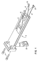
- FIG. 1 is a perspective view of a magnetic head arm assembly;
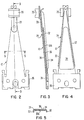
- FIG. 2 is a top plan view of a magnetic head suspension embodying the invention;
- FIG. 3 is a longitudinal section along line 3-3 of FIG. 2;
- FIG. 4 is a bottom plan view of a magnetic head suspension embodying the present invention;
- FIG. 5 is a section on line 5-5 of FIG. 2;
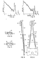
- FIG. 6 is a graph of vibration amplitude versus frequency for a magnetic head suspension without a damping arrangement according to the invention;
- FIG. 7 is a graph of vibration amplitude versus frequencyforthe magnetic head suspension when modified by the inclusion of a damping arrangement in accordance with the embodiment of the invention shown in FIG. 2;
- FIG. 8 is a bottom plan view of another magnetic head suspension embodying the present invention;
- FIG. 9 is a longitudinal section on line 9-9 of FIG 8;
- FIG. 10 is a section on line 10-10 of FIG. 8;
- FIG. 11 is a section on line 11-11 of FIG. 8;
- FIG. 12 is a top plan view of a further magnetic head suspension embodying the present invention;
- FIG. 13 is a longitudinal section on line 13-13 of FIG. 12;
- FIG. 14 is a section on line 14-14 of FIG. 12;
- FIG. 15 is a graph of vibration amplitude vs. frequency for a magnetic head suspension;
- FIG. 16 is a graph of vibration amplitude vs. frequency for the magnetic head suspension of FIG. 15 when modified in accordance with the embodiment of the present invention shown in FIG. 12;
- FIG. 17 is a section of another magnetic head suspension embodying the present invention.
- With reference to FIG. 1, magnetic head suspension assemblies 12 and 14 are attached to the top of a
magnetic head arm 10, and magnetic head suspension assemblies 16 and 18 are attached to the bottom of thehead arm 10. Eachsuspension assembly head slider 20, and eachhead slider 20 has one or more magnetic transducer means disposed so that the transducing gap may be in transducing relation with magnetic disk surfaces. Electrical signals are conducted from the heads to aplug connector assembly 22 for use by a host system.Head arm 10 is attached by threaded screws 9, for example to suitable positioning means as is known in the art. - The structure of each of the suspension assemblies 12, 14, 16, 18 is the same. The structure of
suspension assembly 12 is shown in FIGS. 2 to 5 and this assembly comprises aload beam 24, amounting block 26 and aflexure 28 to supporthead slider 20. Theload beam 24 comprises a spring member having a tapered elongateflat section 30 having upturned edges to produceflanges 32 over part of its length to provide sufficient stiffness to load the magnetic head toward the disk surface. An air bearing force supplied by the air flow adjacent to the disk surface provides an opposing aerodynamic force or pressure to develop a spacing between the head and the disk, or a flying height for the head, which may be about 0.5 microns (20 microinches), by way of example. In this manner, a noncontact transducing relationship between the transducing gap of the magnetic heads and the data tracks of the magnetic disk is established. - Although the head arm assembly constructed as so far described achieves a desired head loading relative to a record surface, resonant frequencies are associated with the components of the assembly due to their design. Vibrations at one or more of these resonant frequencies tend to vary significantly the desired head-to-disk spacing, thereby degrading the read-write process. FIG. 6 is a graphical representation of the typical amplitude of vibration at different frequencies for a specific suspension.
- In accordance with the present invention, one side of a layer (34) of damping material is positioned in intimate contact with an
inboard surface area 30b of the flat section of the load beam. A constraining member is fixed in intimate contact with the other side of the damping layer. This structure significantly reduces the vibration by shear energy absorption in the damping material. The structure is operable to reduce tangential mode vibrations (along the data track), torsional mode vibration, and bending mode vibration. - In the specific embodiment shown in FIGS. 2 to 5, the
damping layer 34 substantially covers thesurface area 30b of the tapered elongateflat section 30.Surface area 30b is on the side ofsection 30 away from the disk surface which is in transducing relation with the attachedhead slider 20. A constrainingmember 36 is fixed in intimate contact with the outer surface ofdamping layer 34 so thatdamping layer 34 is constrained betweenload beam 24 and constrainingmember 36. - The addition of the
layer 34 andmember 36 to the magnetic head suspension reduces the vibration level by shear energy absorption in thedamping layer 34. The suspension whose vibration characteristics were shown in FIG. 6 was modified by adding thedamping layer 34 and the constrainingmember 36 as described above. The level of vibrations for the modified suspension is shown in FIG. 7. Note that the damping was very effective between the 3.0 to 3.5 KHz frequency range in which the vibration level as shown in FIG. 6 exceeded the allowable vibration limits for a particular application. The level of vibration for the suspension modified in accordance with the present invention (FIG. 7) was well within the specifications for that particular application. - The damping
layer 34 may comprise any suitable viscoelastic material, and the dampinglayer 34 may be held in intimate contact with theinboard surface area 30b and constrainingmember 36 by any suitable means such as adhesives or mechanical means. One suitable material for dampinglayer 34 is a modified acrylic polymer material, and such a material is produced in the convenient form of a double-sided tape by the 3M Company, St. Paul, MN., USA under their designation ISD 110. The dampinglayer 34 and constrainingmember 36 are cut to the proper shape and are stuck in position onsurface 30b, as shown in FIG. 5, by the pressure sensitive nature of the tape. The load beam may then be heated to a temperature sufficient to make the viscoelastic material tacky so that the three components are more effectively bonded together, but not to a temperature which would destroy the viscoelastic properties of the polymer material. One suitable treatment comprises applying a pressure of from 1.03 x 10⁵ to 1.38 x 10⁵ pascals (15 to 30 psi) within the range of 93 to 149°C (200-300°F) for about 45 seconds. - An alternative embodiment of the invention is shown in FIG. 8 in which a damping
layer 38 is held in intimate contact with theinboard surface area 30b by a modified constrainingmember 40. The constrainingmember 40 has aflat section 42, which is coextensive withsurface area 30b, and upturned edges to formflanges 44. As shown in FIG. 11, theflanges flanges flanges 44 which is bent outwards to extend to flanges 32. While in this position, thetabs 46 are fixed, by welding, for example, to theflanges 32 so that the dampinglayer 38 is held in intimate contact betweenload beam 24 and constrainingmember 40. Test data shows that this embodiment is also effective to substantially reduce the vibration amplitude over the frequency range shown in FIGS. 6 and 7. - The addition of the damping layer and the constraining member to the suspension does not alter the fundamental design of the suspension, but these components are effective to substantially reduce the tangential mode vibration, the torsional mode vibration as well as the bending mode vibration.
- The embodiments shown in FIGS. 2 to 5 and 8 to 10 are preferred since the damping layer is within the
flanges 32 of the load beam and for that reason does not take up space in the suspension to disk area. However, the damping is equally effective when the damping layer and constraining member are fixed to the surface of the load beam which faces the disk surface which is in transducing relation with the attachedhead slider 20. - The embodiment shown in FIGS. 12 and 13 comprises a damping
layer 50 in intimate contact with thesurface area 30 of theload beam 24. A constrainingmember 52 is positioned in contact with the dampinglayer 50 so that vibrations are damped by shear energy absorption in dampinglayer 50 due to differential movements ofload beam 24 and constrainingmember 52 due to the vibrations. FIGS. 15 (before) and 16 (after) show the effect produced on the vibration amplitude by the addition of the dampinglayer 50 and the constrainingmember 52 to the magnetic head suspension. - The damping layer and the constraining member may be fixed in position by suitable adhesives or by mechanical means. The embodiment shown in FIGS. 12 to 14 can be formed by the use of a pressure sensitive tape and selective heating as was previously described with respect to the embodiment shown in FIGS. 2 to 5.
- The damping structure can also be fixed in place by mechanical means. One suitable embodiment is shown in FIG. 17. In this embodiment, the constraining
member 56 has turned edges to produceflanges 58 which mate withflanges 32 ofload beam 24. A plurality of spaced tabs are produced onflanges 58 so that thetabs 60 can be bent inwards aroundflanges 32 to fix dampingelement 54 and constrainingmember 56 in place. Alternatively dampingelement 54 may extend to the edges of theflanges 58 and eitherflanges 58 or bothflanges - In a specific embodiment which gave damping improvement similar to that shown in FIGS. 7 and 16, the
load beam 24 was made of stainless steel 78 microns (3 mils thick), the viscoelastic damping material was 125 microns (5 mils) thick, and the constrainingmember 36 was made ofstainless steel 50 microns (2 mils) thick.
Claims (7)
Applications Claiming Priority (2)
| Application Number | Priority Date | Filing Date | Title |
|---|---|---|---|
| US48099783A | 1983-03-30 | 1983-03-30 | |
| US480997 | 1983-03-30 |
Publications (2)
| Publication Number | Publication Date |
|---|---|
| EP0121057A1 EP0121057A1 (en) | 1984-10-10 |
| EP0121057B1 true EP0121057B1 (en) | 1990-06-13 |
Family
ID=23910172
Family Applications (1)
| Application Number | Title | Priority Date | Filing Date |
|---|---|---|---|
| EP84101276A Expired - Lifetime EP0121057B1 (en) | 1983-03-30 | 1984-02-08 | Transducer suspension |
Country Status (4)
| Country | Link |
|---|---|
| EP (1) | EP0121057B1 (en) |
| JP (1) | JPS59180855A (en) |
| DE (1) | DE3482517D1 (en) |
| HK (1) | HK139894A (en) |
Cited By (1)
| Publication number | Priority date | Publication date | Assignee | Title |
|---|---|---|---|---|
| US6775104B2 (en) | 2000-09-27 | 2004-08-10 | Seagate Technology Llc | Actuator arm damper with integrated pre-amplifier |
Families Citing this family (24)
| Publication number | Priority date | Publication date | Assignee | Title |
|---|---|---|---|---|
| DE3679480D1 (en) * | 1985-08-22 | 1991-07-04 | Minnesota Mining & Mfg | RECEIVING HEAD AND ARM ARM FOR A STORAGE MEDIUM WITH STRETCHED SURFACE. |
| DE3680667D1 (en) * | 1986-05-23 | 1991-09-05 | Ibm | HEAD / ARM ASSEMBLY AND ROTATING ACCESS MECHANISM FOR A DISK STORAGE. |
| US4819094A (en) * | 1986-08-12 | 1989-04-04 | Oberg Gary R | Damped magnetic head suspension assembly |
| GB2193833B (en) * | 1986-08-12 | 1990-09-19 | Hutchinson Technology | Magnetic head arm assembly |
| KR910001150B1 (en) * | 1986-09-19 | 1991-02-25 | 가부시끼가이샤 히다찌세이사꾸쇼 | Flanged tranducer supporting arm for a magnetic head/arm assembly |
| US4991045A (en) * | 1987-12-21 | 1991-02-05 | Hutchinson Technology, Inc. | Suspension assembly |
| CA2021359C (en) * | 1989-11-13 | 1994-04-12 | Wayne E. Foote | Magnetic head suspension assembly in a disk drive |
| WO1992008242A1 (en) * | 1990-10-25 | 1992-05-14 | Strong Leslie G | Method and apparatus for transporting sensitive electronic components |
| EP0648367B1 (en) * | 1992-07-01 | 1997-10-08 | Ampex Systems Corporation | Pantographic mount for a magnetic transducing head |
| JP2814450B2 (en) * | 1994-03-31 | 1998-10-22 | インターナショナル・ビジネス・マシーンズ・コーポレイション | Head suspension assembly and method of manufacturing the same |
| US5663854A (en) * | 1995-06-07 | 1997-09-02 | International Business Machines Corporation | Prebent ceramic suspension |
| US5859105A (en) * | 1997-02-11 | 1999-01-12 | Johnson Matthey, Inc. | Organosilicon-containing compositions capable of rapid curing at low temperature |
| WO1997035302A1 (en) * | 1996-03-19 | 1997-09-25 | International Business Machines Corporation | Planar head gimbal assembly for pico/nano slider |
| US6046883A (en) * | 1996-12-31 | 2000-04-04 | Hutchinson Technology Incorporated | Head suspension having a flexure motion limiter |
| US5796553A (en) * | 1997-03-31 | 1998-08-18 | Hutchinson Technology Incorporated | Disk drive head suspension having gaps in the load beam which are at least partially filled with or covered by damping material |
| US6021022A (en) * | 1997-10-27 | 2000-02-01 | Seagate Technology, Inc. | Flexure displacement limiter-flex circuit interconnect |
| US6271996B1 (en) | 1997-11-10 | 2001-08-07 | Hutchinson Technology Incorporated | Damper with unconstrained surface for a disk drive head suspension |
| US6005750A (en) * | 1997-11-12 | 1999-12-21 | Hutchinson Technology Incorporated | Head suspension including coupled flexure and damper constraint layer |
| US6704164B1 (en) * | 1999-04-30 | 2004-03-09 | Fujitsu Limited | Vibration reducing members for head suspensions |
| US6172853B1 (en) | 1999-05-20 | 2001-01-09 | Hutchinson Technology Incorporated | Head suspension having a near dimple motion limiter |
| US6353515B1 (en) | 1999-09-20 | 2002-03-05 | Innovex, Inc. | Flex suspension assembly for disk drive |
| JP2001297549A (en) | 2000-04-10 | 2001-10-26 | Nitto Denko Corp | Continuous damping material supply |
| JP4190497B2 (en) | 2002-10-30 | 2008-12-03 | 富士通株式会社 | Actuator for magnetic head and magnetic disk device |
| JP4208253B2 (en) | 2006-09-07 | 2009-01-14 | サンコール株式会社 | Magnetic head suspension and method of manufacturing base for magnetic head suspension |
Citations (1)
| Publication number | Priority date | Publication date | Assignee | Title |
|---|---|---|---|---|
| EP0007401A1 (en) * | 1978-07-27 | 1980-02-06 | International Business Machines Corporation | Magnetic transducer head support assemblies |
Family Cites Families (5)
| Publication number | Priority date | Publication date | Assignee | Title |
|---|---|---|---|---|
| DE2730719C2 (en) * | 1977-07-07 | 1986-02-20 | Basf Ag, 6700 Ludwigshafen | Device for the automatic loading / unloading of a magnetic head in a magnetic disk drive |
| FR2420809A1 (en) * | 1978-03-24 | 1979-10-19 | Cii Honeywell Bull | READ-WRITE DEVICE FOR AN INFORMATION MEDIA WITH LOW-LOAD RAMP TAKING |
| US4175275A (en) * | 1978-05-22 | 1979-11-20 | International Business Machines Corporation | R/W Arm that prevents catastrophic failure |
| JPS5619554A (en) * | 1979-07-23 | 1981-02-24 | Nec Corp | Supporting arm of magnetic head slider |
| DE3167267D1 (en) * | 1981-03-18 | 1985-01-03 | Ibm | Head support arm and head/arm assemblies for disk files |
-
1984
- 1984-01-18 JP JP586984A patent/JPS59180855A/en active Granted
- 1984-02-08 DE DE8484101276T patent/DE3482517D1/en not_active Expired - Lifetime
- 1984-02-08 EP EP84101276A patent/EP0121057B1/en not_active Expired - Lifetime
-
1994
- 1994-12-08 HK HK139894A patent/HK139894A/en not_active IP Right Cessation
Patent Citations (1)
| Publication number | Priority date | Publication date | Assignee | Title |
|---|---|---|---|---|
| EP0007401A1 (en) * | 1978-07-27 | 1980-02-06 | International Business Machines Corporation | Magnetic transducer head support assemblies |
Non-Patent Citations (2)
| Title |
|---|
| Bolasna et al, "Air-Bearing Support of a Magnetic Recording Head", published at pages 12 to 15 of IBM Disk Storage Technology published by IBM,General Products Division, 5600 Cottle Road, San Jose, Calif., USA Order Number GA 26-1665-0 * |
| Harker et al, "A Quarter Century of Disk File Innovation" published at pages 677 to 689 of IBM Journal of Research and Development (25th AnniversaryIssue), vol 25, no 5, September 1981 * |
Cited By (1)
| Publication number | Priority date | Publication date | Assignee | Title |
|---|---|---|---|---|
| US6775104B2 (en) | 2000-09-27 | 2004-08-10 | Seagate Technology Llc | Actuator arm damper with integrated pre-amplifier |
Also Published As
| Publication number | Publication date |
|---|---|
| EP0121057A1 (en) | 1984-10-10 |
| JPS59180855A (en) | 1984-10-15 |
| JPH048868B2 (en) | 1992-02-18 |
| HK139894A (en) | 1994-12-16 |
| DE3482517D1 (en) | 1990-07-19 |
Similar Documents
| Publication | Publication Date | Title |
|---|---|---|
| US4760478A (en) | Visco-elastically damped magnetic head suspension assembly | |
| EP0121057A1 (en) | Transducer suspension | |
| US4408238A (en) | Magnetic head arm assembly | |
| KR100400039B1 (en) | Head gimbal assembly and method of reducing vibration of head actuation assembly | |
| EP0362072B1 (en) | A mechanism for suspending a head slider of a recording apparatus | |
| US4734805A (en) | Magnetic head supporting mechanism | |
| US6215623B1 (en) | Dynamic-absorber for the suppression of suspension vibrations | |
| JP3865684B2 (en) | Hard disk drive | |
| US7064931B2 (en) | Disc drive suspension optimized for preload bend damper | |
| US5057953A (en) | Head slider suspension assembly load beam having a fundamental mode vibration characteristic in the range of about 2000 hertz to about 4000 hertz | |
| US5831793A (en) | Suspension assembly shock absorber | |
| US4933791A (en) | Head arm flexure for disc drives | |
| CA1147854A (en) | Suspension for air bearing head arm assembly | |
| EP0155746A1 (en) | Arch flexure for winchester sliders | |
| US20030169537A1 (en) | Armature vibration damper for an armature in a disc storage system | |
| US5712748A (en) | Slider-suspension in a disc drive | |
| US6108174A (en) | Tuning actuator arm displacement characteristics to reduce damage from mechanical shocks | |
| US6215627B1 (en) | Suspension assembly gimbal load beam stiffener | |
| US11557318B1 (en) | Head gimbal assembly, manufacturing method thereof, and disk drive unit | |
| US6674601B1 (en) | Method and apparatus for electronically shifting mechanical resonance of an actuator system of a disc drive | |
| US12620413B2 (en) | Profile shape control for gimbal assembly | |
| JPS6161190B2 (en) | ||
| EP0246375B1 (en) | Head/arm assembly and rotary access mechanism for a disk file | |
| KR930001102Y1 (en) | Recording Head and Support Arm Assembly for Elongated Recording Media | |
| JP3289307B2 (en) | Magnetic disk drive |
Legal Events
| Date | Code | Title | Description |
|---|---|---|---|
| PUAI | Public reference made under article 153(3) epc to a published international application that has entered the european phase |
Free format text: ORIGINAL CODE: 0009012 |
|
| AK | Designated contracting states |
Designated state(s): DE FR GB |
|
| 17P | Request for examination filed |
Effective date: 19841123 |
|
| 17Q | First examination report despatched |
Effective date: 19860303 |
|
| D17Q | First examination report despatched (deleted) | ||
| GRAA | (expected) grant |
Free format text: ORIGINAL CODE: 0009210 |
|
| AK | Designated contracting states |
Kind code of ref document: B1 Designated state(s): DE FR GB |
|
| REF | Corresponds to: |
Ref document number: 3482517 Country of ref document: DE Date of ref document: 19900719 |
|
| ET | Fr: translation filed | ||
| PLBE | No opposition filed within time limit |
Free format text: ORIGINAL CODE: 0009261 |
|
| STAA | Information on the status of an ep patent application or granted ep patent |
Free format text: STATUS: NO OPPOSITION FILED WITHIN TIME LIMIT |
|
| 26N | No opposition filed | ||
| PGFP | Annual fee paid to national office [announced via postgrant information from national office to epo] |
Ref country code: FR Payment date: 19960131 Year of fee payment: 13 |
|
| PG25 | Lapsed in a contracting state [announced via postgrant information from national office to epo] |
Ref country code: FR Effective date: 19971030 |
|
| REG | Reference to a national code |
Ref country code: FR Ref legal event code: ST |
|
| REG | Reference to a national code |
Ref country code: GB Ref legal event code: IF02 |
|
| PGFP | Annual fee paid to national office [announced via postgrant information from national office to epo] |
Ref country code: DE Payment date: 20021230 Year of fee payment: 20 |
|
| PGFP | Annual fee paid to national office [announced via postgrant information from national office to epo] |
Ref country code: GB Payment date: 20030203 Year of fee payment: 20 |
|
| PG25 | Lapsed in a contracting state [announced via postgrant information from national office to epo] |
Ref country code: GB Free format text: LAPSE BECAUSE OF EXPIRATION OF PROTECTION Effective date: 20040207 |
|
| REG | Reference to a national code |
Ref country code: GB Ref legal event code: 732E |
|
| REG | Reference to a national code |
Ref country code: GB Ref legal event code: PE20 |
|
| APAH | Appeal reference modified |
Free format text: ORIGINAL CODE: EPIDOSCREFNO |