EP0120656B1 - Apparatus for removing water from the ground - Google Patents
Apparatus for removing water from the ground Download PDFInfo
- Publication number
- EP0120656B1 EP0120656B1 EP84301781A EP84301781A EP0120656B1 EP 0120656 B1 EP0120656 B1 EP 0120656B1 EP 84301781 A EP84301781 A EP 84301781A EP 84301781 A EP84301781 A EP 84301781A EP 0120656 B1 EP0120656 B1 EP 0120656B1
- Authority
- EP
- European Patent Office
- Prior art keywords
- cylinder
- apertures
- water
- drum
- layer
- Prior art date
- Legal status (The legal status is an assumption and is not a legal conclusion. Google has not performed a legal analysis and makes no representation as to the accuracy of the status listed.)
- Expired
Links
- XLYOFNOQVPJJNP-UHFFFAOYSA-N water Substances O XLYOFNOQVPJJNP-UHFFFAOYSA-N 0.000 title claims description 97
- 229920001971 elastomer Polymers 0.000 claims description 17
- 239000000463 material Substances 0.000 claims description 9
- 230000005484 gravity Effects 0.000 claims description 4
- 239000012858 resilient material Substances 0.000 claims description 2
- 230000008878 coupling Effects 0.000 claims 1
- 238000010168 coupling process Methods 0.000 claims 1
- 238000005859 coupling reaction Methods 0.000 claims 1
- 229920001821 foam rubber Polymers 0.000 description 20
- 230000008901 benefit Effects 0.000 description 6
- 230000006378 damage Effects 0.000 description 5
- 239000006260 foam Substances 0.000 description 5
- 244000025254 Cannabis sativa Species 0.000 description 4
- 230000006835 compression Effects 0.000 description 3
- 238000007906 compression Methods 0.000 description 3
- 230000000694 effects Effects 0.000 description 3
- 235000021384 green leafy vegetables Nutrition 0.000 description 3
- 239000004033 plastic Substances 0.000 description 3
- 208000027418 Wounds and injury Diseases 0.000 description 2
- 238000010276 construction Methods 0.000 description 2
- 239000003673 groundwater Substances 0.000 description 2
- 238000000034 method Methods 0.000 description 2
- 238000005086 pumping Methods 0.000 description 2
- 239000002352 surface water Substances 0.000 description 2
- 238000010521 absorption reaction Methods 0.000 description 1
- 230000000386 athletic effect Effects 0.000 description 1
- 208000014674 injury Diseases 0.000 description 1
- 238000012423 maintenance Methods 0.000 description 1
- 239000011295 pitch Substances 0.000 description 1
- 239000011148 porous material Substances 0.000 description 1
- 229910001220 stainless steel Inorganic materials 0.000 description 1
- 239000010935 stainless steel Substances 0.000 description 1
Images





Classifications
-
- E—FIXED CONSTRUCTIONS
- E01—CONSTRUCTION OF ROADS, RAILWAYS, OR BRIDGES
- E01H—STREET CLEANING; CLEANING OF PERMANENT WAYS; CLEANING BEACHES; DISPERSING OR PREVENTING FOG IN GENERAL CLEANING STREET OR RAILWAY FURNITURE OR TUNNEL WALLS
- E01H1/00—Removing undesirable matter from roads or like surfaces, with or without moistening of the surface
- E01H1/10—Hydraulically loosening or dislodging undesirable matter; Raking or scraping apparatus ; Removing liquids or semi-liquids e.g., absorbing water, sliding-off mud
- E01H1/108—Removing liquids or semi- liquids, e.g. absorbing rain water, sucking-off mud
-
- F—MECHANICAL ENGINEERING; LIGHTING; HEATING; WEAPONS; BLASTING
- F02—COMBUSTION ENGINES; HOT-GAS OR COMBUSTION-PRODUCT ENGINE PLANTS
- F02B—INTERNAL-COMBUSTION PISTON ENGINES; COMBUSTION ENGINES IN GENERAL
- F02B1/00—Engines characterised by fuel-air mixture compression
- F02B1/02—Engines characterised by fuel-air mixture compression with positive ignition
- F02B1/04—Engines characterised by fuel-air mixture compression with positive ignition with fuel-air mixture admission into cylinder
Definitions
- This invention concerns an apparatus for the removal of surface water and limited sub-surface water from the ground, the floor or the like surfaces hereinafter referred to collectively as the ground.
- the apparatus is adapted to remove water from sports fields including football. pitches, athletic grounds, cricket grounds, bowling greens, race tracks, golf courses and is particularly suitable for use with grass covered surfaces. Sporting events are frequently cancelled or abandoned due to water logging. Others are held in very soggy conditions to the disadvantage of the sport concerned both from the player's and spectator's points of view.
- Plastic sheeting has been tried unsuccessfully as a method of protecting the ground but the main difficulty here has been removing the plastic sheeting, with the weight of water on it. Also of course, plastic sheeting cannot withstand even mqderate winds without lifting and/or tearing. This is combined with the failure to find a satisfactory method of joining the sheets to avoid seepage at the joints.
- the known apparatus comprises a perforated cylinder mounted on a handled frame for rotation over the ground, the cylinder being covered by a layer of water absorptive material and the said layer of material being provided with a plurality of holes and/or grooves to facilitate ease of water absorption by the said layer, a second cylinder being provided on the frame to squeeze water from the material layer such that said water passes down through the perforated cylinder into a container housed within the perforated cylinder.
- the known apparatus provides that the water collected by the layer of absorptive material enters the cylinder only at the top of the rotating cylinder in that the water is squeezed from the material and falls under gravity into the cylinder.
- the present invention has the added advantages over the known art that the water is positively collected at the lower region of the drum by the provision of valve means in the drum and also where the resilient layer is provided with channels and/or apertures the water is pumped directly via the valve means into the drum by the compressive action of the ground on the resilient layer of open cell material.
- the present invention provides an apparatus for the removal of water from the ground, comprising at least one ground-engaging drum including a hollow cylinder mounted for rotation about a horizontal axis, a plurality of apertures distributed around the circumference of the cylinder and a layer of resilient material covering the outer surface of the cylinder, the resilient layer including means distributed around its circumference to permit the passage of water through the resilient layer to the cylinder, and a non-rotating water tank mounted within the cylinder, characterised in that valve means in the drum are arranged to close the apertures, at least in respect of the lower region of the drum, except under the inward pressure of water passing through the resilient layer when the latter is compressed, and a plurality of troughs on the inner surface of the cylinder being provided for carrying water which enters the apertures in the area of ground contact upwardly away from the ground by rotation of the cylinder, said water tank being provided for collecting water discharged from the troughs when each reaches a certain height.
- the present invention has the advantage that there is no need to cover the ground to protect it from excessive rain, as the apparatus can traverse even the soggiest ground without injury to it whilst at the same time collecting the water as it travels, by both pressure and suction from the base of the grass, leaving it in a relatively dry condition.
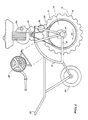
- the apparatus comprises a ground-engaging drum 10 mounted in a frame 11 for rotation about a horizontal axis. More specifically, the drum 10 comprises an inner cylinder 12 of stainless steel or extruded PVC which is rotatably mounted on a fixed horizontal shaft 13, the latter passing coaxially through the cylinder 12 ( Figure 3) and being supported at each end in respective mountings 14 carried at opposite sides 15, 16 of the frame 11.
- the drum 10 comprises an inner cylinder 12 of stainless steel or extruded PVC which is rotatably mounted on a fixed horizontal shaft 13, the latter passing coaxially through the cylinder 12 ( Figure 3) and being supported at each end in respective mountings 14 carried at opposite sides 15, 16 of the frame 11.
- the cylinder 12 is apertured around its circumference, the apertures 17 either being circular as shown in figures 3 and 7 or, more preferably, elongate slots as shown in figure 8.
- the apertures 17 are arranged in rows which extend across the full width of the cylinder parallel to its axis of rotation, the rows being equally spaced around the circumference of the cylinder.
- the apertures 17 are staggered from one row to the next, each aperture of a given row being positioned intermediate a pair of apertures in the rows immediately on either side. In the case of slotted apertures, fig. 8, these are aligned in the direction of their respective rows.
- the drum 10 is driven for rotation by a petrol engine 20 mounted atop the frame 11, the cylinder 12 being coupled to the engine 20 by a reduction gear 21 and a chain drive 22.
- the right hand side of figure 1 constitutes the front of the apparatus and therefore the drum 10 is driven in the direction of the arrow 23.
- the apparatus is stabilised by a balance cylinder 24 carried by the frame 11 behind the drum 10, and the whole apparatus is manually guided by a handle 25 at the rear.
- a single flap valve 26 could be used to close off two or more rows of apertures 17 rather than only a single row as described.
- the flap valves could be springloaded or otherwise biassed in any conventional manner against the row of apertures 17.
- the action of the flap valves in closing off the apertures 17 could be gravity-assisted, since it is only necessary that they be effective in the lower region of the drum 10 as will be described.
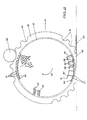
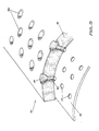
- the inside of the cylinder 12 is also provided with a plurality of ducts or troughs 30, figs. 6 and 7, each trough extending parallel to the axis of rotation of the cylinder, and there being one such trough for each pair of adjacent rows of apertures 17 as shown in Figure 6.
- Each trough 30 has an L-shaped cross-section with one longitudinal edge secured to the inner surface of the cylinder adjacent to a respective row of apertures 17, and the other (free) edge 31 being disposed inwardly of the inner surface of the cylinder and angularly displaced in the direction of rotation of the cylinder.
- the troughs 30 extend the full length of the cylinder 12 and are closed off at each end by the inside surfaces of the circular endwalls 32 (fig. 3) of the cylinder. It will be recognised that an individual trough 30 could be provided for each row of apertures 17 if desired, rather than providing one trough for each two adjacent rows as in this embodiment.
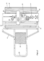
- the apparatus further includes a water tank 35 of part cylindrical cross-section, see figures 3 and 4, the tank 35 being mounted on the shaft 13 by bearings 36. It will be understood that the tank 35 does not rotate with the drum 10. As will be described, the purpose of the tank 35 is to collect water which initially enters the apertures 17 from the foam rubber layer 18 in the area of contact with the ground and which is thereafter transported upwardly by the troughs 30. The tank 35 also collects water squeezed from the layer 18 by a pressure roller 36, figs. 1, 2, 5 and 6, the roller 36 being rotatably mounted between the opposite sides 15, 16 of the frame 11 and being driven by the chain drive 22.
- the water which is collected in the tank 35 may be removed by a pump 45 mounted on the top of the frame 11.
- the pump 45 acts in a conventional manner to draw the water from the tank 35 through a discharge pipe 47 into the shaft 13 which is hollow, a rotary hose reel 46 being mounted on the frame 11 and operatively connected to a water outlet end (not shown) of the shaft 13.
- the apparatus operates as follows.
- the drum 10 When the engine 20 is running the drum 10 is rotated in the direction of the arrow 40 and is thus propelled forwardly in the direction of the arrow 41.
- the layer 18 In the area of ground contact 42 in front of a notional vertical centre plane intersecting the axis of the drum 10, the layer 18 is subject to increasing compression as the drum moves forward.
- the ground water 43 In this area 42 the ground water 43 is first trapped in the grooves or channels 19 and, as the layer 18 compresses, the water is forced under pressure inwardly inwards the cylinder 12 through the open cell structure of the layer 18.
- each trough will begn to discharge its water as shown for the trough 30' in figure 6.
- the opening at the top of the water tank 35 (not shown in figure 6) is sufficiently wide to collect this water as it drains from the troughs 30. It is of course to be understood that figure 6 has been considerably simplified, and that the apertures 17, flap valves 26 and troughs 30 are provided around the entire circumference of the cylinder 12 as hereinbefore described.
- the open cell foam rubber 18 will effectively collect additional water and dry the grass to a considerable extent behind the drum as it rolls forward, since residual water and moisture is collected by the foam rubber 18 after it has passed the notional centre plane referred to above, i.e. after the point of maximum compression with the ground.
- This additional collection of water results from the fact that when the pressure on the foam rubber 18 is released, a strong suction is created as the cylinder apertures 17 are sealed off by the flap valves 26 thereby allowing the open cells of the foam rubber to suck in water.
- the water is pumped out from the bottom of the tank 35 by means of the pipe 47, the hollow shaft 13 and the hose reel 46.
- the necessary length of say 30.5 centimetres (1 foot) water hose is carried on the rotary hose reel 46 (fig. 1) mounted on top of the apparatus.
- This hose reel can be wound in or out as required, the hose of course being connected to the drain point nearest the area being cleared of water.
- the apparatus can of course be adapted in design to carry a cab section with drivers seat.
- the second smaller balancing cylinder 24 running behind the drum 10 is covered with high density closed cell foam rubber, PVC or other suitable material.
- This smaller guide cylinder does not carry any appreciable weight as its function is only as a balancing guide/steering roller.
- the foam rubber 18 will protect the ground from damage by the machine as the weight of the drum 10 and ancillary equipment is spread over a relatively flat area at the point of contact with the ground. This feature is vitally important in the case of football ground, golf greens, etc. where it would be impossible to allow any conventional machinery to traverse the ground in soggy conditions.
- the foam rubber 18 also effectively eliminates the effect of bumpy or eneven ground as, in the cases of recesses, the rubber expands into them and in the case of protrusions or bumps, it will compress to the necessary degree.
- the cylinder is capable of carrying the weight of the necessary equipment, i.e. engine, reduction gear, water pump, hose reel, etc. without risk of damage to the ground.
- the longitudinal channels 19 of the first embodiment are replaced by individual apertures 50 which extend fully through the thickness of the layer 18 of open cell foam rubber, each aperture 50 being in register with and communicating directly with a respective aperture 17 in the cylinder 12.
- the apertures 50 are preferably in the form of funnels as shown, having a relatively large cup-like outer portion 51 at the outer surface of the layer 18 which tapers inwardly to a cylindrical inner portion 52 having a width substantially the same as that of the respective circular aperture 17 in the cylinder 12.
- the apertures 17 are arranged in staggered rows across the width of the cylinder 12, and the apertures 50 are therefore similarly located in the layer 18.
- the cup-like portions 51 of the apertures 50 preferably have about the same width 5.1 cm (2 inches) at the outer surface of the layer 18 as the channels 19 previously provided, and since the apertures 50 correspond one-to-one to the apertures 17, the latter are somewhat larger and less in number than before.
- the cylinder 12 has fewer rows of apertures 17 with fewer apertures in each row. For this reason, as shown in figure 3, only one row of apertures 17 and one flap valve 26 is provided between each adjacent pair of troughs 30.
- a further embodiment of the invention provides a sheet of non-porous rubber 60 or the like non-porous material which is bonded in a conventional manner to the outer surface 61 of the open cell foam rubber layer 18, the rubber sheet 60 being provided with a plurality of apertures 62 which are in register with the apertures 50 in the open cell foam rubber layer 18.
- a rubber sheet 60 of 1.59 millimetres (1/16 inch) thickness is appropriate.
- the rubber sheet 60 is sufficiently resilient to make it together with the foam rubber layer 18 a cover unit for the drum 10 which in use will retract under pressure to enhance the pumping action in front and at the bottom of the cylinder 12 as it traverses the ground and expands to suck up any residue of water through the apertures 17 at the rear of the rotating cylinder 12.
- the effect of the rubber sheet 60 covering is that, when the cylinder 12 rotates each row of apertures 50/62 traps the water as it rolls forward.
- the non-porous rubber sheet 60 forces the water to flow into the apertures 50/62 since the water under pressure will of course run to the area of least resistance, namely the nearest aperture 50/62 to each flat area of the open cell foam rubber layer 18.
- a further advantage of the bonded rubber sheet surface covering is that it will protect the open cell foam layer 18 on the cylinder 12 from damage and wear, thereby prolonging the wearability of the entire cylinder covering. Because of the smooth surface which the rubber sheet covering imparts to the drum it greatly improves the turning facility of the machine in use, without any consequent damage to a grass covered ground.
- the rubber sheet covering strengthens the open cell foam layer and enables it to carry a greater weight, while allowing the layer to flatten out at ground level to gain a substantial load and weight spread.
- This low compression has been found to be particularly important in relation to golf course greens for example where the maintenance of a smooth true ground surface is essential.
- the use of the non-porous rubber sheet 60 directs the water under pressure more efficiently into the funnel shaped apertures 50/62 than in the case where the sheet 60 is absent, it is not necessary that the resilient foam rubber layer 18 be of open cell structure. Indeed, the sheet 60 prevents water from entering the body of the layer 18 except at the edges of the apertures 50/62, so that the amount of water absorbed in this way is much less than in the case where the sheet 60 is absent.
- the pressure roller 36 figure 1, may also be omitted in this case.
- FIG. 13 and 14 of the accompanying drawings there is illustrated a fourth embodiment of the apparatus of the present invention.
- This embodiment provides for a fully motorised version of the apparatus and includes the provision of a base chassis 70 upon which four rollers 71, 72, 73 and 74 are provided in pairs both front and rear in a spaced-apart and side-by-side relationship.
- the chassis 70 also carries on support bars 70a a water tank 75 mounted intermediate the pairs of roller 71, 72 and 73, 74 and into which water collected in use by the pairs of rollers may drain as hereinafter described.
- the chassis 70 also carries a drivers seat 76, a conventional steering mechanism 77 operatively connected to the front pair of rollers 71, 72 a drive motor 78 operatively connected by a chain drive (not shown) to the driven rear pair of rollers 73, 74 a differential mechanism (not shown) mounted intermediate the ends of the drive shaft of the rear pair of rollers, and a pump 79 to discharge water from the water tank 75 through a pipe 79a to the pump 79 and then to a discharge nozzle 80.
- the rollers 71, 72, 73, 74 are each of a construction as described in relation to the earlier embodiments.
- the water collected by the rollers 71, 72, 73, 74 in this embodiment drains under gravity from the collector tank in each roller through water feed pipes to the water tank 75.
- the drainage is via the hollow shaft on which the rollers are mounted to the water feed pipe 81 connected between one end 82 of the hollow shaft and the water tank 75.
- the rear rollers 73, 74 discharge the collected water to a water feed pipe 83 connected to the hollow drive shaft, at a point between the rollers, and the water tank 75.
- the water in the water tank 75 may be pumped away through a high velocity discharge nozzle 80 which will throw the water a distance from the ground being cleared of water or pass the water through a long hose line (not shown) which may be connected to the pump outlet to discharge the water away from the area being cleared of water. It is envisaged that this embodiment of the apparatus of the invention can when operating in water at a depth of 5 cms lift and discharge 0.45 cubic metres/min (100 gals/min).
Landscapes
- Engineering & Computer Science (AREA)
- Architecture (AREA)
- Civil Engineering (AREA)
- Structural Engineering (AREA)
- Soil Working Implements (AREA)
- Road Paving Structures (AREA)
- Removal Of Floating Material (AREA)
Description
- This invention concerns an apparatus for the removal of surface water and limited sub-surface water from the ground, the floor or the like surfaces hereinafter referred to collectively as the ground. For example the apparatus is adapted to remove water from sports fields including football. pitches, athletic grounds, cricket grounds, bowling greens, race tracks, golf courses and is particularly suitable for use with grass covered surfaces. Sporting events are frequently cancelled or abandoned due to water logging. Others are held in very soggy conditions to the disadvantage of the sport concerned both from the player's and spectator's points of view.
- Plastic sheeting has been tried unsuccessfully as a method of protecting the ground but the main difficulty here has been removing the plastic sheeting, with the weight of water on it. Also of course, plastic sheeting cannot withstand even mqderate winds without lifting and/or tearing. This is combined with the failure to find a satisfactory method of joining the sheets to avoid seepage at the joints.
- An apparatus for removing water from the ground, for example a tennis court, is known from Swiss Patent Specification 459 281. The known apparatus comprises a perforated cylinder mounted on a handled frame for rotation over the ground, the cylinder being covered by a layer of water absorptive material and the said layer of material being provided with a plurality of holes and/or grooves to facilitate ease of water absorption by the said layer, a second cylinder being provided on the frame to squeeze water from the material layer such that said water passes down through the perforated cylinder into a container housed within the perforated cylinder.
- The known apparatus provides that the water collected by the layer of absorptive material enters the cylinder only at the top of the rotating cylinder in that the water is squeezed from the material and falls under gravity into the cylinder. The present invention has the added advantages over the known art that the water is positively collected at the lower region of the drum by the provision of valve means in the drum and also where the resilient layer is provided with channels and/or apertures the water is pumped directly via the valve means into the drum by the compressive action of the ground on the resilient layer of open cell material.
- Accordingly, the present invention provides an apparatus for the removal of water from the ground, comprising at least one ground-engaging drum including a hollow cylinder mounted for rotation about a horizontal axis, a plurality of apertures distributed around the circumference of the cylinder and a layer of resilient material covering the outer surface of the cylinder, the resilient layer including means distributed around its circumference to permit the passage of water through the resilient layer to the cylinder, and a non-rotating water tank mounted within the cylinder, characterised in that valve means in the drum are arranged to close the apertures, at least in respect of the lower region of the drum, except under the inward pressure of water passing through the resilient layer when the latter is compressed, and a plurality of troughs on the inner surface of the cylinder being provided for carrying water which enters the apertures in the area of ground contact upwardly away from the ground by rotation of the cylinder, said water tank being provided for collecting water discharged from the troughs when each reaches a certain height.
- The present invention has the advantage that there is no need to cover the ground to protect it from excessive rain, as the apparatus can traverse even the soggiest ground without injury to it whilst at the same time collecting the water as it travels, by both pressure and suction from the base of the grass, leaving it in a relatively dry condition.
- Embodiments of the invention will now be described, by way of example with reference to the accompanying drawings in which:
- Fig. 1 is a side view of a first embodiment of an apparatus according to the invention,
- Fig. 2 is a top plan view of the apparatus of Figure 1,
- Fig. 3 is a partially cut-away side view of the apertured cylinder and water tank forming part of the apparatus of Figure 1,
- Fig. 4 is a cross-sectional view of Figure 3,
- Fig. 5 is a cross-sectional view of the water- collecting drum and pressure roller forming part of the apparatus of Figure 1,
- Fig. 6 is a more detailed cross-sectional view of the drum and pressure roller to illustrate the principle of operation.
- Fig. 7 is a partial perspective view of a trough and flap valves forming part of the drum of Figure 6,
- Fig. 8 is an alternative arrangement for the apertures in the cylinder of Figure 3,
- Fig. 9 is a cut-away perspective view of a portion of the ground engaging drum of a second embodiment of the invention,
- Fig. 10 is a cross-sectional view of the drum of Figure 9,
- Fig. 11 is a cut-away perspective view of a portion of the ground engaging drum of a further embodiment of the invention,
- Fig. 12 is a cross-sectional view of the drum of Figure 11,
- Fig. 13 is a perspective view of a fourth embodiment of an apparatus according to the invention, and
- Fig. 14 is a side view of the apparatus as illustrated in Fig. 13.
- Referring to Figures 1 and 2 of the drawings, the apparatus comprises a ground-
engaging drum 10 mounted in aframe 11 for rotation about a horizontal axis. More specifically, thedrum 10 comprises aninner cylinder 12 of stainless steel or extruded PVC which is rotatably mounted on a fixedhorizontal shaft 13, the latter passing coaxially through the cylinder 12 (Figure 3) and being supported at each end inrespective mountings 14 carried atopposite sides frame 11. - The
cylinder 12 is apertured around its circumference, theapertures 17 either being circular as shown in figures 3 and 7 or, more preferably, elongate slots as shown in figure 8. In either case theapertures 17 are arranged in rows which extend across the full width of the cylinder parallel to its axis of rotation, the rows being equally spaced around the circumference of the cylinder. Theapertures 17 are staggered from one row to the next, each aperture of a given row being positioned intermediate a pair of apertures in the rows immediately on either side. In the case of slotted apertures, fig. 8, these are aligned in the direction of their respective rows. - Finally, the
drum 10 comprises anouter layer 18 of open cell foam rubber, preferably about two inches in depth, covering the outer surface of thecylinder 12. The outer surface of thislayer 18 is itself corrugated to define longitudinal grooves orchannels 19 parallel to the axis of rotation of thecylinder 12 and equally spaced circumferentially around thedrum 10. Thegrooves 19 are semicircular in cross-section and about one inch in depth. - The
drum 10 is driven for rotation by apetrol engine 20 mounted atop theframe 11, thecylinder 12 being coupled to theengine 20 by areduction gear 21 and achain drive 22. The right hand side of figure 1, as viewed in the drawing, constitutes the front of the apparatus and therefore thedrum 10 is driven in the direction of the arrow 23. The apparatus is stabilised by abalance cylinder 24 carried by theframe 11 behind thedrum 10, and the whole apparatus is manually guided by ahandle 25 at the rear. - Inside the
cylinder 12 each row ofapertures 17 has an associated elongaterubber flap valve 26, as shown in figures 6 and 7. Although theflap valves 26 are shown only in schematic form it is to be understood that in this embodiment they are attached at each end edge to the inner surface of thecylinder 12 and are so attached that eachflap valve 26 is slightly stretched along its length, and eachvalve 26 is in this manner biassed to close the row ofapertures 17 associated therewith. Such biassing is effected solely through the longitudinal tensioning of each flap valve and the closure of theapertures 17 is therefore maintained for all angular positions of the drum 10 (except when subject to inward water pressure as will be described). Theflap valves 26 may be readily opened when water pressure is applied thereto and will readily close again once the action of water pressure thereon ceases. It is to be understood that, if desired, asingle flap valve 26 could be used to close off two or more rows ofapertures 17 rather than only a single row as described. Also, the flap valves could be springloaded or otherwise biassed in any conventional manner against the row ofapertures 17. Furthermore, it is to be understood that the action of the flap valves in closing off theapertures 17 could be gravity-assisted, since it is only necessary that they be effective in the lower region of thedrum 10 as will be described. - The inside of the
cylinder 12 is also provided with a plurality of ducts ortroughs 30, figs. 6 and 7, each trough extending parallel to the axis of rotation of the cylinder, and there being one such trough for each pair of adjacent rows ofapertures 17 as shown in Figure 6. Eachtrough 30 has an L-shaped cross-section with one longitudinal edge secured to the inner surface of the cylinder adjacent to a respective row ofapertures 17, and the other (free)edge 31 being disposed inwardly of the inner surface of the cylinder and angularly displaced in the direction of rotation of the cylinder. Thetroughs 30 extend the full length of thecylinder 12 and are closed off at each end by the inside surfaces of the circular endwalls 32 (fig. 3) of the cylinder. It will be recognised that anindividual trough 30 could be provided for each row ofapertures 17 if desired, rather than providing one trough for each two adjacent rows as in this embodiment. - The apparatus further includes a
water tank 35 of part cylindrical cross-section, see figures 3 and 4, thetank 35 being mounted on theshaft 13 bybearings 36. It will be understood that thetank 35 does not rotate with thedrum 10. As will be described, the purpose of thetank 35 is to collect water which initially enters theapertures 17 from thefoam rubber layer 18 in the area of contact with the ground and which is thereafter transported upwardly by thetroughs 30. Thetank 35 also collects water squeezed from thelayer 18 by apressure roller 36, figs. 1, 2, 5 and 6, theroller 36 being rotatably mounted between theopposite sides frame 11 and being driven by thechain drive 22. - Referring to figs. 1 and 3 of the accompanying drawings the water which is collected in the
tank 35 may be removed by apump 45 mounted on the top of theframe 11. Thepump 45 acts in a conventional manner to draw the water from thetank 35 through adischarge pipe 47 into theshaft 13 which is hollow, arotary hose reel 46 being mounted on theframe 11 and operatively connected to a water outlet end (not shown) of theshaft 13. - Referring now in particular but not exclusively to figure 6, the apparatus operates as follows. When the
engine 20 is running thedrum 10 is rotated in the direction of thearrow 40 and is thus propelled forwardly in the direction of thearrow 41. In the area ofground contact 42 in front of a notional vertical centre plane intersecting the axis of thedrum 10, thelayer 18 is subject to increasing compression as the drum moves forward. In thisarea 42 theground water 43 is first trapped in the grooves orchannels 19 and, as thelayer 18 compresses, the water is forced under pressure inwardly inwards thecylinder 12 through the open cell structure of thelayer 18. - This inward pressure of the water in the progressively compressed
layer 18 forces theflap valves 26 open in this area (see for example the valves 26'), and the ground water passes into the interior of thecylinder 12. When thevalves 26 pass the notional vertical centre plane the adjacentfoam rubber layer 18 now progressively decompresses so that the inward water pressure is relieved and thevalves 26 close. - The water which entered the
cylinder 12 is now trapped in thetroughs 30 and is carried rearwardly and upwardly upon further rotation of thedrum 10. At a certain height, depending upon the amount of water collected in each trough and the geometric dimensions of the apparatus, each trough will begn to discharge its water as shown for the trough 30' in figure 6. The opening at the top of the water tank 35 (not shown in figure 6) is sufficiently wide to collect this water as it drains from thetroughs 30. It is of course to be understood that figure 6 has been considerably simplified, and that theapertures 17,flap valves 26 andtroughs 30 are provided around the entire circumference of thecylinder 12 as hereinbefore described. - In addition to the ability of the apparatus as described above to collect bulk water in advance of the drum 120, another feature of the apparatus is that the open cell foam rubber 18will effectively collect additional water and dry the grass to a considerable extent behind the drum as it rolls forward, since residual water and moisture is collected by the
foam rubber 18 after it has passed the notional centre plane referred to above, i.e. after the point of maximum compression with the ground. This additional collection of water results from the fact that when the pressure on thefoam rubber 18 is released, a strong suction is created as thecylinder apertures 17 are sealed off by theflap valves 26 thereby allowing the open cells of the foam rubber to suck in water. As thecylinder 12 rotates, the water in thefoam rubber 18 is carried to the top of the cylinder when it is squeezed back through theflap valves 26 and theapertures 17 in the cylinder and into thecentral water tank 35. This is attained by means of thepressure roller 36 driven by thechain drive 22 to run against thefoam rubber 18, applying a pre-determined pressure and effectively pressing the water out of the foam rubber, opening theflap valves 26, and dropping into thewater tank 35 through theapertures 17 in the cylinder. It will be seen therefore that as thedrum 10 further rotates past thispressure roller 36, thelayer 18 will be cleared of all water. When the water in thetank 35 reaches a predetermined level, it is removed by the pump 45 (fig. 2) mounted on top of theframe 11. The water is pumped out from the bottom of thetank 35 by means of thepipe 47, thehollow shaft 13 and thehose reel 46. The necessary length of say 30.5 centimetres (1 foot) water hose is carried on the rotary hose reel 46 (fig. 1) mounted on top of the apparatus. This hose reel can be wound in or out as required, the hose of course being connected to the drain point nearest the area being cleared of water. - The apparatus can of course be adapted in design to carry a cab section with drivers seat. In the case of the hand guided apparatus shown in the drawings, however, the second
smaller balancing cylinder 24 running behind thedrum 10 is covered with high density closed cell foam rubber, PVC or other suitable material. This smaller guide cylinder does not carry any appreciable weight as its function is only as a balancing guide/steering roller. - Further benefits in this apparatus are gained by the fact that the
foam rubber 18 will protect the ground from damage by the machine as the weight of thedrum 10 and ancillary equipment is spread over a relatively flat area at the point of contact with the ground. This feature is vitally important in the case of football ground, golf greens, etc. where it would be impossible to allow any conventional machinery to traverse the ground in soggy conditions. Thefoam rubber 18 also effectively eliminates the effect of bumpy or eneven ground as, in the cases of recesses, the rubber expands into them and in the case of protrusions or bumps, it will compress to the necessary degree. The spread of load on impression also benefits the carrying capacity of the apparatus as, in the case of the hand steered machined shown, the cylinder is capable of carrying the weight of the necessary equipment, i.e. engine, reduction gear, water pump, hose reel, etc. without risk of damage to the ground. - In fact the additional load of the engine, etc. is necessary to compress the foam to the extent of giving it the necessary downwards pressure on the ground, to force the trapped water into the
cylinder 12. - A second embodiment of the invention will now be described with reference to figures 9 and 10 of the accompanying drawings.
- It is to' be understood that in general the construction and operation of the water-removal apparatus of the second embodiment is the same as that described for the first embodiment. For this reason the description is restricted to the differences between the two, and the same reference numerals are used for similar elements.
- Referring now to figures 9, and 10, in the
drum 10 of the present embodiment thelongitudinal channels 19 of the first embodiment are replaced byindividual apertures 50 which extend fully through the thickness of thelayer 18 of open cell foam rubber, eachaperture 50 being in register with and communicating directly with arespective aperture 17 in thecylinder 12. Theapertures 50 are preferably in the form of funnels as shown, having a relatively large cup-likeouter portion 51 at the outer surface of thelayer 18 which tapers inwardly to a cylindricalinner portion 52 having a width substantially the same as that of the respectivecircular aperture 17 in thecylinder 12. - As before, the
apertures 17 are arranged in staggered rows across the width of thecylinder 12, and theapertures 50 are therefore similarly located in thelayer 18. However, since the cup-like portions 51 of theapertures 50 preferably have about the same width 5.1 cm (2 inches) at the outer surface of thelayer 18 as thechannels 19 previously provided, and since theapertures 50 correspond one-to-one to theapertures 17, the latter are somewhat larger and less in number than before. Thus thecylinder 12 has fewer rows ofapertures 17 with fewer apertures in each row. For this reason, as shown in figure 3, only one row ofapertures 17 and oneflap valve 26 is provided between each adjacent pair oftroughs 30. - The advantage of using the
apertures 50 as compared to thechannels 19 of the earlier drum is that the water trapped in the cup-like portions 51 by the advancing drum is pumped directly into thecylinder 12 by the compressive action of the ground on thelayer 18, and does not have to be forced through intervening open-cell foam rubber. - Referring to Figures 11 and 12 of the accompanying drawings, a further embodiment of the invention provides a sheet of
non-porous rubber 60 or the like non-porous material which is bonded in a conventional manner to theouter surface 61 of the open cellfoam rubber layer 18, therubber sheet 60 being provided with a plurality ofapertures 62 which are in register with theapertures 50 in the open cellfoam rubber layer 18. On arubber layer 18 of 5.1 centimetres (2 inch) thickness, arubber sheet 60 of 1.59 millimetres (1/16 inch) thickness is appropriate. - The
rubber sheet 60 is sufficiently resilient to make it together with the foam rubber layer 18 a cover unit for thedrum 10 which in use will retract under pressure to enhance the pumping action in front and at the bottom of thecylinder 12 as it traverses the ground and expands to suck up any residue of water through theapertures 17 at the rear of therotating cylinder 12. The effect of therubber sheet 60 covering is that, when thecylinder 12 rotates each row ofapertures 50/62 traps the water as it rolls forward. Thenon-porous rubber sheet 60 forces the water to flow into theapertures 50/62 since the water under pressure will of course run to the area of least resistance, namely thenearest aperture 50/62 to each flat area of the open cellfoam rubber layer 18. It will be seen therefore, that the addition of the rubber sheet bonded to thelayer 18 diverts the flow of water to where it can be most efficiently pumped directly into thecylinder 12, in a greater volume than if the pumping was solely through the opencell foam layer 18. Thenon-porous rubber sheet 60 combined with the opencell foam layer 18 functioning as one unit, and the configuration of eachfunnel shape aperture 50/62 and thevalve 26, provides an effective pump to draw water into thecylinder 12. There are, in effect, over 2,000 "pumps" on thedrum 10 having a line contact with the ground of 50 in each row, each row preferably spaced 2.54 centimetres (1 inch) apart. A further advantage of the bonded rubber sheet surface covering is that it will protect the opencell foam layer 18 on thecylinder 12 from damage and wear, thereby prolonging the wearability of the entire cylinder covering. Because of the smooth surface which the rubber sheet covering imparts to the drum it greatly improves the turning facility of the machine in use, without any consequent damage to a grass covered ground. - It has also been found that the rubber sheet covering strengthens the open cell foam layer and enables it to carry a greater weight, while allowing the layer to flatten out at ground level to gain a substantial load and weight spread. This low compression has been found to be particularly important in relation to golf course greens for example where the maintenance of a smooth true ground surface is essential.
- With regard to this last embodiment, since the the use of the
non-porous rubber sheet 60 directs the water under pressure more efficiently into the funnel shapedapertures 50/62 than in the case where thesheet 60 is absent, it is not necessary that the resilientfoam rubber layer 18 be of open cell structure. Indeed, thesheet 60 prevents water from entering the body of thelayer 18 except at the edges of theapertures 50/62, so that the amount of water absorbed in this way is much less than in the case where thesheet 60 is absent. Thus thepressure roller 36, figure 1, may also be omitted in this case. - Referring to Figs. 13 and 14 of the accompanying drawings there is illustrated a fourth embodiment of the apparatus of the present invention. This embodiment provides for a fully motorised version of the apparatus and includes the provision of a
base chassis 70 upon which fourrollers chassis 70 also carries on support bars 70a awater tank 75 mounted intermediate the pairs ofroller chassis 70 also carries adrivers seat 76, aconventional steering mechanism 77 operatively connected to the front pair of rollers 71, 72 adrive motor 78 operatively connected by a chain drive (not shown) to the driven rear pair of rollers 73, 74 a differential mechanism (not shown) mounted intermediate the ends of the drive shaft of the rear pair of rollers, and apump 79 to discharge water from thewater tank 75 through apipe 79a to thepump 79 and then to adischarge nozzle 80. - The
rollers rollers water tank 75. With thefront rollers 71, 72 the drainage is via the hollow shaft on which the rollers are mounted to thewater feed pipe 81 connected between oneend 82 of the hollow shaft and thewater tank 75. Similarly therear rollers 73, 74 discharge the collected water to awater feed pipe 83 connected to the hollow drive shaft, at a point between the rollers, and thewater tank 75. The water in thewater tank 75 may be pumped away through a highvelocity discharge nozzle 80 which will throw the water a distance from the ground being cleared of water or pass the water through a long hose line (not shown) which may be connected to the pump outlet to discharge the water away from the area being cleared of water. It is envisaged that this embodiment of the apparatus of the invention can when operating in water at a depth of 5 cms lift and discharge 0.45 cubic metres/min (100 gals/min).
Claims (16)
Priority Applications (1)
| Application Number | Priority Date | Filing Date | Title |
|---|---|---|---|
| AT84301781T ATE27628T1 (en) | 1983-03-16 | 1984-03-15 | SOIL DRAINING DEVICE. |
Applications Claiming Priority (4)
| Application Number | Priority Date | Filing Date | Title |
|---|---|---|---|
| IE57683 | 1983-03-16 | ||
| IE576/83A IE54504B1 (en) | 1983-03-16 | 1983-03-16 | Apparatus for removing water from the ground |
| IE132483 | 1983-06-03 | ||
| IE132483 | 1983-06-03 |
Publications (2)
| Publication Number | Publication Date |
|---|---|
| EP0120656A1 EP0120656A1 (en) | 1984-10-03 |
| EP0120656B1 true EP0120656B1 (en) | 1987-06-03 |
Family
ID=26318928
Family Applications (1)
| Application Number | Title | Priority Date | Filing Date |
|---|---|---|---|
| EP84301781A Expired EP0120656B1 (en) | 1983-03-16 | 1984-03-15 | Apparatus for removing water from the ground |
Country Status (5)
| Country | Link |
|---|---|
| US (1) | US4542594A (en) |
| EP (1) | EP0120656B1 (en) |
| AU (1) | AU565434B2 (en) |
| DE (1) | DE3464075D1 (en) |
| IE (1) | IE54504B1 (en) |
Families Citing this family (11)
| Publication number | Priority date | Publication date | Assignee | Title |
|---|---|---|---|---|
| IE840871L (en) * | 1984-04-09 | 1985-10-09 | Mclaughlin Hugh Rogers | A wheeled carriage for supporting and transporting pipes¹suitable for watering |
| IE841363L (en) * | 1984-05-30 | 1985-11-30 | Mclaughlin Hugh Rogers | Apparatus for the removal of surface water |
| JPS61176932A (en) * | 1985-01-31 | 1986-08-08 | Konishiroku Photo Ind Co Ltd | Heat developable color photosensitive material |
| IE871128L (en) * | 1987-05-06 | 1988-11-06 | X Ab | Apparatus for removing water from the ground |
| US4879820A (en) * | 1988-08-03 | 1989-11-14 | Zestful Holdings Limited | Apparatus for removing water from the ground |
| US5115579A (en) * | 1990-03-16 | 1992-05-26 | Heraklus Pappas | Device for drying surfaces |
| ATE207167T1 (en) * | 1993-12-10 | 2001-11-15 | John Jucker | USE OF A MAINTENANCE VEHICLE FOR THE REPAIR OF A SPORTS FACILITY, AND A MAINTENANCE VEHICLE |
| US6049943A (en) * | 1998-10-29 | 2000-04-18 | Carter; George A. | Machine for removing water from outdoor surfaces |
| CN111236129B (en) * | 2020-02-26 | 2021-06-29 | 嘉兴久顺科技有限公司 | Road engineering construction drainage roadbed structure |
| CN111549609A (en) * | 2020-05-18 | 2020-08-18 | 长沙开湖设备有限公司 | Splash-proof device for uneven pavement accumulated water area |
| MX2023000688A (en) * | 2020-07-14 | 2023-04-18 | Clevertivity LLC | Liquid removal device with absorber drum and related methods. |
Family Cites Families (6)
| Publication number | Priority date | Publication date | Assignee | Title |
|---|---|---|---|---|
| US3079620A (en) * | 1959-08-03 | 1963-03-05 | Carrie E Hunter | Mobile device for removing water from playing fields |
| CH459281A (en) * | 1967-08-28 | 1968-07-15 | Roth Walter | Device for absorbing liquid from the ground |
| US3950812A (en) * | 1974-11-22 | 1976-04-20 | Mohr Harold R | Portable wiping machine for wet surfaces |
| AT362314B (en) * | 1979-12-19 | 1981-04-27 | Messner Franz Ing | DEVICE FOR DRAINING FLOOR AREAS |
| DE3036505A1 (en) * | 1980-09-27 | 1982-05-19 | Erno Raumfahrttechnik Gmbh, 2800 Bremen | Oil polluted coast or bank cleaning appliance - has suction unit linked to worm-gear conveyor inside sieve roller |
| US4445247A (en) * | 1983-01-07 | 1984-05-01 | Johannessen R L | Water collecting device |
-
1983
- 1983-03-16 IE IE576/83A patent/IE54504B1/en unknown
-
1984
- 1984-03-01 US US06/585,083 patent/US4542594A/en not_active Expired - Fee Related
- 1984-03-15 DE DE8484301781T patent/DE3464075D1/en not_active Expired
- 1984-03-15 EP EP84301781A patent/EP0120656B1/en not_active Expired
- 1984-09-04 AU AU32709/84A patent/AU565434B2/en not_active Ceased
Also Published As
| Publication number | Publication date |
|---|---|
| AU565434B2 (en) | 1987-09-17 |
| IE830576L (en) | 1984-09-16 |
| EP0120656A1 (en) | 1984-10-03 |
| IE54504B1 (en) | 1989-10-25 |
| AU3270984A (en) | 1986-03-13 |
| DE3464075D1 (en) | 1987-07-09 |
| US4542594A (en) | 1985-09-24 |
Similar Documents
| Publication | Publication Date | Title |
|---|---|---|
| US4542594A (en) | Apparatus for removing water from the ground | |
| EP0657586B1 (en) | Use of maintenance for upkeeping sport surfaces and maintenance vehicle | |
| DE3316847A1 (en) | Cleaning machine with a combined brushing and suction system | |
| AT14040U1 (en) | CLEANING DEVICE FOR HORSE STAFF | |
| US3108804A (en) | Apparatus for covering outdoor athletic fields | |
| US6049943A (en) | Machine for removing water from outdoor surfaces | |
| CA1243811A (en) | Apparatus for removing water from the ground | |
| US4542550A (en) | Apparatus for cleaning beaches | |
| NZ209422A (en) | Rotating drum apparatus for removing water from the ground | |
| US4879820A (en) | Apparatus for removing water from the ground | |
| US3160123A (en) | Grass planters | |
| WO1983002789A1 (en) | A machine for removing surface water | |
| EP0072559B1 (en) | Particulate surfacing of a sport's area | |
| JPH04136307A (en) | Mobile water removal device | |
| DE8504615U1 (en) | Snow blower and floor cleaning machine | |
| CN212983741U (en) | Electric lawn water suction machine | |
| DE3239205C2 (en) | ||
| JPH0258611A (en) | Device for removing water from surface of earth | |
| JPS6172112A (en) | Apparatus for removing water from ground | |
| DE2206281A1 (en) | FLOOR WASHING AND DEWATERING MACHINE | |
| AU1221983A (en) | A machine for removing surface water | |
| JPH067734Y2 (en) | Water absorption device | |
| JPH03224905A (en) | Water removal apparatus | |
| IE55216B1 (en) | Apparatus for removing water from the ground | |
| JPH06182018A (en) | Water absorption device |
Legal Events
| Date | Code | Title | Description |
|---|---|---|---|
| PUAI | Public reference made under article 153(3) epc to a published international application that has entered the european phase |
Free format text: ORIGINAL CODE: 0009012 |
|
| AK | Designated contracting states |
Designated state(s): AT BE CH DE FR GB IT LI LU NL SE |
|
| 17P | Request for examination filed |
Effective date: 19840918 |
|
| GRAA | (expected) grant |
Free format text: ORIGINAL CODE: 0009210 |
|
| AK | Designated contracting states |
Kind code of ref document: B1 Designated state(s): AT BE CH DE FR GB IT LI LU NL SE |
|
| REF | Corresponds to: |
Ref document number: 27628 Country of ref document: AT Date of ref document: 19870615 Kind code of ref document: T |
|
| ITF | It: translation for a ep patent filed | ||
| RAP2 | Party data changed (patent owner data changed or rights of a patent transferred) |
Owner name: ZESTFUL HOLDINGS LIMITED |
|
| RIN2 | Information on inventor provided after grant (corrected) |
Free format text: MCLAUGHLIN, HUGH ROGERS |
|
| REF | Corresponds to: |
Ref document number: 3464075 Country of ref document: DE Date of ref document: 19870709 |
|
| ET | Fr: translation filed | ||
| BECH | Be: change of holder |
Free format text: 870603 *ZESTFUL HOLDINGS LTD |
|
| PG25 | Lapsed in a contracting state [announced via postgrant information from national office to epo] |
Ref country code: LU Free format text: LAPSE BECAUSE OF NON-PAYMENT OF DUE FEES Effective date: 19880331 |
|
| PLBE | No opposition filed within time limit |
Free format text: ORIGINAL CODE: 0009261 |
|
| STAA | Information on the status of an ep patent application or granted ep patent |
Free format text: STATUS: NO OPPOSITION FILED WITHIN TIME LIMIT |
|
| 26N | No opposition filed | ||
| PGFP | Annual fee paid to national office [announced via postgrant information from national office to epo] |
Ref country code: CH Payment date: 19890317 Year of fee payment: 6 Ref country code: SE Payment date: 19890317 Year of fee payment: 6 |
|
| PGFP | Annual fee paid to national office [announced via postgrant information from national office to epo] |
Ref country code: AT Payment date: 19890329 Year of fee payment: 6 Ref country code: BE Payment date: 19890329 Year of fee payment: 6 Ref country code: DE Payment date: 19890329 Year of fee payment: 6 |
|
| PGFP | Annual fee paid to national office [announced via postgrant information from national office to epo] |
Ref country code: FR Payment date: 19890330 Year of fee payment: 6 |
|
| ITTA | It: last paid annual fee | ||
| PGFP | Annual fee paid to national office [announced via postgrant information from national office to epo] |
Ref country code: NL Payment date: 19890331 Year of fee payment: 6 |
|
| PGFP | Annual fee paid to national office [announced via postgrant information from national office to epo] |
Ref country code: LU Payment date: 19890927 Year of fee payment: 6 |
|
| PG25 | Lapsed in a contracting state [announced via postgrant information from national office to epo] |
Ref country code: AT Effective date: 19900315 |
|
| PG25 | Lapsed in a contracting state [announced via postgrant information from national office to epo] |
Ref country code: SE Effective date: 19900316 |
|
| PG25 | Lapsed in a contracting state [announced via postgrant information from national office to epo] |
Ref country code: LI Effective date: 19900331 Ref country code: BE Effective date: 19900331 Ref country code: CH Effective date: 19900331 |
|
| PGFP | Annual fee paid to national office [announced via postgrant information from national office to epo] |
Ref country code: GB Payment date: 19900913 Year of fee payment: 7 |
|
| BERE | Be: lapsed |
Owner name: ZESTFUL HOLDINGS LTD Effective date: 19900331 |
|
| PG25 | Lapsed in a contracting state [announced via postgrant information from national office to epo] |
Ref country code: NL Effective date: 19901001 |
|
| NLV4 | Nl: lapsed or anulled due to non-payment of the annual fee | ||
| PG25 | Lapsed in a contracting state [announced via postgrant information from national office to epo] |
Ref country code: FR Effective date: 19901130 |
|
| REG | Reference to a national code |
Ref country code: CH Ref legal event code: PL |
|
| PG25 | Lapsed in a contracting state [announced via postgrant information from national office to epo] |
Ref country code: DE Effective date: 19901201 |
|
| REG | Reference to a national code |
Ref country code: FR Ref legal event code: ST |
|
| PG25 | Lapsed in a contracting state [announced via postgrant information from national office to epo] |
Ref country code: GB Effective date: 19910315 |
|
| GBPC | Gb: european patent ceased through non-payment of renewal fee | ||
| EUG | Se: european patent has lapsed |
Ref document number: 84301781.5 Effective date: 19910110 |