EP0120024B1 - A fastener-driving device - Google Patents
A fastener-driving device Download PDFInfo
- Publication number
- EP0120024B1 EP0120024B1 EP83901428A EP83901428A EP0120024B1 EP 0120024 B1 EP0120024 B1 EP 0120024B1 EP 83901428 A EP83901428 A EP 83901428A EP 83901428 A EP83901428 A EP 83901428A EP 0120024 B1 EP0120024 B1 EP 0120024B1
- Authority
- EP
- European Patent Office
- Prior art keywords
- fastener
- fasteners
- receiving
- bifurcate member
- groove
- Prior art date
- Legal status (The legal status is an assumption and is not a legal conclusion. Google has not performed a legal analysis and makes no representation as to the accuracy of the status listed.)
- Expired
Links
Images

Classifications
-
- B—PERFORMING OPERATIONS; TRANSPORTING
- B25—HAND TOOLS; PORTABLE POWER-DRIVEN TOOLS; MANIPULATORS
- B25C—HAND-HELD NAILING OR STAPLING TOOLS; MANUALLY OPERATED PORTABLE STAPLING TOOLS
- B25C1/00—Hand-held nailing tools; Nail feeding devices
- B25C1/001—Nail feeding devices
- B25C1/005—Nail feeding devices for rows of contiguous nails
-
- B—PERFORMING OPERATIONS; TRANSPORTING
- B25—HAND TOOLS; PORTABLE POWER-DRIVEN TOOLS; MANIPULATORS
- B25B—TOOLS OR BENCH DEVICES NOT OTHERWISE PROVIDED FOR, FOR FASTENING, CONNECTING, DISENGAGING, OR HOLDING
- B25B23/00—Details of, or accessories for, spanners, wrenches, screwdrivers
- B25B23/02—Arrangements for handling screws or nuts
- B25B23/04—Arrangements for handling screws or nuts for feeding screws or nuts
- B25B23/06—Arrangements for handling screws or nuts for feeding screws or nuts using built-in magazine
-
- B—PERFORMING OPERATIONS; TRANSPORTING
- B25—HAND TOOLS; PORTABLE POWER-DRIVEN TOOLS; MANIPULATORS
- B25C—HAND-HELD NAILING OR STAPLING TOOLS; MANUALLY OPERATED PORTABLE STAPLING TOOLS
- B25C1/00—Hand-held nailing tools; Nail feeding devices
- B25C1/001—Nail feeding devices
Definitions
- the present invention relates to a fastener-driving device intended for such fasteners as nails, screws and the like, and comprising a fastener receiving and guiding means, for receiving fasteners in a position for co-action with a fastener-driving means and for guiding said fasteners towards the intended fastener-driving location; a fastener magazine having means for guiding fasteners arranged in side-by-side relationship towards said fastener receiving and guiding means; and feed means for feeding fasteners arriving from said magazine to said receiving and guiding means one at a time, said feed means including a bifurcate member which is arranged to co-act with a guide channel arranged to guide the fasteners transversely to their direction of movement during the passage of said fasteners between said magazine and said fastener receiving and guiding means, and which member is pivotally mounted on a shaft located adjacent the guide channel, said bifurcate member including a recess which is flanked by the tines or legs of said member and the width of
- the object of the present invention is to provide an improved device of the aforementioned kind which is able to operate with individual fasteners, i.e. fasteners which are not mounted on tape or fixed to each other in any way, without placing high, and therewith expensive, precision requirements on the fasteners as a result thereof.
- the recess has the form of an elongate slot or groove, the mouth-defining edges of which groove are formed by the outer ends of the tines or legs of the bifurcate member, of which mouth-defining edges the edge located nearest the magazine in the fastener-receiving position of the bifurcate member forms an acute angle with the plane of the guide channel.
- Such an arrangement minimizes the risk of the fasteners jamming between the guide-channel wall and the last-mentioned edge of the mouth of said groove, when the bifurcate member is pivoted from the fastener-receiving position while carrying a fastener, and obliquely arriving fasteners are effectively and, from an operational point of view, reliably aligned with and fed into the groove in said bifurcate member, through a camming action with said edge of the mouth of said groove.
- Claim 4 affords the further advantage where the fasteners are fed to the fastener receiving and guiding means in a positive and reliable manner, without requiring the provision of additional components.
- the embodiment according to Claim 5 enhances the operation reliability of the device, while Claim 6 defines a particularly advantageous means for driving the bifurcate member, said drive means being readily synchronized with the working movement of the fastener-driving means.
- the embodiment according to Claim 7 ensures trouble-free engagement between the bifurcate member and the fasteners, while the embodiment according to Claim 8 prevents the device malfunctioning as a result of air leaking along the fastener-driving means during its return stroke.
- the fastener-driving device illustrated in Figure 1 includes a main part 10, comprising a cylinder 11 and a pneumatically operated piston 12 arranged within said cylinder.
- the reference 13 identifies a trigger for starting each fastener-driving operation.
- lines, ports and valves for supplying compressed air to and for evacuating compressed air from the respective opposite sides of the piston 12 have been omitted from Figure 1.
- a piston rod 14 Connected to the piston 12 is a piston rod 14, which functions as a fastener-driving means, and which projects from one end of the cylinder.
- a substantially tubular fastener receiving and guiding means 15 Connected to said one end of the cylinder is a substantially tubular fastener receiving and guiding means 15, which has a slot-like side opening 16 through which a fastener 17 can be introduced laterally to the fastener-receiving position illustrated in Figure 1, in which position the fastener 17 is loosely held in readiness for co-action with the fastener-driving means 14, said fastener being held in said position by known means, not shown, such as magnets, withdrawable stop means etc.
- the reference 19 identifies a partially illustrated magazine carried by means 15, for storing a multiplicity of fasteners 17 arranged in side-by-side relationship and having heads 18.
- the magazine 19 includes two rails 20, 21, which form the sides of a guide channel 22 and against the upper edges 23 of which the heads 18 rest.
- the fasteners 17 are held in the guide channel of the magazine 19 by the leg 24 of a bar of L-shaped cross-section, said leg 24 covering the channel 22.
- the magazine can slope downwardly towards the means 15, so as to permit the fasteners 17 to slide gravitationally towards said means.
- the magazine 19 may be provided, in the indicated manner, with a plunger 26 loaded by a spring 25, the plunger 26 urging the fasteners, arranged sequentially in the magazine 19, towards the fastener receiving and guiding means 15.
- the magazine 19 is joined to the fastener-receiving opening 16 of the fstener sidepieces 27, 28 which connect with the rails 20, 21 and which together form an extension of the guide-channel of the magazine 19, said extension also being referenced 22.
- the feed means also includes a bifurcate member 29, which is journalled, through shafts 28, for rotation about an axis which is located adjacent the guide channel 22 and which extends substantially parallel to the direction in which the fasteners are driven into said object.
- the bifurcate member includes a continuous slot or groove 33 which is flanked by the legs or tines 31, 32 of said bifurcated member 29, and the width of which groove is adapted to receive fasteners, one at a time, at a location beneath the heads 18 of respective fasteners, and extends through openings 34, 35 in the sidepieces 27, 28.
- the length of the groove 33 in the direction of shafts 30 is considerable, in relation to the length of respective fasteners 17, suitably at least 0.2-0.5 times the length of said fasteners.
- the edges of the mouth of the groove 33 are formed by the outer end-edges of the forked tines or legs 31 and 32 of the bifurcate member.
- the openings 34, 35 may be located beneath the upper edges 36 (Figure 1) of the sidepieces 27, 28 so that said edges support the fasteners 17, by engaging the same beneath respective heads 18 as the fasteners move from the magazine 19 to the fastener receiving and guiding means 15.
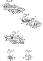
- the bifurcate member 29 is arranged for rotation from and back to a fastener-delivery position, shown in Figure 2, while passing an intermediate position, shown in Figure 3, in which the groove 33 extends transversely across the entire width of the guide channel 22.
- the groove 33 In the fastener-receiving position, the groove 33 extends obliquely to the magazine 19, and the mouth of the groove extends across the whole width of the guide channel 22, so that the first fastener 17a of the two fasteners 17a, 17b illustrated in Figure 2 is able to pass into the groove 33, the heads 18 of said fasteners being located above the section plane as indicated in broken lines.
- the bifurcate member 29 when located in the position illustrated in Figure 2, beneath the plane indicated by broken line 38 and extending parallel with the rotary axis and passing through the mouth of the groove in the bifurcate member and the fastener receiving and guiding means 15, when seen in the direction in which the rotary axis extends, the bifurcate member 29 has an outer contour which is located at a greater distance from the rotary axis than the outer contour of the tine or leg 31 located above said plane 38, such that when returning from the position illustrated in Figure 4 towards and to the position illustrated in Figure 2, the bifurcate member 29 displaces the fastener 17a shown in Figure 4 laterally into the fstener receiving and guiding means 15, said fastener adopting the same position as the fastener 17 illustrated in Figure 1.
- the plane 38 also forms the symmetry plane of the guide channel 22.
- the tine 31 of the bifurcate member has, as will best be seen from Figure 6, a length which so decreases from location 39 that the edge of the mouth of the bifurcate groove, at least in the positions of the bifurcate member 29 illustrated in Figures 2 and 3, forms an acute angle with the symmetry plane 38 of the guide channel 22. Further, when seen in the direction of the rotary axis, the groove 33 can extend obliquely away from the plane 37 ( Figure 3).
- the bifurcate member 29 substantially has the form of an excentrically journalled roller, and as will best be seen from Figures 2-4 for the purpose of rotating said member there is provided a reciprocatingly moveable rack 40 which is driven synchronously with the fastener-driving means 14.
- the rack is mounted on the outer end of a piston rod 41 connected to a piston 43 arranged in a cylinder 42.
- the cylinder 42 is carried by means 15.
- the rack 40 meshes with teeth arranged on the bifurcate member 29 along a circular-arcuate portion 44 curved about the rotary axis of said bifurcate member on the side of said member remote from the mouth of the groove 33.
- the toothed part 44 is located radially inwardly of the outer contour of the bifurcate member 29, when seen in the direction of the rotary axis.
- the reference 45 identifies a pipe for supplying compressed air to the cylinder 42, on the side of the piston 43 remote from the piston rod 41 wherewith the piston 43, together with the piston rod and the rack 40, is caused to move to the right, from the position shown in Figure 2 to the position shown in Figure 4, against the action of a return spring 46.
- the reference numeral 47 identifies a setting screw, for adjusting the length of stroke of the piston 43.
- a sealing ring 49 Arranged around the fastener-driving means 14, in the transition area between the main part 10 of the tool and the fastener receiving and guiding means 15 is a sealing ring 49.
- the pipe 48 is connected to the space located in the main part 10, beneath the piston 12 in Figure 1.
- the device according to the invention can also be used in conjunction with loose nails or other fasteners which do not have a pronounced head, in which case the guide channel 22 is provided with a bottom for supporting the fasteners axially, and also in conjunction, for example, with fasteners in the form of screws, in which case the fastener-driving means has the form of a screw-driver or the like and is arranged to rotate about a centre axis extending parallel with the fastener-driving direction.
- the requisite angle of slope of the mouth edge of the groove 33 relative to the plane 38, said edge camming the fasteners 17 into the groove 33, can also be produced by suitably angling the rotary axis 30 of the bifurcate member relative to the plane 38 and to the longitudinal direction of the magazine 19.
- the location at which the fasteners 17 first engage the edge of the mouth of the groove can be placed at the lower end of the groove or between the two ends of said groove, as seem in Figure 1.
Landscapes
- Engineering & Computer Science (AREA)
- Mechanical Engineering (AREA)
- Portable Nailing Machines And Staplers (AREA)
Abstract
Description
- The present invention relates to a fastener-driving device intended for such fasteners as nails, screws and the like, and comprising a fastener receiving and guiding means, for receiving fasteners in a position for co-action with a fastener-driving means and for guiding said fasteners towards the intended fastener-driving location; a fastener magazine having means for guiding fasteners arranged in side-by-side relationship towards said fastener receiving and guiding means; and feed means for feeding fasteners arriving from said magazine to said receiving and guiding means one at a time, said feed means including a bifurcate member which is arranged to co-act with a guide channel arranged to guide the fasteners transversely to their direction of movement during the passage of said fasteners between said magazine and said fastener receiving and guiding means, and which member is pivotally mounted on a shaft located adjacent the guide channel, said bifurcate member including a recess which is flanked by the tines or legs of said member and the width of which recess is adapted to receive one fastener at a time, said bifurcate member, for the purpose of feeding said fasteners one at a time, being reciprocatingly pivotable from a fastener-receiving position, in which the recess is directed obliquely towards the magazine and the mouth of said recess extends across at least substantially the whole width of the guide Ghannel, to and beyond a position in which the recess is directed obliquely towards said fastener receiving and guiding means and the mouth of said recess extends across at least substantially the whole width of the guide channel, via an intermediate position in which said recess extends transversely across the whole of said guide channel.
- The object of the present invention is to provide an improved device of the aforementioned kind which is able to operate with individual fasteners, i.e. fasteners which are not mounted on tape or fixed to each other in any way, without placing high, and therewith expensive, precision requirements on the fasteners as a result thereof.
- To this end, it is proposed in accordance with the invention that in a device of the kind described the recess has the form of an elongate slot or groove, the mouth-defining edges of which groove are formed by the outer ends of the tines or legs of the bifurcate member, of which mouth-defining edges the edge located nearest the magazine in the fastener-receiving position of the bifurcate member forms an acute angle with the plane of the guide channel. Such an arrangement minimizes the risk of the fasteners jamming between the guide-channel wall and the last-mentioned edge of the mouth of said groove, when the bifurcate member is pivoted from the fastener-receiving position while carrying a fastener, and obliquely arriving fasteners are effectively and, from an operational point of view, reliably aligned with and fed into the groove in said bifurcate member, through a camming action with said edge of the mouth of said groove.
- With the embodiments set forth in Claims 2 and 3, there is obtained favourable engagement between the bifurcate member and the fasteners within a functionally optimal region along the length of respective fasteners, while the fasteners, at the same time, are guided satisfactorily transversely to their direction of movement and are reliably supported to their longitudinal extension during passage between the magazine and the fastener receiving and guiding means.
- The embodiment of Claim 4 affords the further advantage where the fasteners are fed to the fastener receiving and guiding means in a positive and reliable manner, without requiring the provision of additional components.
- The embodiment according to Claim 5 enhances the operation reliability of the device, while Claim 6 defines a particularly advantageous means for driving the bifurcate member, said drive means being readily synchronized with the working movement of the fastener-driving means. The embodiment according to Claim 7 ensures trouble-free engagement between the bifurcate member and the fasteners, while the embodiment according to Claim 8 prevents the device malfunctioning as a result of air leaking along the fastener-driving means during its return stroke.
- So that the invention will be more readily understood and further features and advantages thereof made apparent, an exemplary embodiment of the invention will now be described with reference to the accompanying drawings, in which
- Figure 1 illustrates schematically, partly in side view and partly in section, a device according to the invention intended for driving fasteners in the form of loose nails, certain non-esential parts of the device having been omitted from the drawing, for the sake of clarity.
- Figures 2-4 are sectional views taken substantially on the line A-A in Figure 1, these views illustrating respectively the bifurcate member in its fastener-receiving position, its intermediate position and its fastener-delivering position, while feeding a fastener from the magazine to the fastener receiving and guiding means.
- Figure 5 illustrates the bifurcate member as seen in the direction of arrow B in Figure 3.
- Figure 6 illustrates the bifurcate member, as seen in the direction of arrow C in Figure 3.
- The fastener-driving device illustrated in Figure 1 includes a
main part 10, comprising acylinder 11 and a pneumatically operatedpiston 12 arranged within said cylinder. Thereference 13 identifies a trigger for starting each fastener-driving operation. For the sake of simplicity, lines, ports and valves for supplying compressed air to and for evacuating compressed air from the respective opposite sides of thepiston 12 have been omitted from Figure 1. Connected to thepiston 12 is apiston rod 14, which functions as a fastener-driving means, and which projects from one end of the cylinder. Connected to said one end of the cylinder is a substantially tubular fastener receiving and guidingmeans 15, which has a slot-like side opening 16 through which afastener 17 can be introduced laterally to the fastener-receiving position illustrated in Figure 1, in which position thefastener 17 is loosely held in readiness for co-action with the fastener-driving means 14, said fastener being held in said position by known means, not shown, such as magnets, withdrawable stop means etc. When compressed air if swiftly fed to the side of thepiston 12, incylinder 11, remote frommeans 14, the piston will move said means rapidly downwards, as seen in Figure 1, and the free end of themeans 14 will strike thehead 18 of thefastener 17 and push the fastener out of the receiving and guidingmeans 15, the free end of which should be directed towards the object into which thefastener 17 is to be driven, saidfastener 17 being guided in its outwardly going movement by themeans 15. - The
reference 19 identifies a partially illustrated magazine carried bymeans 15, for storing a multiplicity offasteners 17 arranged in side-by-side relationship and havingheads 18. Themagazine 19 includes tworails guide channel 22 and against theupper edges 23 of which theheads 18 rest. Thefasteners 17 are held in the guide channel of themagazine 19 by theleg 24 of a bar of L-shaped cross-section, saidleg 24 covering thechannel 22. As illustrated in Figure 1, the magazine can slope downwardly towards themeans 15, so as to permit thefasteners 17 to slide gravitationally towards said means. Alternatively, or in addition thereto, themagazine 19 may be provided, in the indicated manner, with aplunger 26 loaded by aspring 25, theplunger 26 urging the fasteners, arranged sequentially in themagazine 19, towards the fastener receiving and guidingmeans 15. - The
magazine 19 is joined to the fastener-receiving opening 16 of thefstener sidepieces rails magazine 19, said extension also being referenced 22. The feed means also includes abifurcate member 29, which is journalled, throughshafts 28, for rotation about an axis which is located adjacent theguide channel 22 and which extends substantially parallel to the direction in which the fasteners are driven into said object. As will best be seen from Figures 2-4, the bifurcate member includes a continuous slot orgroove 33 which is flanked by the legs ortines 31, 32 of said bifurcatedmember 29, and the width of which groove is adapted to receive fasteners, one at a time, at a location beneath theheads 18 of respective fasteners, and extends throughopenings sidepieces groove 33 in the direction ofshafts 30 is considerable, in relation to the length ofrespective fasteners 17, suitably at least 0.2-0.5 times the length of said fasteners. The edges of the mouth of thegroove 33 are formed by the outer end-edges of the forked tines orlegs 31 and 32 of the bifurcate member. As illustrated, theopenings sidepieces fasteners 17, by engaging the same beneathrespective heads 18 as the fasteners move from themagazine 19 to the fastener receiving and guidingmeans 15. - The
bifurcate member 29 is arranged for rotation from and back to a fastener-delivery position, shown in Figure 2, while passing an intermediate position, shown in Figure 3, in which thegroove 33 extends transversely across the entire width of theguide channel 22. In the fastener-receiving position, thegroove 33 extends obliquely to themagazine 19, and the mouth of the groove extends across the whole width of theguide channel 22, so that thefirst fastener 17a of the twofasteners groove 33, theheads 18 of said fasteners being located above the section plane as indicated in broken lines. When thebifurcate member 29 is rotated clockwise, thefastener 17a is moved beyond the intermediate position illustrated in Figure 3, to the fastener-delivering position, in which, as a result of mutual co-action between said fastener, theside 28 of the guide channel and the tine 31 of thebifurcate member 29, thefastener 17a is cammed out of the said groove when saidbifurcate member 29 is rotated somewhat. beyond the position in which thegroove 33 extends obliquely towards the fastener receiving and guidingmeans 15 and the mouth of said groove extends over the whole width of theguide channel 22. In order to prevent thebifurcate member 29 from pushing other fasteners located in themagazine 19, these fasteners being represented by thefastener 17b, backwards and forwards in theguide channel 22 as thebifurcate member 29 is rotated to and fro, that part of thebifurcate member 29 located in Figure 3 to the right of the plane which is indicated bybroken line 37 and which, when seen in the direction of the rotary axis of the bifurcate member, passes through the mouth of the groove and contains said rotary axis of said bifurcate member, has an outer contour which is curved substantially about said rotary axis in a circular-arcuate fashion. Further, when located in the position illustrated in Figure 2, beneath the plane indicated bybroken line 38 and extending parallel with the rotary axis and passing through the mouth of the groove in the bifurcate member and the fastener receiving and guidingmeans 15, when seen in the direction in which the rotary axis extends, thebifurcate member 29 has an outer contour which is located at a greater distance from the rotary axis than the outer contour of the tine or leg 31 located above saidplane 38, such that when returning from the position illustrated in Figure 4 towards and to the position illustrated in Figure 2, thebifurcate member 29 displaces thefastener 17a shown in Figure 4 laterally into the fstener receiving and guidingmeans 15, said fastener adopting the same position as thefastener 17 illustrated in Figure 1. Theplane 38 also forms the symmetry plane of theguide channel 22. - In order to avoid jamming of the
fasteners sidepiece 27, and also to optimize the receipt, transportation and delivery by the feed means of fasteners arriving from themagazine 19, the tine 31 of the bifurcate member has, as will best be seen from Figure 6, a length which so decreases from location 39 that the edge of the mouth of the bifurcate groove, at least in the positions of thebifurcate member 29 illustrated in Figures 2 and 3, forms an acute angle with thesymmetry plane 38 of theguide channel 22. Further, when seen in the direction of the rotary axis, thegroove 33 can extend obliquely away from the plane 37 (Figure 3). - As will be understood, the
bifurcate member 29 substantially has the form of an excentrically journalled roller, and as will best be seen from Figures 2-4 for the purpose of rotating said member there is provided a reciprocatinglymoveable rack 40 which is driven synchronously with the fastener-driving means 14. The rack is mounted on the outer end of apiston rod 41 connected to apiston 43 arranged in acylinder 42. Thecylinder 42 is carried bymeans 15. Therack 40 meshes with teeth arranged on thebifurcate member 29 along a circular-arcuate portion 44 curved about the rotary axis of said bifurcate member on the side of said member remote from the mouth of thegroove 33. Thetoothed part 44 is located radially inwardly of the outer contour of thebifurcate member 29, when seen in the direction of the rotary axis. Thereference 45 identifies a pipe for supplying compressed air to thecylinder 42, on the side of thepiston 43 remote from thepiston rod 41 wherewith thepiston 43, together with the piston rod and therack 40, is caused to move to the right, from the position shown in Figure 2 to the position shown in Figure 4, against the action of areturn spring 46. Thereference numeral 47 identifies a setting screw, for adjusting the length of stroke of thepiston 43. Arranged around the fastener-driving means 14, in the transition area between themain part 10 of the tool and the fastener receiving and guiding means 15 is asealing ring 49. Also provided is apipe 48 for conducting a stream of air directed towards the fastener receiving and guidingmeans 15 against afastener 17a delivered by the groove 33 (Figure 4) during the return stroke of the fastener-driving means 14 upwardly in Figure 1. To this end, thepipe 48 is connected to the space located in themain part 10, beneath thepiston 12 in Figure 1. - The invention is not restricted to the illustrated and described embodiment, but can naturally be modified in many ways within the inventive scope of the claims. The device according to the invention can also be used in conjunction with loose nails or other fasteners which do not have a pronounced head, in which case the
guide channel 22 is provided with a bottom for supporting the fasteners axially, and also in conjunction, for example, with fasteners in the form of screws, in which case the fastener-driving means has the form of a screw-driver or the like and is arranged to rotate about a centre axis extending parallel with the fastener-driving direction. The requisite angle of slope of the mouth edge of thegroove 33 relative to theplane 38, said edge camming thefasteners 17 into thegroove 33, can also be produced by suitably angling therotary axis 30 of the bifurcate member relative to theplane 38 and to the longitudinal direction of themagazine 19. The location at which thefasteners 17 first engage the edge of the mouth of the groove can be placed at the lower end of the groove or between the two ends of said groove, as seem in Figure 1.
Claims (8)
Priority Applications (1)
| Application Number | Priority Date | Filing Date | Title |
|---|---|---|---|
| AT83901428T ATE24141T1 (en) | 1982-04-28 | 1983-04-28 | FASTENER DRIVER FOR FASTENERS. |
Applications Claiming Priority (2)
| Application Number | Priority Date | Filing Date | Title |
|---|---|---|---|
| SE8202672A SE431417B (en) | 1982-04-28 | 1982-04-28 | DEVICE FOR RECOVERY OF FIXED ELEMENTS |
| SE8202672 | 1982-04-28 |
Publications (2)
| Publication Number | Publication Date |
|---|---|
| EP0120024A1 EP0120024A1 (en) | 1984-10-03 |
| EP0120024B1 true EP0120024B1 (en) | 1986-12-10 |
Family
ID=20346668
Family Applications (1)
| Application Number | Title | Priority Date | Filing Date |
|---|---|---|---|
| EP83901428A Expired EP0120024B1 (en) | 1982-04-28 | 1983-04-28 | A fastener-driving device |
Country Status (6)
| Country | Link |
|---|---|
| US (1) | US4593845A (en) |
| EP (1) | EP0120024B1 (en) |
| JP (1) | JPS59500659A (en) |
| DE (1) | DE3368222D1 (en) |
| SE (1) | SE431417B (en) |
| WO (1) | WO1983003790A1 (en) |
Families Citing this family (18)
| Publication number | Priority date | Publication date | Assignee | Title |
|---|---|---|---|---|
| US4598852A (en) * | 1982-04-06 | 1986-07-08 | Swingline Inc. | Fastener driving tool including fastener deformation and guidance arrangements |
| DE4211276C2 (en) | 1992-04-03 | 1997-08-28 | Profil Verbindungstechnik Gmbh | Holding device for holding, guiding and releasing a part to be joined, e.g. a mother |
| DE4447620C2 (en) * | 1994-06-10 | 2003-01-23 | Profil Verbindungstechnik Gmbh | Set=head for inserting fastening elements, e.g. bolts in pre=punched workpiece |
| US5558264A (en) * | 1995-02-13 | 1996-09-24 | Illinois Tool Works Inc. | Combustion-powered, fastener-driving tool with gas-actuated, fastener-feeding mechanism |
| US5904285A (en) * | 1997-11-26 | 1999-05-18 | Rayco Industries, Inc. | Nail transfer apparatus |
| EP1353780B1 (en) * | 2001-01-22 | 2008-08-20 | SFS intec Holding AG | Device for screwing in magazine-fed fastening elements |
| JP4570893B2 (en) * | 2004-03-31 | 2010-10-27 | 日本パワーファスニング株式会社 | Portable fastener driving tool |
| JP2005288608A (en) * | 2004-03-31 | 2005-10-20 | Jpf Works Kk | Portable fastener driving tool |
| US7225962B2 (en) | 2005-02-18 | 2007-06-05 | Illinois Tool Works Inc. | Nail advancement systems for nail arrays disposed within nailing tool magazines |
| US7571844B2 (en) * | 2006-01-26 | 2009-08-11 | Sigma Tool & Machine, A Partnership Between Sigma Tool & Machine Ltd. And Sigma Fasteners, Ltd. | Pneumatic hand tool for inserting t-nuts |
| US9999949B2 (en) * | 2007-09-14 | 2018-06-19 | Seagate Technology Llc | Work piece presentment |
| US9278798B2 (en) | 2012-09-14 | 2016-03-08 | Honda Motor Co., Ltd. | High speed bolt dispenser |
| US9299209B2 (en) | 2013-03-14 | 2016-03-29 | Honda Motor Co., Ltd. | Super high speed bolt delivery system |
| US9662777B2 (en) | 2013-08-22 | 2017-05-30 | Techtronic Power Tools Technology Limited | Pneumatic fastener driver |
| DE102013019518A1 (en) * | 2013-11-22 | 2015-06-11 | Tox Pressotechnik Gmbh & Co. Kg | "Device for attaching a joining element to a component section and tool" |
| DE102017100385A1 (en) * | 2017-01-10 | 2018-07-12 | Weber Schraubautomaten Gmbh | separation unit |
| US10286503B2 (en) * | 2017-06-23 | 2019-05-14 | Honda Motor Co., Ltd. | Fastener delivery system |
| JP7574409B2 (en) * | 2021-03-30 | 2024-10-28 | 新明和工業株式会社 | Rubber stopper supply device |
Family Cites Families (11)
| Publication number | Priority date | Publication date | Assignee | Title |
|---|---|---|---|---|
| US926412A (en) * | 1909-06-29 | Herman Hayssen | Nail feeding and driving device. | |
| US704467A (en) * | 1900-08-09 | 1902-07-08 | George Isreal Smith | Magazine nailing-hammer. |
| US1101659A (en) * | 1913-11-20 | 1914-06-30 | Herschel Ragsdale | Stapling-machine. |
| US2078660A (en) * | 1936-04-20 | 1937-04-27 | Stimpson Edwin B Co | Rivet setting machine |
| US2572012A (en) * | 1949-01-26 | 1951-10-23 | David G Robanske | Semiautomatic electric nailer |
| US2722248A (en) * | 1952-05-28 | 1955-11-01 | Graham Tie Dowel Service Compa | Dowel inserting device for tie pinning machines |
| US2855600A (en) * | 1954-05-04 | 1958-10-14 | United Shoe Machinery Corp | Automatic devices for inserting screws |
| DE1962146A1 (en) * | 1969-12-11 | 1971-07-01 | Sortimat Creuz & Co | Magazine device for electrical components |
| DE2148396A1 (en) * | 1971-09-28 | 1973-04-05 | Weber Schraubautomaten | INDEPENDENT SCREWING DEVICE |
| SU426819A1 (en) * | 1972-11-09 | 1974-05-05 | И. М. Акимов | CLIMBING EQUIPMENT |
| US4389012A (en) * | 1981-04-22 | 1983-06-21 | Duo-Fast Corporation | Fastener tool loading assembly |
-
1982
- 1982-04-28 SE SE8202672A patent/SE431417B/en not_active IP Right Cessation
-
1983
- 1983-04-28 JP JP58501529A patent/JPS59500659A/en active Pending
- 1983-04-28 US US06/571,545 patent/US4593845A/en not_active Expired - Fee Related
- 1983-04-28 EP EP83901428A patent/EP0120024B1/en not_active Expired
- 1983-04-28 WO PCT/SE1983/000170 patent/WO1983003790A1/en not_active Ceased
- 1983-04-28 DE DE8383901428T patent/DE3368222D1/en not_active Expired
Also Published As
| Publication number | Publication date |
|---|---|
| JPS59500659A (en) | 1984-04-19 |
| DE3368222D1 (en) | 1987-01-22 |
| SE431417B (en) | 1984-02-06 |
| SE8202672L (en) | 1983-10-29 |
| WO1983003790A1 (en) | 1983-11-10 |
| US4593845A (en) | 1986-06-10 |
| EP0120024A1 (en) | 1984-10-03 |
Similar Documents
| Publication | Publication Date | Title |
|---|---|---|
| US4593845A (en) | Oscillating separator for a fastener-driving device | |
| US6082577A (en) | Cable tie dispensing apparatus | |
| EP3065913B1 (en) | Fastener driving tool with an automatic nose chamber guide member | |
| US4463888A (en) | Fastener driving tool | |
| JP3538564B2 (en) | Attachment for continuous screw tightening | |
| US8302832B2 (en) | Fastener feeder delay for fastener driving tool | |
| US4485952A (en) | Shiftable magazine clip feed for fastener driving tools | |
| US20050001007A1 (en) | Pneumatic nailer | |
| CA2097859A1 (en) | Feeding device for an inserting tool for supplying fasteners, particularly screws | |
| US20030034377A1 (en) | Combustion tool with coil magazine | |
| US3247874A (en) | Power operated screw driver and feeding mechanism | |
| US4194665A (en) | Pneumatic stapler | |
| US3597142A (en) | Automatic nailing machine | |
| US11110574B2 (en) | Driving device and fastening element strip | |
| US2909780A (en) | Magazine construction | |
| US20030197046A1 (en) | Stapler with feed system for elements to be stapled to a workpiece | |
| JP4420163B2 (en) | Connecting nail supply mechanism for nailing machine | |
| JP3622199B2 (en) | Nail supply mechanism for nail nailing machine | |
| KR102957707B1 (en) | Screw supply device that allows reverse withdrawal of screw strips | |
| US2784406A (en) | Head construction for fastener driver | |
| US2982965A (en) | Fastener handling mechanisms | |
| JPH01117127A (en) | Constant feeder for fittings | |
| JPH028708Y2 (en) | ||
| JPS6320542Y2 (en) | ||
| JP2002154067A (en) | Connecting nail supply mechanism in nailing machine |
Legal Events
| Date | Code | Title | Description |
|---|---|---|---|
| PUAI | Public reference made under article 153(3) epc to a published international application that has entered the european phase |
Free format text: ORIGINAL CODE: 0009012 |
|
| 17P | Request for examination filed |
Effective date: 19840601 |
|
| AK | Designated contracting states |
Designated state(s): AT CH DE FR GB LI |
|
| GRAA | (expected) grant |
Free format text: ORIGINAL CODE: 0009210 |
|
| AK | Designated contracting states |
Kind code of ref document: B1 Designated state(s): AT CH DE FR GB LI |
|
| PG25 | Lapsed in a contracting state [announced via postgrant information from national office to epo] |
Ref country code: AT Effective date: 19861210 |
|
| REF | Corresponds to: |
Ref document number: 24141 Country of ref document: AT Date of ref document: 19861215 Kind code of ref document: T |
|
| REF | Corresponds to: |
Ref document number: 3368222 Country of ref document: DE Date of ref document: 19870122 |
|
| REG | Reference to a national code |
Ref country code: CH Ref legal event code: PUE Owner name: JONNY ANDERSSON |
|
| ET | Fr: translation filed | ||
| REG | Reference to a national code |
Ref country code: GB Ref legal event code: 732 |
|
| PLBE | No opposition filed within time limit |
Free format text: ORIGINAL CODE: 0009261 |
|
| STAA | Information on the status of an ep patent application or granted ep patent |
Free format text: STATUS: NO OPPOSITION FILED WITHIN TIME LIMIT |
|
| 26N | No opposition filed | ||
| PG25 | Lapsed in a contracting state [announced via postgrant information from national office to epo] |
Ref country code: GB Effective date: 19880428 |
|
| PG25 | Lapsed in a contracting state [announced via postgrant information from national office to epo] |
Ref country code: LI Effective date: 19880430 Ref country code: CH Effective date: 19880430 |
|
| GBPC | Gb: european patent ceased through non-payment of renewal fee | ||
| PG25 | Lapsed in a contracting state [announced via postgrant information from national office to epo] |
Ref country code: FR Free format text: LAPSE BECAUSE OF NON-PAYMENT OF DUE FEES Effective date: 19881229 |
|
| REG | Reference to a national code |
Ref country code: CH Ref legal event code: PL |
|
| PG25 | Lapsed in a contracting state [announced via postgrant information from national office to epo] |
Ref country code: DE Effective date: 19890103 |
|
| REG | Reference to a national code |
Ref country code: FR Ref legal event code: ST |