EP0118989B1 - Corona device - Google Patents
Corona device Download PDFInfo
- Publication number
- EP0118989B1 EP0118989B1 EP84300633A EP84300633A EP0118989B1 EP 0118989 B1 EP0118989 B1 EP 0118989B1 EP 84300633 A EP84300633 A EP 84300633A EP 84300633 A EP84300633 A EP 84300633A EP 0118989 B1 EP0118989 B1 EP 0118989B1
- Authority
- EP
- European Patent Office
- Prior art keywords
- electrodes
- support member
- corona
- biasing member
- wire
- Prior art date
- Legal status (The legal status is an assumption and is not a legal conclusion. Google has not performed a legal analysis and makes no representation as to the accuracy of the status listed.)
- Expired
Links
- 239000011521 glass Substances 0.000 claims abstract description 30
- 239000011888 foil Substances 0.000 abstract description 13
- WFKWXMTUELFFGS-UHFFFAOYSA-N tungsten Chemical compound [W] WFKWXMTUELFFGS-UHFFFAOYSA-N 0.000 description 8
- 229910001220 stainless steel Inorganic materials 0.000 description 6
- 150000002500 ions Chemical class 0.000 description 5
- 239000010935 stainless steel Substances 0.000 description 4
- 229910052721 tungsten Inorganic materials 0.000 description 4
- 239000010937 tungsten Substances 0.000 description 4
- 238000004519 manufacturing process Methods 0.000 description 3
- 108020003175 receptors Proteins 0.000 description 3
- 230000008901 benefit Effects 0.000 description 2
- 230000000694 effects Effects 0.000 description 2
- 239000003822 epoxy resin Substances 0.000 description 2
- 239000000463 material Substances 0.000 description 2
- 229920000515 polycarbonate Polymers 0.000 description 2
- 239000004417 polycarbonate Substances 0.000 description 2
- 229920000647 polyepoxide Polymers 0.000 description 2
- 229910001369 Brass Inorganic materials 0.000 description 1
- 239000004593 Epoxy Substances 0.000 description 1
- 239000000853 adhesive Substances 0.000 description 1
- 230000001070 adhesive effect Effects 0.000 description 1
- 239000010951 brass Substances 0.000 description 1
- 150000001875 compounds Chemical class 0.000 description 1
- 229920001940 conductive polymer Polymers 0.000 description 1
- 238000012423 maintenance Methods 0.000 description 1
- 239000002184 metal Substances 0.000 description 1
- 229910052751 metal Inorganic materials 0.000 description 1
- 230000001151 other effect Effects 0.000 description 1
- 108091008695 photoreceptors Proteins 0.000 description 1
- 230000000717 retained effect Effects 0.000 description 1
- 238000004544 sputter deposition Methods 0.000 description 1
Images

Classifications
-
- H—ELECTRICITY
- H01—ELECTRIC ELEMENTS
- H01T—SPARK GAPS; OVERVOLTAGE ARRESTERS USING SPARK GAPS; SPARKING PLUGS; CORONA DEVICES; GENERATING IONS TO BE INTRODUCED INTO NON-ENCLOSED GASES
- H01T19/00—Devices providing for corona discharge
-
- G—PHYSICS
- G03—PHOTOGRAPHY; CINEMATOGRAPHY; ANALOGOUS TECHNIQUES USING WAVES OTHER THAN OPTICAL WAVES; ELECTROGRAPHY; HOLOGRAPHY
- G03G—ELECTROGRAPHY; ELECTROPHOTOGRAPHY; MAGNETOGRAPHY
- G03G15/00—Apparatus for electrographic processes using a charge pattern
- G03G15/02—Apparatus for electrographic processes using a charge pattern for laying down a uniform charge, e.g. for sensitising; Corona discharge devices
- G03G15/0258—Apparatus for electrographic processes using a charge pattern for laying down a uniform charge, e.g. for sensitising; Corona discharge devices provided with means for the maintenance of the charging apparatus, e.g. cleaning devices, ozone removing devices G03G15/0225, G03G15/0291 takes precedence
-
- G—PHYSICS
- G03—PHOTOGRAPHY; CINEMATOGRAPHY; ANALOGOUS TECHNIQUES USING WAVES OTHER THAN OPTICAL WAVES; ELECTROGRAPHY; HOLOGRAPHY
- G03G—ELECTROGRAPHY; ELECTROPHOTOGRAPHY; MAGNETOGRAPHY
- G03G15/00—Apparatus for electrographic processes using a charge pattern
- G03G15/02—Apparatus for electrographic processes using a charge pattern for laying down a uniform charge, e.g. for sensitising; Corona discharge devices
- G03G15/0291—Apparatus for electrographic processes using a charge pattern for laying down a uniform charge, e.g. for sensitising; Corona discharge devices corona discharge devices, e.g. wires, pointed electrodes, means for cleaning the corona discharge device
Definitions
- the present invention relates to a corona device for use in modifying an electrostatic charge on dielectric surfaces, and more particularly to a corona erase device for use in an electrostatic printing apparatus to generate a supply of ions onto a rotating dielectric cylinder surface to cancel any charge remaining on the cylinder surface after a latent electrostatic image has been transferred from the cylinder surface to a copy medium.
- Corona devices are used both to place a uniform electrostatic charge on a dielectric surface and to eliminate an existing pattern of charge. Such actions are for the purposes of this description within the scope of the term "modifying an electrostatic charge on a dielectric surface".
- US-A-4,056,723 discloses a corona device for use with a dielectric surface to modify electrostatic charge on the surface, the device comprising an elongate dielectric support member, a plurality of straight corona electrodes mounted on the member in spaced relation about the member, each electrode having an electrically conductive core and electrically insulating sheath, an electrically conductive biasing member, means journalling' the support member for rotation and angular location at a number of positions equal to at leastthe number of electrodes, and electrical contact means for connecting the device to an electrical source, whereby upon rotating the support member into each of said selected positions electrical connection is made to a different one of the electrodes so that the user can select the electrodes to isolate damaged electrodes until all the electrodes have been used.
- a corona device as set out above is characterised by the biasing member encasing the support member and the electrodes on the support member, the contact means being coupled to the journalling means and establishing electrical connection to the biasing member and to a selected one of the electrodes.
- FIG. 1 shows somewhat schematically an exemplary electrostatic printer 30 incorporating the invention.
- This printer is illustrated primarily to demonstrate a suitable environment for the invention.
- Other printers and also photocopiers using photoreceptors could also benefit from the use of the invention.
- a cylinder 32 is mounted for rotation about an axis 34 and has an electrically conductive core 35 coated in a dielectric layer 36 capable of receiving an electrostatic image from a cartridge 38 driven by an electronic control system 40 and connected by mechanical connectors 42. As the cylinder rotates in the direction shown, an electrostatic image is formed by the cartridge 38 on the outer surface of the dielectric layer 36 and comes into contact with toner supplied from a hopper 44 by a feeder mechanism 46.
- the resulting toned image is carried by the cylinder 32 toward a nip formed with a pressure roller 48 having a compliant outer layer 49 positioned in a path of a receptor such as a paper 50 which enters between a pair of feed rollers 52, is driven by the cylinder 32 and roller 48, and leaves between a pair of output rollers 54.
- the pressure in the nip is sufficient to cause the toner to transfer to the receptor 50 and with sufficient pressure, the toner will be fused to the receptor.
- any toner remaining on the surface of the dielectric layer 36 is removed by a scraper blade assembly 56, and any residual electrostatic charge remaining on the surface is neutralized by a discharge head 58 positioned between the scraper blade assembly 56 and the cartridge 38.
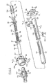
- FIG. 2 shows an exploded view of the components used in the corona erase assembly.
- a glass rod 60 is located in a brass guide tube 62 having a longitudinal aperture 63 and mounting blocks 64 and 66 are fitted over the ends 67, 68 of the tube respectively.
- a handle 70 sits in the mounting block 64 and its connection with the glass rod 60 as described in more detail later with reference to Fig. 3.
- the mounting blocks 64, 66 are adapted to be secured to opposite walls of the electrostatic printer by bolts which pass through respective slots 72, 74 in the mounting blocks.
- the end 68 of the glass rod 60 is centered in the guide tube 62 by a polycarbonate sleeve 76, which, as seen in Fig. 4, has a tapered end 78 with four longitudinal slots 80 spaced equally around its circumference to form fingers.
- the sleeve is a sliding fit in the guide tube and the diameter of the glass rod is slightly greater than that of the inner end of the sleeve 76 so that when the glass rod extends through the sleeve the fingers are deflected. Also, due to the resilience of the polycarbonate, reaction forces are created which cause the fingers to retain the glass tube 60 securely centered in the tube guide.
- the end 65 of the guide tube is located in a recess 61 in the mounting block 66 and is retained in this position by a screw 69.
- the guide tube 62 fits closely within an opening 71 in the block 64 and the inner end of the handle 70 projects into the guide tube to receive end 67 of the glass rod in a central cylindrical recess 82 as far as constriction 84.
- the handle 70 is located on the outside of the wall of the electrostatic printer and extends at least partly through the wall.
- the glass rod 60 has four straight corona electrodes 86 spaced equally around its circumference.
- Each electrode 86 comprises a tungsten wire 88 (Fig. 4a) which is sheathed in a high temperature glass 90 for most of the length of the tungsten wire.
- the glass is preferably type 1720 (trade mark) sold by Corning Glass.
- the wire 88 is 0.178 millimetres in diameter and the glass 90 is 0.0445 millimetres thick giving each electrode a diameter of 0.267 millimetres.
- the glass 90 is removed from each tungsten wire 88 to leave bare sections 92 (Fig. 4) which are then secured to the glass rod surface by a high temperature epoxy resin at two locations 94.
- a conductive biasing member in the form of a continuous wire 98 is wound around the glass rod 60 and over the electrodes for a portion of its length which is greater than the length of that part of the rotatable cylinder 32 (Fig. 1) used for printing.
- the wire 98 is made of tungsten and is 0.0508 millimetres in diameter.
- the wire 98 is wound closely to give 44 wraps to the cm along the rod to provide an effectively continuous conductive biasing member for all of the electrodes. It is important that the wire is wound uniformly to give a constant angle of helix between the wire 98 and the axis of the glass rod 60 over the length of the corona electrode.
- An electrically conductive foil 102 extends parallel to and between two of the electrodes beneath the wound wire 98 and is in contact with this wire at each wrap. The wire is terminated at each end by electrically insulating tapes 97, 99 wound around the glass rod 60.
- the conducting foil 102 is preferably made from 301 stainless steel and is 2.032 millimetres wide by 0.0254 millimetres thick. As seen in Fig. 4, the foil 102 has an end portion 104 which is wound around the glass rod so that it lies opposite to a small aperture 106 in the wall of the guide tube 62 for reasons to be explained later.
- the glass rod 60 is inserted through the sleeve 76 and the sleeve is then located within the guide tube 62 such that a rectangular aperture 108 in the insert is aligned with an aperture 110 in the wall of the tube 62.
- the tube, the insert and the glass rod are dimensioned such that when the glass rod is inserted and aligned, one of the bare sections 92 of one of the tungsten wires 88 is viewable through the now aligned apertures 108 and 110.
- This tungsten wire is contacted through these apertures by an electrical contact 112 housed in a moulded generally C-shaped contact block 114 (Fig.
- This contact provides for connecting the high voltage potential to the electrode 86 and is generally L-shaped and is secured by a high temperature epoxy resin, preferably Ecco-bond H 281 (trade mark) supplied by Emerson and Cum- ing, a Division of W. R. Grace and Co.
- the current path is completed by attaching a stainless steel brush contact 118 which is mounted on the tube 62 at the aperture 106 by two small screws 120.
- the brush contact 118 is made of wire 0.0508 millimetres diameter and contacts the wound wire 98 and the end portion 104 of the foil 102 thus completing the corona circuit.
- the end 67 of the glass rod is passed through the mounting block 64 and into the recess 82 of the handle 70 as previously described.
- shoulder 124 engages the outer face of the block 64 and that a central portion 125 is contained in the block.
- This portion defines an annular slot 127 joining four axial slots 126 spaced about the portion 125.
- These slots provide clearance for a locating screw 128 which retains the handle in the block 64 while permitting it to be rotated between four discrete positions by pulling it out until the screw is in the slot 127, turning it to align the screw with a new one of the slots 126 and pushing it in so that the screw prevents further rotation because it is now received in a slot 126.
- the glass rod must be positioned angularly relative to the handle and attached in this position so that on assembly in walls 111 (Figs.
- one electrode 86 is in the desired position and the others can be made to assume the same position by rotating the glass rod using the handle as described. This part of the assembly is of course quite critical.
- the glass rod is attached to the handle using any suitable high temperature adhesive such as the aforementioned Ecco-Bond H281.
- the transverse slots 72 and 74 in mounting blocks 64 and 66 permit the location of the mounting block to be adjusted relative to the cylinder 32 (Fig. 1) such that the corona electrode is located at the optimum distance from the surface of the cylinder. This distance is usually set by a feeler gauge and a typical distance between the electrode and the cylinder surface is 0.508 mm.
- the mounting block 64 also has a short annular recess 122 which receives a projection of an interlock with the handle on the printing apparatus used to engage and disengage contact between the cartridge 38 and the connector 42. The electrode cannot be changed unless this handle is moved to a disengaged position, and also, if the corona electrode assembly is not in the right position for use, the interlock projection will not engage.
- This leakage can result in offset voltages in the range +20 to -20 volts because the leakage is sensitive to the geometry, to the shape of the alternating wave form, and also to atmospheric conditions. If this atmospheric charge is not cancelled the printed copy can appear smudged or dirty due to toner being attracted to locations where no print is desired.
- the current path is altered as shown by the arrowed heavy line 140: the current then travels along the conductive biasing wire 98 until the break at point A and is then rerouted via the conductive foil 102 and then back onto the biasing wire 98 thereby providing electrical continuity.
- the small distance between adjacent wraps of the coil of the biasing wire 98 means that it is seen by the surface of the cylinder as the equivalent of a continuous member and the overall effect of these discrete wraps of the biasing member on the efficiency on erasure is negligible.
- the coil density was 44 wraps per cm. This was found to be the preferred value although in fact the density could be anywhere between 29-48 wraps percm for wire of 0.0508 millimetres (in this geometry).
- the power amplifier which drives the corona electrodes is a tuned power amplifier but is not highly selective. It operates with a nominal capacitance of 70 pF + 20 pF where the nominal capacitance is the equivalent capacitance of the full erase wire and screen as seen by the amplifier. When the coil density is less than 29 wraps per cm the spaces between wraps became excessive and if more than 48 wraps per cm is used, the wire effectively shields the electrode, leading to inefficient erasure.
- the conductive biasing wire could be of different thickness, for example 0.0254 millimetres and this has been found suitable with the coil density being modified. In this respect the diameter of the rod could also be changed.
- the electrode wire can also be of other materials provided that a good seal is achieved with the glass and that the wire and glass are matched for thermal expansion.
- Other glasses which have suitable mechanical and electrical properties include types 1723 and 7070 (trade marks) made by Corning Glass.
- the conductive biasing member 98 may also be stainless steel, however tungsten is preferred for its strength and high resistance to attack by sputtering and other effects of corona discharge.
- the foil 102 can also be a tungsten or stainless steel wire of 0.0254 millimetre diameter, although stainless steel foil is preferred because it provides a superior electrical contact with the wire brush, the other important requirement is that it is non- corroding.
- the corona energising signal may be between 1800-2200v peak-to-peak at a frequency of 75-150 KHz although the region 100-125 KHz is preferred, and the offset potential can vary between +20 and -20 volts, though with the materials and values given in the preferred embodiment -5 volts has been found to be the optimum value.
- the brush used to contact the conductive biasing member could be changed.
- the brush comprises a group of densely packed stands of stainless steel wire compressed between two pieces of metal which is then screwed into the side of the tube wall.
- any resilient contact such as a high voltage conductive polymer would achieve the same function.
- the L-shaped contact 112 is secured to the C-shaped block 114 by epoxy it could in fact be moulded in place.
- Advantages of the invention include ease of manufacture with a minimal amount of components which require no special manufacture.
- the life of each of the individual electrodes is maximized by compensating for breakage in the biasing electrode.
- the provisions of four electrodes with a common member maximizes the life of the corona erase device and also reduces the maintenance and replacement requirement in contrast to the existing devices.
Landscapes
- Physics & Mathematics (AREA)
- Engineering & Computer Science (AREA)
- Plasma & Fusion (AREA)
- General Physics & Mathematics (AREA)
- Electrostatic Charge, Transfer And Separation In Electrography (AREA)
- Elimination Of Static Electricity (AREA)
- Physical Or Chemical Processes And Apparatus (AREA)
- Plasma Technology (AREA)
Abstract
Description
- The present invention relates to a corona device for use in modifying an electrostatic charge on dielectric surfaces, and more particularly to a corona erase device for use in an electrostatic printing apparatus to generate a supply of ions onto a rotating dielectric cylinder surface to cancel any charge remaining on the cylinder surface after a latent electrostatic image has been transferred from the cylinder surface to a copy medium.
- Corona devices are used both to place a uniform electrostatic charge on a dielectric surface and to eliminate an existing pattern of charge. Such actions are for the purposes of this description within the scope of the term "modifying an electrostatic charge on a dielectric surface".
- The performance of a corona device is reduced by chemical compounds synthesized from the local air environment, which 'grow' on the surface of the electrode. Dielectric toner can also accumulate on the surface of the electrode which produces localised charging and this reduces the magnitude and the consistency of the corona current. These effects can substantially shorten the useful life of the corona electrode thereby requiring a relatively frequent replacement of the entire corona assembly. It is therefore desirable to provide an assembly having more than one corona wire to minimise down time and simplify replacement of a useless wire.
- One attempt to provide a multiple corona wire assembly is shown in US-A-4,056,723 which discloses a corona device for use with a dielectric surface to modify electrostatic charge on the surface, the device comprising an elongate dielectric support member, a plurality of straight corona electrodes mounted on the member in spaced relation about the member, each electrode having an electrically conductive core and electrically insulating sheath, an electrically conductive biasing member, means journalling' the support member for rotation and angular location at a number of positions equal to at leastthe number of electrodes, and electrical contact means for connecting the device to an electrical source, whereby upon rotating the support member into each of said selected positions electrical connection is made to a different one of the electrodes so that the user can select the electrodes to isolate damaged electrodes until all the electrodes have been used. If one of the electrodes should fail or become inefficient then the device can be manually or automatically moved to the next position. This assembly requires a considerable number of components and is quite complex resulting in relatively high manufacturing costs. In addition, should a conductive biasing member fail then the particular electrode associated with it can no longer be used even if it is still operating satisfactorily. Therefore, although this device solves some of the problems associated with single corona electrode devices it has serious limitations due to its cost, and doubtful reliability and efficiency.
- Accordingly it is an object of the present invention to provide an improved corona device having multiple corona wires.
- Thus, according to the invention, a corona device as set out above is characterised by the biasing member encasing the support member and the electrodes on the support member, the contact means being coupled to the journalling means and establishing electrical connection to the biasing member and to a selected one of the electrodes.
- The invention will be better understood with reference to the following description taken in combination with the accompanying drawings, in which:
- FIG.1 is a schematic side view, mostly in section, of an exemplary electrostatic printer in which a preferred embodiment of the corona device is mounted for use in erasing a pattern of charge on a dielectric cylinder;
- FIG. 2 is an exploded view of the corona erase device illustrating the components and how they are to be assembled;
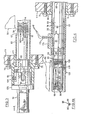
- FIG. 3 is a cross-sectional view taken on line 3-3 of Fig. 2 (drawn to a larger scale) and shows the cross-section of the corona device with the handle when assembled in the electrostatic printer;
- FIG. 4 is a view similar to Fig. 3 but taken on the line 4-4 of Fig. 2 at the opposite end of the corona device when assembled in the electrostatic printer; and
- FIG. 4a is a cross-section view on line 4a-4a of Fig. 4 of the corona electrode.
- Reference is made first to Fig. 1 which shows somewhat schematically an exemplary
electrostatic printer 30 incorporating the invention. This printer is illustrated primarily to demonstrate a suitable environment for the invention. Other printers and also photocopiers using photoreceptors could also benefit from the use of the invention. Acylinder 32 is mounted for rotation about anaxis 34 and has an electricallyconductive core 35 coated in adielectric layer 36 capable of receiving an electrostatic image from acartridge 38 driven by anelectronic control system 40 and connected bymechanical connectors 42. As the cylinder rotates in the direction shown, an electrostatic image is formed by thecartridge 38 on the outer surface of thedielectric layer 36 and comes into contact with toner supplied from ahopper 44 by afeeder mechanism 46. The resulting toned image is carried by thecylinder 32 toward a nip formed with apressure roller 48 having a compliantouter layer 49 positioned in a path of a receptor such as apaper 50 which enters between a pair offeed rollers 52, is driven by thecylinder 32 androller 48, and leaves between a pair ofoutput rollers 54. The pressure in the nip is sufficient to cause the toner to transfer to thereceptor 50 and with sufficient pressure, the toner will be fused to the receptor. - After passing through the nip between the
cylinder 32 and theroller 48, any toner remaining on the surface of thedielectric layer 36 is removed by ascraper blade assembly 56, and any residual electrostatic charge remaining on the surface is neutralized by adischarge head 58 positioned between thescraper blade assembly 56 and thecartridge 38. - Figure 2 shows an exploded view of the components used in the corona erase assembly. A
glass rod 60 is located in abrass guide tube 62 having alongitudinal aperture 63 andmounting blocks ends handle 70 sits in themounting block 64 and its connection with theglass rod 60 as described in more detail later with reference to Fig. 3. Themounting blocks respective slots - The
end 68 of theglass rod 60 is centered in theguide tube 62 by apolycarbonate sleeve 76, which, as seen in Fig. 4, has atapered end 78 with fourlongitudinal slots 80 spaced equally around its circumference to form fingers. The sleeve is a sliding fit in the guide tube and the diameter of the glass rod is slightly greater than that of the inner end of thesleeve 76 so that when the glass rod extends through the sleeve the fingers are deflected. Also, due to the resilience of the polycarbonate, reaction forces are created which cause the fingers to retain theglass tube 60 securely centered in the tube guide. - As seen in Fig. 2, when assembled, the
end 65 of the guide tube is located in arecess 61 in themounting block 66 and is retained in this position by ascrew 69. At its other end, and as seen in Fig. 3 theguide tube 62 fits closely within an opening 71 in theblock 64 and the inner end of thehandle 70 projects into the guide tube to receiveend 67 of the glass rod in a central cylindrical recess 82 as far asconstriction 84. - The
handle 70 is located on the outside of the wall of the electrostatic printer and extends at least partly through the wall. - Referring primarily to Fig. 2 the
glass rod 60 has fourstraight corona electrodes 86 spaced equally around its circumference. Eachelectrode 86 comprises a tungsten wire 88 (Fig. 4a) which is sheathed in ahigh temperature glass 90 for most of the length of the tungsten wire. The glass is preferably type 1720 (trade mark) sold by Corning Glass. - The
wire 88 is 0.178 millimetres in diameter and theglass 90 is 0.0445 millimetres thick giving each electrode a diameter of 0.267 millimetres. Near theend 68 of the glass rod theglass 90 is removed from eachtungsten wire 88 to leave bare sections 92 (Fig. 4) which are then secured to the glass rod surface by a high temperature epoxy resin at twolocations 94. - Referring now primarily to Figs. 3 and 4, a conductive biasing member in the form of a
continuous wire 98 is wound around theglass rod 60 and over the electrodes for a portion of its length which is greater than the length of that part of the rotatable cylinder 32 (Fig. 1) used for printing. Thewire 98 is made of tungsten and is 0.0508 millimetres in diameter. Thewire 98 is wound closely to give 44 wraps to the cm along the rod to provide an effectively continuous conductive biasing member for all of the electrodes. It is important that the wire is wound uniformly to give a constant angle of helix between thewire 98 and the axis of theglass rod 60 over the length of the corona electrode. This provides uniform ion clouds to pass through thelongitudinal aperture 63 which results in efficient erasure of charge on the surface of the cylinder. An electricallyconductive foil 102 extends parallel to and between two of the electrodes beneath thewound wire 98 and is in contact with this wire at each wrap. The wire is terminated at each end by electrically insulatingtapes glass rod 60. - The conducting
foil 102 is preferably made from 301 stainless steel and is 2.032 millimetres wide by 0.0254 millimetres thick. As seen in Fig. 4, thefoil 102 has anend portion 104 which is wound around the glass rod so that it lies opposite to asmall aperture 106 in the wall of theguide tube 62 for reasons to be explained later. - Reference is now made primarily to Fig. 2 to describe the assembly of the device. Firstly, the
glass rod 60 is inserted through thesleeve 76 and the sleeve is then located within theguide tube 62 such that arectangular aperture 108 in the insert is aligned with anaperture 110 in the wall of thetube 62. The tube, the insert and the glass rod are dimensioned such that when the glass rod is inserted and aligned, one of thebare sections 92 of one of thetungsten wires 88 is viewable through the now alignedapertures electrical contact 112 housed in a moulded generally C-shaped contact block 114 (Fig. 2) which is shaped to fit snugly on theguide tube 62. This contact provides for connecting the high voltage potential to theelectrode 86 and is generally L-shaped and is secured by a high temperature epoxy resin, preferably Ecco-bond H 281 (trade mark) supplied by Emerson and Cum- ing, a Division of W. R. Grace and Co. The current path is completed by attaching a stainlesssteel brush contact 118 which is mounted on thetube 62 at theaperture 106 by twosmall screws 120. Thebrush contact 118 is made of wire 0.0508 millimetres diameter and contacts thewound wire 98 and theend portion 104 of thefoil 102 thus completing the corona circuit. Next, theend 67 of the glass rod is passed through themounting block 64 and into the recess 82 of thehandle 70 as previously described. - When the handle is assembled it will be seen that
shoulder 124 engages the outer face of theblock 64 and that acentral portion 125 is contained in the block. This portion defines anannular slot 127 joining fouraxial slots 126 spaced about theportion 125. These slots provide clearance for a locatingscrew 128 which retains the handle in theblock 64 while permitting it to be rotated between four discrete positions by pulling it out until the screw is in theslot 127, turning it to align the screw with a new one of theslots 126 and pushing it in so that the screw prevents further rotation because it is now received in aslot 126. Evidently, during assembly, the glass rod must be positioned angularly relative to the handle and attached in this position so that on assembly in walls 111 (Figs. 3 and 4) oneelectrode 86 is in the desired position and the others can be made to assume the same position by rotating the glass rod using the handle as described. This part of the assembly is of course quite critical. The glass rod is attached to the handle using any suitable high temperature adhesive such as the aforementioned Ecco-Bond H281. - It should also be noted that the
transverse slots blocks block 64 also has a shortannular recess 122 which receives a projection of an interlock with the handle on the printing apparatus used to engage and disengage contact between thecartridge 38 and theconnector 42. The electrode cannot be changed unless this handle is moved to a disengaged position, and also, if the corona electrode assembly is not in the right position for use, the interlock projection will not engage. - When the electrostatic printer is in use current is supplied via the
contact 112 to energize theelectrode 86 to a potential of 2000v peak-to-peak using an a.c. signal of 125 KHz. A cloud of charged ions is produced along the length of the wire with the conductive biasingmember 98 and this cloud is delivered to the cylinder surface through thelongitudinal aperture 63 due to the potential difference across the gap. The current return is made via theconductive biasing wire 98 andportion 104 offoil 102 which contact thebrush contact 118. This foil ensures continuity even if for some reason thewire 98 should develop an electrical discontinuity. Thebiasing wire 98 andfoil 102 are kept at an offset potential of about -5 volts to compensate for leakage of ions through the screen. This leakage can result in offset voltages in the range +20 to -20 volts because the leakage is sensitive to the geometry, to the shape of the alternating wave form, and also to atmospheric conditions. If this atmospheric charge is not cancelled the printed copy can appear smudged or dirty due to toner being attracted to locations where no print is desired. - Any residual field on the dielectric surface is cancelled because a pool of positive and negative ions is created in the spaces between the electrode and the biasing wire. These electrons are effectively available to be attracted to charge on the dielectric to cancel the residual charge. No current will flow when the biasing wire is maintained at a voltage equal to the offset voltage and this condition will arise when the voltage on the dielectric is zero. The residual charge is then eliminated. Should the
conductive biasing wire 98 fail for any reason such as a break occurring for example at point A in Fig. 3, then the current path is altered as shown by the arrowed heavy line 140: the current then travels along theconductive biasing wire 98 until the break at point A and is then rerouted via theconductive foil 102 and then back onto thebiasing wire 98 thereby providing electrical continuity. The small distance between adjacent wraps of the coil of thebiasing wire 98 means that it is seen by the surface of the cylinder as the equivalent of a continuous member and the overall effect of these discrete wraps of the biasing member on the efficiency on erasure is negligible. - It will be appreciated that various changes may be made to the components of the apparatus hereinbefore described without departing from the scope of the invention as claimed.
- In the geometry of this the preferred embodiment, the coil density was 44 wraps per cm. This was found to be the preferred value although in fact the density could be anywhere between 29-48 wraps percm for wire of 0.0508 millimetres (in this geometry). The power amplifier which drives the corona electrodes is a tuned power amplifier but is not highly selective. It operates with a nominal capacitance of 70 pF + 20 pF where the nominal capacitance is the equivalent capacitance of the full erase wire and screen as seen by the amplifier. When the coil density is less than 29 wraps per cm the spaces between wraps became excessive and if more than 48 wraps per cm is used, the wire effectively shields the electrode, leading to inefficient erasure.
- The conductive biasing wire could be of different thickness, for example 0.0254 millimetres and this has been found suitable with the coil density being modified. In this respect the diameter of the rod could also be changed.
- The electrode wire can also be of other materials provided that a good seal is achieved with the glass and that the wire and glass are matched for thermal expansion. Other glasses which have suitable mechanical and electrical properties include types 1723 and 7070 (trade marks) made by Corning Glass.
- The
conductive biasing member 98 may also be stainless steel, however tungsten is preferred for its strength and high resistance to attack by sputtering and other effects of corona discharge. Thefoil 102 can also be a tungsten or stainless steel wire of 0.0254 millimetre diameter, although stainless steel foil is preferred because it provides a superior electrical contact with the wire brush, the other important requirement is that it is non- corroding. - The corona energising signal may be between 1800-2200v peak-to-peak at a frequency of 75-150 KHz although the region 100-125 KHz is preferred, and the offset potential can vary between +20 and -20 volts, though with the materials and values given in the preferred embodiment -5 volts has been found to be the optimum value.
- The brush used to contact the conductive biasing member could be changed. At present the brush comprises a group of densely packed stands of stainless steel wire compressed between two pieces of metal which is then screwed into the side of the tube wall. However, any resilient contact such as a high voltage conductive polymer would achieve the same function. In addition, although the L-shaped
contact 112 is secured to the C-shapedblock 114 by epoxy it could in fact be moulded in place. - Advantages of the invention include ease of manufacture with a minimal amount of components which require no special manufacture. The life of each of the individual electrodes is maximized by compensating for breakage in the biasing electrode. The provisions of four electrodes with a common member maximizes the life of the corona erase device and also reduces the maintenance and replacement requirement in contrast to the existing devices.
Claims (8)
Priority Applications (1)
| Application Number | Priority Date | Filing Date | Title |
|---|---|---|---|
| AT84300633T ATE29930T1 (en) | 1983-02-01 | 1984-02-01 | CORONA DEVICE. |
Applications Claiming Priority (2)
| Application Number | Priority Date | Filing Date | Title |
|---|---|---|---|
| CA420655 | 1983-02-01 | ||
| CA000420655A CA1190593A (en) | 1983-02-01 | 1983-02-01 | Corona device |
Publications (2)
| Publication Number | Publication Date |
|---|---|
| EP0118989A1 EP0118989A1 (en) | 1984-09-19 |
| EP0118989B1 true EP0118989B1 (en) | 1987-09-23 |
Family
ID=4124467
Family Applications (1)
| Application Number | Title | Priority Date | Filing Date |
|---|---|---|---|
| EP84300633A Expired EP0118989B1 (en) | 1983-02-01 | 1984-02-01 | Corona device |
Country Status (6)
| Country | Link |
|---|---|
| US (1) | US4514781A (en) |
| EP (1) | EP0118989B1 (en) |
| JP (1) | JPH061397B2 (en) |
| AT (1) | ATE29930T1 (en) |
| CA (1) | CA1190593A (en) |
| DE (1) | DE3466442D1 (en) |
Families Citing this family (19)
| Publication number | Priority date | Publication date | Assignee | Title |
|---|---|---|---|---|
| JPH0322758Y2 (en) * | 1985-07-22 | 1991-05-17 | ||
| JPH0762781B2 (en) * | 1985-09-24 | 1995-07-05 | オリンパス光学工業株式会社 | Static eliminator |
| JPS6258463U (en) * | 1985-10-01 | 1987-04-11 | ||
| DE3641169A1 (en) * | 1986-12-02 | 1988-06-09 | Hoechst Ag | ROLLER ELECTRODE AND DEVICE FOR TREATING THE SURFACE OF FILM COATINGS BY MEANS OF ELECTRIC CORONA DISCHARGE |
| US5319481A (en) * | 1986-12-23 | 1994-06-07 | Raychem Corporation | Encapsulated liquid crystal optical read/write storage medium and system |
| CH685004A5 (en) * | 1992-04-21 | 1995-02-28 | Sutter Apparatebau Ag Jurmin V | Dielectric-sheathing for electrodes of corona treatment plants. |
| US6148724A (en) * | 1994-12-20 | 2000-11-21 | Moore Business Forms, Inc. | Selective flexographic printing |
| US6278470B1 (en) | 1998-12-21 | 2001-08-21 | Moore U.S.A. Inc. | Energy efficient RF generator for driving an electron beam print cartridge to print a moving substrate |
| US6923979B2 (en) * | 1999-04-27 | 2005-08-02 | Microdose Technologies, Inc. | Method for depositing particles onto a substrate using an alternating electric field |
| US6428809B1 (en) | 1999-08-18 | 2002-08-06 | Microdose Technologies, Inc. | Metering and packaging of controlled release medication |
| US6366753B1 (en) | 1999-11-11 | 2002-04-02 | Heidelberger Druckmaschinen Ag | Charger wire tensioning mounting mechanism and method of using |
| US6298204B1 (en) | 1999-11-11 | 2001-10-02 | Nexpress Solutions Llc | Corona Charger with integral latch member for locating the charger relative to a roller |
| US6900436B1 (en) | 2000-10-14 | 2005-05-31 | Eastman Kodak Company | Corona wire tensioning mechanism |
| US20070087048A1 (en) * | 2001-05-31 | 2007-04-19 | Abrams Andrew L | Oral dosage combination pharmaceutical packaging |
| US6624413B1 (en) | 2002-11-12 | 2003-09-23 | Qc Electronics, Inc. | Corona treatment apparatus with segmented electrode |
| US20090087483A1 (en) * | 2007-09-27 | 2009-04-02 | Sison Raymundo A | Oral dosage combination pharmaceutical packaging |
| US8439033B2 (en) * | 2007-10-09 | 2013-05-14 | Microdose Therapeutx, Inc. | Inhalation device |
| EA018177B1 (en) * | 2007-11-07 | 2013-06-28 | Альфред Допплер | Impression cylinder |
| CN102665807A (en) | 2010-01-05 | 2012-09-12 | 微剂量治疗技术公司 | Inhalation device and method |
Family Cites Families (3)
| Publication number | Priority date | Publication date | Assignee | Title |
|---|---|---|---|---|
| GB1407718A (en) * | 1973-09-28 | 1975-09-24 | Rank Xerox Ltd | Electrical discharge devices |
| US3958162A (en) * | 1975-01-17 | 1976-05-18 | Coulter Information Systems, Inc. | Method and apparatus for charging an electrophotographic member |
| US4056723A (en) * | 1976-01-23 | 1977-11-01 | Xerox Corporation | Rotatable corona device |
-
1983
- 1983-02-01 CA CA000420655A patent/CA1190593A/en not_active Expired
- 1983-06-10 US US06/503,007 patent/US4514781A/en not_active Expired - Lifetime
-
1984
- 1984-02-01 DE DE8484300633T patent/DE3466442D1/en not_active Expired
- 1984-02-01 AT AT84300633T patent/ATE29930T1/en not_active IP Right Cessation
- 1984-02-01 JP JP59015301A patent/JPH061397B2/en not_active Expired - Lifetime
- 1984-02-01 EP EP84300633A patent/EP0118989B1/en not_active Expired
Also Published As
| Publication number | Publication date |
|---|---|
| US4514781A (en) | 1985-04-30 |
| EP0118989A1 (en) | 1984-09-19 |
| CA1190593A (en) | 1985-07-16 |
| JPH061397B2 (en) | 1994-01-05 |
| JPS606963A (en) | 1985-01-14 |
| ATE29930T1 (en) | 1987-10-15 |
| DE3466442D1 (en) | 1987-10-29 |
Similar Documents
| Publication | Publication Date | Title |
|---|---|---|
| US4514781A (en) | Corona device | |
| US4086650A (en) | Corona charging device | |
| CN101266433B (en) | Discharger, image carrier unit, and image forming apparatus | |
| US6064841A (en) | Power supply for a charging apparatus having a contact charger for charging an object to be charged | |
| EP0336028B1 (en) | Heat roll for electrophotography | |
| US5367366A (en) | Corona charger for image forming apparatus providing uniform surface charge of a recording medium | |
| CN101364711B (en) | Ion generating element, manufacturing method thereof, charging device, image forming device | |
| EP0026653B1 (en) | Corona generating device | |
| EP1126330B1 (en) | Process cartridge and image forming apparatus | |
| EP0507055B1 (en) | Image forming apparatus | |
| US5272505A (en) | Charging device, process unit having same and image forming apparatus using process unit | |
| US4056723A (en) | Rotatable corona device | |
| US4734722A (en) | Ion generator structure | |
| EP0181725A1 (en) | Corona charging device | |
| JP2002055508A (en) | Charging member, image forming apparatus and image forming method using the same | |
| EP0759583B1 (en) | Cleaning apparatus | |
| CN102540807B (en) | Charging member and image forming apparatus | |
| US3976880A (en) | Corona stabilization arrangement | |
| US5083145A (en) | Non-arcing blade printer | |
| US5293200A (en) | Electrostatic device for charging a photosensitive surface | |
| EP0496399A2 (en) | Charging device disposed close to member to be charged and image forming apparatus using same | |
| US5724636A (en) | Method and apparatus for transferring a toner image to a receiver sheet using an electrical bias | |
| AU728598B2 (en) | Charging device for charging charged body in non-contact state | |
| EP0274894A1 (en) | Corona charging device | |
| JPH1010842A (en) | A device that charges the film inside the drum |
Legal Events
| Date | Code | Title | Description |
|---|---|---|---|
| PUAI | Public reference made under article 153(3) epc to a published international application that has entered the european phase |
Free format text: ORIGINAL CODE: 0009012 |
|
| AK | Designated contracting states |
Kind code of ref document: A1 Designated state(s): AT BE CH DE FR GB IT LI LU NL SE |
|
| 17P | Request for examination filed |
Effective date: 19850311 |
|
| 17Q | First examination report despatched |
Effective date: 19860408 |
|
| GRAA | (expected) grant |
Free format text: ORIGINAL CODE: 0009210 |
|
| RAP1 | Party data changed (applicant data changed or rights of an application transferred) |
Owner name: DS HOLDINGS, INC. DMC DEVELOPMENT CORPORATION ZI |
|
| AK | Designated contracting states |
Kind code of ref document: B1 Designated state(s): AT BE CH DE FR GB IT LI LU NL SE |
|
| PG25 | Lapsed in a contracting state [announced via postgrant information from national office to epo] |
Ref country code: NL Effective date: 19870923 Ref country code: LI Effective date: 19870923 Ref country code: CH Effective date: 19870923 Ref country code: BE Effective date: 19870923 Ref country code: AT Effective date: 19870923 |
|
| REF | Corresponds to: |
Ref document number: 29930 Country of ref document: AT Date of ref document: 19871015 Kind code of ref document: T |
|
| PG25 | Lapsed in a contracting state [announced via postgrant information from national office to epo] |
Ref country code: SE Effective date: 19870930 |
|
| ET | Fr: translation filed | ||
| REF | Corresponds to: |
Ref document number: 3466442 Country of ref document: DE Date of ref document: 19871029 |
|
| ITF | It: translation for a ep patent filed | ||
| REG | Reference to a national code |
Ref country code: CH Ref legal event code: PL |
|
| NLV1 | Nl: lapsed or annulled due to failure to fulfill the requirements of art. 29p and 29m of the patents act | ||
| PG25 | Lapsed in a contracting state [announced via postgrant information from national office to epo] |
Ref country code: LU Free format text: LAPSE BECAUSE OF NON-PAYMENT OF DUE FEES Effective date: 19880229 |
|
| PLBE | No opposition filed within time limit |
Free format text: ORIGINAL CODE: 0009261 |
|
| STAA | Information on the status of an ep patent application or granted ep patent |
Free format text: STATUS: NO OPPOSITION FILED WITHIN TIME LIMIT |
|
| 26N | No opposition filed | ||
| ITTA | It: last paid annual fee | ||
| PGFP | Annual fee paid to national office [announced via postgrant information from national office to epo] |
Ref country code: DE Payment date: 19991231 Year of fee payment: 17 |
|
| PGFP | Annual fee paid to national office [announced via postgrant information from national office to epo] |
Ref country code: GB Payment date: 20000126 Year of fee payment: 17 |
|
| PGFP | Annual fee paid to national office [announced via postgrant information from national office to epo] |
Ref country code: FR Payment date: 20000210 Year of fee payment: 17 |
|
| PG25 | Lapsed in a contracting state [announced via postgrant information from national office to epo] |
Ref country code: GB Free format text: LAPSE BECAUSE OF NON-PAYMENT OF DUE FEES Effective date: 20010201 |
|
| GBPC | Gb: european patent ceased through non-payment of renewal fee |
Effective date: 20010201 |
|
| PG25 | Lapsed in a contracting state [announced via postgrant information from national office to epo] |
Ref country code: FR Free format text: LAPSE BECAUSE OF NON-PAYMENT OF DUE FEES Effective date: 20011031 |
|
| REG | Reference to a national code |
Ref country code: FR Ref legal event code: ST |
|
| PG25 | Lapsed in a contracting state [announced via postgrant information from national office to epo] |
Ref country code: DE Free format text: LAPSE BECAUSE OF NON-PAYMENT OF DUE FEES Effective date: 20011201 |