EP0117288B1 - Switch with arc-extinguishing means - Google Patents
Switch with arc-extinguishing means Download PDFInfo
- Publication number
- EP0117288B1 EP0117288B1 EP83111132A EP83111132A EP0117288B1 EP 0117288 B1 EP0117288 B1 EP 0117288B1 EP 83111132 A EP83111132 A EP 83111132A EP 83111132 A EP83111132 A EP 83111132A EP 0117288 B1 EP0117288 B1 EP 0117288B1
- Authority
- EP
- European Patent Office
- Prior art keywords
- arc
- plate
- arc extinguishing
- contact means
- fixed contact
- Prior art date
- Legal status (The legal status is an assumption and is not a legal conclusion. Google has not performed a legal analysis and makes no representation as to the accuracy of the status listed.)
- Expired
Links
Images





Classifications
-
- H—ELECTRICITY
- H01—ELECTRIC ELEMENTS
- H01H—ELECTRIC SWITCHES; RELAYS; SELECTORS; EMERGENCY PROTECTIVE DEVICES
- H01H9/00—Details of switching devices, not covered by groups H01H1/00 - H01H7/00
- H01H9/30—Means for extinguishing or preventing arc between current-carrying parts
- H01H9/34—Stationary parts for restricting or subdividing the arc, e.g. barrier plate
- H01H9/36—Metal parts
Definitions
- the present invention relates to a switch for making and breaking an electric current and more particularly to an arc-extinguishing mechanism thereof.
- the present invention is applicable mainly to electromagnetic contactors and no-fuse breakers.
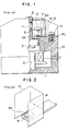
- Fig. 1 there is shown an example of a conventional electromagnetic contactor, having a symmetrical structure.
- the numeral 1 denotes a mounting base molded of a plastic material
- the numeral 2 denotes a fixed iron core which comprises laminated silicon steel plates on the mounting base 1
- the numeral 3 denotes a movable iron core which also comprises a lamination of silicon steel plates and is disposed in an opposed relation to the fixed iron core 2
- the numeral 4 denotes an operating coil which provides a driving force for attracting the movable iron core 3 toward the fixed iron core 2 against a tripping spring (not shown)
- the numeral 5 denotes a cross bar formed of a plastic material, the cross bar 5 having a square window and holding the movable iron core 3 at its lower end.
- the numeral 6 denotes a movable contact plate inserted through the square window of the cross bar 5 and held in place by a pressure spring 7;
- the numeral 6A denotes a movable contact affixed to the movable contact plate 6;
- the numeral 8 denotes a fixed contact plate for making an electric current, the fixed contact plate 8 being disposed in an opposed relation to the movable contact plate 6;
- the numeral 8A denotes a fixed contact affixed to the fixed contact plate 8;
- the numeral 8C denotes a terminal portion of the fixed contact plate 8.
- the numeral 9 denotes a terminal screw for connecting the electromagnetic contactor body to an external circuit
- the numeral 10 denotes a base for mounting the fixed.contact plate 8
- the numeral 11 denotes a cover which covers the upper portions of the electromagnetic contact plates.
- a metallic arc extinguishing plate 13 formed of a magnetic material for deflecting an arc 12 which is produced between the fixed contact 8A and movable contact 6A.
- Fig. 2 shows a mounting mode of the metallic arc extinguishing plate 13 relative to the fixed contact plate 8 and fixed contact 8A.
- the metallic arc extinguishing plate 13 is constituted as a channel-shaped plate erected so as to surround the fixed contact 8A, and it is provided with a notched end 14 in a position close to the fixed contact plate 8 for insertion therethrough of the latter.
- the movable iron core 3 moves away from the fixed iron core 2 by virtue of a tripping spring (not shown) when the operating coil 4 is deenergized. Since the cross bar 5 assumes the state shown in Fig. 1, at this time, the fixed and movable contacts 8A and 6A open producing the arc 12 between the fixed contact 8A and movable contact 6A. But the arc 12 is deflected by the metallic arc extinguishing plate 13 and extinguished at the zero point of electric current, so that the electric current is cut off.
- Fig. 3 shows a section of an arc extinguishing chamber.
- the arc 12 formed between the movable contact 6A and the fixed contact 8A is attracted by the metallic arc extinguishing plate 13 of a magnetic material and stretched like an arc 12A.
- the resultant increase in arc voltage causes insulation breakdown between the fixed contact plate 8 and the metallic arc extinguishing plate 13 and also between the notched end 14 of the metallic arc extinguishing plate 13 and the movable contact 6A.
- the arc 12A is divided into two arcs 12B and 12C, which arcs are extinguished at the zero point of electric current.
- the stretch of arc is restricted by the presence of the metallic arc extinguishing plate 13, and the arc voltage is low.
- insulation breakdown is difficult to take place between the fixed contact plate 8 and the metallic arc extinguishing plate 13 and also between the metallic arc extinguishing plate 13 and the movable contact 6A.
- the arc 12 is difficult to be divided into two arcs 12B and 12C.
- the arc 12 tends to stay due to a field concentration at the end portion 14 which is inferior in thermal conductivity.
- a field concentration at the end portion 14 which is inferior in thermal conductivity.
- EPC is disclosing a switch comprising fixed contact means, movable contact means adapted for movement to come into contact with said fixed contact means and to go out of contact with same such that the first gap is defined therebetween and an arc extinguishing grid of magnetic material, the plates forming said grid being disposed in a plane generally parallel to the direction of movement of the movable contact means.
- the fixed contact means are having a contact plate generally extending perpendicular to the plates forming the grid.
- An electrode is provided having a U-shaped bent portion disposed in proximity to said first contact means.
- the invention is concerned with a switch comprising fixed contact means, movable contact means adapted for movement to come into contact with said fixed contact means and go out of contact with the same such that a first gap is defined therebetween; and an arc extinguishing plate of magnetic material disposed in a plane generally parallel to the direction of movement of the movable contact means, said fixed contact means having a contact plate generally extending perpendicular to said arc extinguishing plate such that a second gap is defined therebetween.
- the invention is characterized by said arc extinguishing plate being provided with a tongue-like extension, said tongue-like extension having a U-shaped bent portion disposed in proximity of said fixed contact means and projecting towards the first gap or the second gap.
- the switch according to these embodiments include a fixed contact 8A; a movable contact 6A adapted for movement to come into contact with said fixed contact 8A and to go out of contact with the same such that a first gap is defined therebetween; an arc extinguishing plate 13 of magnetic metal provided generally in parallel with said movement.
- Said fixed contact 8A is affixed to said fixed contact plate 8 at an end portion thereof and said fixed contact plate 8 extends in a direction generally perpendicular to said arc extinguishing plate 13 to define a second gap therebetween.
- the switches of these embodiments are similar to the foregoing prior art construction. Therefore, only one metallic arc extinguishing plate 13 is shown in a perspective view in Fig. 4.
- the arc extinguishing plate of the invention differs from that of prior in that this metallic arc extinguishing plate 13 is provided with a U-shaped portion 13A, having a bent tongue-like extension at its notched end 14 in proximity to the fixed contact plate 8 and said U-shaped portion 13A, is positioned to project towards said first gap.
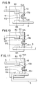
- Figs. 5 and 6 are longitudinally sectional views of an arc extinguishing chamber using this metallic arc extinguishing plate 13.
- the arc 12 is easily divided at the U-shaped portion 13A, of the metallic arc extinguishing plate 13 and then driven at a high speed on the metallic arc extinguishing plate 13 by a magnetic field build up by the electric current flowing in the U-shaped portion 13A of the arc extinguishing plate 13, so it is possible to extinguish the arc rapidly.
- a field concentration does not occur at the metallic arc extinguishing plate 13 nor is formed an arc at the fore end portion which is inferior in thermal conductivity, an extremely superior breaking performance can be attained.
- this metallic arc extinguishing plate 13 is provided with a U-shaped portion 13A, having a bent tongue-like extension at its notched end 14 which is provided in proximity to the fixed contact plate 8.
- a gas-flow hole 13B in the arc extinguishing plate 13 near the portion 13A.
- this metallic arc extinguishing plate 13 is different from the foregoing embodiment.
- Figs. 9 and 10 are longitudinally sectional views of an arc extinguishing chamber using this metallic arc extinguishing plate 13.
- the arc 12 produced between the fixed and movable contacts 8A and 6a is attracted by the metallic arc extinguishing plate 13 of a magnetic material, so that it is stretched along the U-shaped portion 13A, of the metallic arc deflecting plate 13 in the form of an arc 12E after assuming the state of an arc 12D.
- the arc voltage is raised and at the same time an arced gas which contains electrons and ionized anions passes through the gas-flow hole 13B, such that insulation breakdown occurs in the vicinity of the hole 13B, and immediately thereafter the arc 12E is divided into two arcs 12F and 12G.
- an electric current flows through the U-shaped portion 13A, of the metallic arc extinguishing plate 13, such that the divided arcs 12F and 12G are driven outwards in the form of arcs 12H and 121 shown in Fig. 10 by a magnetic field built up by the electric current flowing through the U-shaped portion 13A, of the metallic arc extinguishing plate 13, and arc extinguished at the zero point of the current.
- the current is cut off.
- the arc 12 in the electromagnetic contactor to which the present invention was applied causes insulation breakdown in the vicinity of the hole 13B which is formed in the arc extinguishing plate 13 above the U-shaped portion thereof and just thereafter the arc is divided in two and then driven at a high speed on the metallic arc extinguishing plate 13 by a magnetic field built up by the electric current flowing in the U-shaped portion of the arc extinguishing plate 13. In this way, it is possible to extinguish the arc rapidly.
- the presence of the gas-flow hole 13B is advantageous in that insulation breakdown takes place easily in the vicinity of the hole 13B and the arcing time is thereby shortened.
- FIG. 12 A still further embodiment of the invention will be described with reference to Figs. 12 to 13.
- Said embodiment has substantially the same structure as the first embodiment as seen in Fig. 12; this metallic arc extinguishing plate 13 is provided with a U-shaped portion 13A, having a bent tongue-like extension at its notched end 14 which is provided in proximity to the fixed contact plate 8.
- Said U-shaped portion 13A is oriented to project toward the first gap.
- the spacing d or the second gap between the U-shaped portion 13A, and the fixed contact plate 8 is set at approximately half the spacing D or said U-shaped portion 13A, is positioned midway in the first gap between the movable contact 6A and the fixed contact 8A when the former takes the opened position.
- This switch is suitable for use as a low- voltage switch for applied voltage below 660V, and in this case d is set at 1 to 3 mm for 2 to 6 mm of D.
- the spacing d between the U-shaped portion 13A, and the fixed contact plate 8 is set at approximately half the spacing D, a sufficient increase of the arc voltage is attainable and the arcing time is shortened by the rapid movement of the arc.
- the spacing d is set at approximately half the spacing D because it has been confirmed that a narrower spacing d will not raise the arc voltage whereas a wider spacing d makes it difficult for the arc between the contacts to move toward the metallic arc extinguishing plate 13.
- An arc extinguishing plate 13 includes a channel-shaped plate having a main portion 13A and wing portions 13C extending from respective sides thereof such that said channel-shaped plate surrounds the fixed contact 6A and the movable contact 8A.
- a fixed contact plate 8 extends in a direction perpendicular to said main portion 13A.
- the main portion 13A of the metallic arc extinguishing plate 13 is provided with a U-shaped portion 13A, having a bent tongue-like extension in a position close to the fixed contact plate 8.
- the width W2 of the projection 13A is almost equal to the width W1 between both sides 13C of the metallic arc extinguishing plate 13, and the gaps between the end portions of the U-shaped portions 13A, and the sides 13C of the arc-extinguishing plate 13 are extremely small.
- this metallic arc extinguishing plate 13 is different from the foregoing embodiments.
- FIG. 15A An arc extinguishing chamber using this metallic arc extinguishing plate 13 is shown in Fig. 15A.
- the arc 12 produced between the fixed and movable contacts 8A and 6A is attracted by the metallic arc extinguishing plate 13 of a magnetic material such that is stretched along the U-shaped portion 13A, as an arc 12E after assuming the state of the arc 12A.
- the arc voltage is raised whereas an arced gas 14 which contains electrons and ionized anions blows out from gaps 15 defined by the sides 13C of the arc extinguishing plate 13 and the end portions of the U-shaped portion 13A i as seen in Fig. 15B. Since the gaps 15 are small, however, the amount of the arced gas 14 is limited so much that the gas can be prevented from blowing out in a concentrated manner in the vicinity of the surface of the cover 11. Immediately thereafter, the arc 12B is divided into two arcs.
- an electric current flows through the U-shaped portion 13A 1 of the metallic arc extinguishing plate 13 such that said divided two arcs are driven outwards in the form of arcs 12H and 121 shown in Fig. 15A by a magnetic field built up by the electric current flowing through the U-shaped portion 13A, of the metallic arc extinguishing plate 13, and then are extinguished at the zero point of the current.
- the current is cut off.
- the metallic arc extinguishing plate 13 is provided with a U-shaped portion 13A i having a bent tongue-like extension at its notched end 14 which is provided in proximity to the fixed contact plate 8.
- the width W2 of the U-shaped portion 13A is almost equal to the width W1 of main portion 13A of the metallic arc extinguishing plate 13 which a gas-flow hole 13B is provided above the U-shaped portion 13A,.
- this metallic arc extinguishing plate 13 is different from the foregoing embodiments.
- An arc extinguishing chamber using this metallic arc extinguishing plate 13 is shown in Fig. 17A and 17B.
- the arc voltage is raised while an arced gas which contains electrons and ionized anions passes thorugh the gas-flow hole 13B such that there occurs insulation breakdown in the vicinity of the hole 13B, and immediately thereafter the arc 12E is divided into two arcs 12F and 12G.
- an electric current flows through the U-shaped portion 13A, of the metallic arc extinguishing plate 13 such that the divided arcs 12F and 12G are driven outwards in the form of arcs 12H and 121 shown in Fig. 9 by virtue of a magnetic field built up by the electric current flowing through the U-shaped portion 13A i of the metallic arc extinguishing plate, and are extinguished at the zero point of the current.
- the current is cut off.
- the extinction of arc is effected in the above-described manner.
- the arc 12 causes insulation breakdown in the vicinity of the hole 13B which is formed above the U-shaped portion 13A, of the metallic arc extinguishing plate 13.
- the arc is divided in two and then driven at a high speed on the metallic arc deflecting plate 13 by virtue of a magnetic field built up by the electric current flowing through the U-shaped portion 13A, thus extinguishing the arc rapidly.
- the presence of the hole 13B for flow of the arced gas permits an easy occurrence of insulation breakdown in the vicinity of the hole 13B, shortening the arcing time.
- the U-shaped portion 13A is formed such that its width W2 is substantially equal to the width W1 of the main portion 13A of the metallic arc extinguishing plate 13, the gaps between the U-shaped portion 13A, and both sides 13C of the metallic arc extinguishing plate 13 is negligible, whereby the efflux phenomenon of the high-temperature arced gas from the gaps is suppressed to a large extent and consequently an external interphase short-circuiting caused by a thermal deterioration of the cover 11 is prevented. This means an improvement of the motor inching life.
- a notch 16 is formed in the main portion 13A of the arc extinguishing plate 13.
- Said notch 16 is in the form of a slit formed positioned centrally of the main portion 13A and opening in facing relation to the fixed contact 8A.
- the arc produced at the time of opening of the contacts is attracted to the notch 16, effecting the rapid commutation of the arc to the arc extinguishing plate, whereby the arc can be extinguished in an instant. Consequently, it become possible to improve the arc cut-off performance of the device.
- the cut-off capability of the conventional device is of the order of only 500V, it has confirmed that the device of this embodiment can afford a cut-off capability of the order of 600V.
- the notch 16 is formed in a central position with respect to both side wall ends of the main portion 13A, the arc is converged to the central part of the main portion 13A. Consequently, the greater part of the arced gas is discharged from the notch 16, whereby the energy of the arced gas which passes between the base 10 and the side end of the arc box 11 is weakened, whereby the wear and damage of the base 11 and the side end portion of the arc box can be reduced.
- the general structure of said embodiment is substantially the same as that of the first embodiment.
- the arc extinguishing plate 13 has a U-shaped portion 13A, which has a tapering free end tongue 13A 2 .
- an auxiliary arc-extinguishing projection 13A3 is formed on the lower surface of the tongue portion of the arc extinguishing plate 13, whereby the arc extinguishing discharge between the arc extinguishing plate 13 and the fixed contact plate 8 can be done more easily.
- auxiliary arc-extinguishing projection 13A3 exhibits an auxiliary effect against the discharge wear, making the life of the arc extinguishing plate 13 longer.
- a gas-flow hole 13B is formed in a position above the U-shaped portion 13A, whereby the arc commutating time mentioned above can be further shortened. More particularly, an arced gas which contains electrons and ionized anions passes through the gas-flow hole 13B upon formation of an arc, such that insulation breakdown is apt to occur in the vicinity of the gas-flow hole 13B. As a result, it becomes possible to effect insulation breakdown between the movable contact 6A and the arc extinguishing plate 13, namely, the extremely quick commutation of the arc.
- the gas evolution phenomenon from the side of the arc box 11 can be eliminated.
- the side of the arc box 11, and that of the base 10 can be prevented from being eroded by the gas as experienced in the conventional device.
- This embodiment is different from the foregoing embodiment in that the fore end portion of the fixed contact plate 8 is bent in a channel-shaped form and the commutation of arc between the arc deflecting plate 13 and the fixed contact plate 8 is effected by the lower side of the U-shaped portion 13 and the fore end face of the fixed contact plate 8.
- the commutation behavior of the arc from the movable contact 6A to the arc extinguishing plate 13 in this embodiment is the same as in the previous embodiment. Therefore, also in this embodiment, like the previous embodiment, the arc produced between the contacts can be commutated to the arc extinguishing plate 13 and extinguished rapidly.
- a main portion 13A of the arc extinguishing plate 13 is bent outwards to form a U-shaped portion 13A, opposing the second gap which the arc deflecting plate 13 and the fixed contact plate 8 generally defines.
- the projecting end of the U-shaped portion 13A is opposed to the fixed contact plate 8 across the gap therebetween or projects toward the second gap.
- the shape of the U-shaped portion 13A is determined on the basis of results of a preliminary experiment conducted for determining the breaking capability for the arc which has been commutated from the movable contact 6A to the arc extinguishing plate 13.
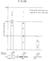
- Fig. 26 there are shown results of the experiment conducted using various shapes of electrodes and breaking currents corresponding to the shapes of the electrodes.
- a fuse was connected between electrodes of different shapes and a breaking current was let flow in the electrodes to open the fuse. Then the time required from the production of an arc between both electrodes upon failure of the fuse until completion of breaking was measured and the maximum breaking current in the case of the arc-extinguishing time being not longer than 0.5 cycle was determined.
- the current value capable of being interrupted is small, while when the electrodes have curved ends, the current breaking capability is enhanced.
- This current breaking capability is correlated with the arc-extinguishing capability. Consequently, the arc-extinguishing capability can be enhanced by forming the arc-extinguishing portion of the arc deflecting plate in a curved shape, whereby the arc which has been commutated to the arc extinguishing plate 13 can be extinguished rapidly.
- the arc-extinguishing portion of the arc extinguishing plate is formed in U-shaped on the basis of the foregoing experimental results.
- the fixed contact plate 8 is formed in the shape of a flat plate, and the U-shaped portion 13A, of the arc extinguishing plate 13, which is opposed to and spaced by a predetermined distance from the fixed contact plate 8, is formed as a U-shaped curved portion. Therefore, as will be appreciated from the foregoing experimental results, the arc-extinguishing capability is enhanced, whereby a rapid extinction of arc from the U-shaped portion 13 to the fixed contact plate 8 is attained.
- the arc which has been produced at the time of opening of the contacts and commutated to the arc extinguishing plate can be extinguished rapidly from the arc extinguishing plate to the fixed contact plate.
- the grid scarcely undergoes wear or damage at the time of an arc-extinguishing discharge from the arc extinguishing plate to the fixed contact plate, and consequently the life of the arc extinguishing plate can be prolonged.
- the arc extinguishing plate 13 in each embodiment is made of ferritic stainless steel plate (SUS 430).
- the ordinary arc extinguishing plates of iron are partially evaporated by the heat of the arc and discharged as an arced gas to the exterior. As a result, the arc extinguishing iron plates are eroded and become worn and damaged over a long period of use.
- the arc extinguishing plates will not undergo wear or damage even over a long period of use, thereby permitting prolongation of the service life thereof.
- the metallic arc extinguishing plate is provided with a U-shaped portion in a position close to the fixed contact plate.
Landscapes
- Arc-Extinguishing Devices That Are Switches (AREA)
Description
- The present invention relates to a switch for making and breaking an electric current and more particularly to an arc-extinguishing mechanism thereof.
- The present invention is applicable mainly to electromagnetic contactors and no-fuse breakers.
- Referring first to Fig. 1, there is shown an example of a conventional electromagnetic contactor, having a symmetrical structure. In Fig. 1, the
numeral 1 denotes a mounting base molded of a plastic material; thenumeral 2 denotes a fixed iron core which comprises laminated silicon steel plates on themounting base 1; the numeral 3 denotes a movable iron core which also comprises a lamination of silicon steel plates and is disposed in an opposed relation to thefixed iron core 2, thenumeral 4 denotes an operating coil which provides a driving force for attracting the movable iron core 3 toward the fixediron core 2 against a tripping spring (not shown); the numeral 5 denotes a cross bar formed of a plastic material, the cross bar 5 having a square window and holding the movable iron core 3 at its lower end. Thenumeral 6 denotes a movable contact plate inserted through the square window of the cross bar 5 and held in place by apressure spring 7; thenumeral 6A denotes a movable contact affixed to themovable contact plate 6; thenumeral 8 denotes a fixed contact plate for making an electric current, thefixed contact plate 8 being disposed in an opposed relation to themovable contact plate 6; thenumeral 8A denotes a fixed contact affixed to thefixed contact plate 8; and thenumeral 8C denotes a terminal portion of thefixed contact plate 8. - Further, the numeral 9 denotes a terminal screw for connecting the electromagnetic contactor body to an external circuit; the
numeral 10 denotes a base for mounting thefixed.contact plate 8; and thenumeral 11 denotes a cover which covers the upper portions of the electromagnetic contact plates. Inside thecover 11 is disposed a metallicarc extinguishing plate 13 formed of a magnetic material for deflecting anarc 12 which is produced between the fixedcontact 8A andmovable contact 6A. Fig. 2 shows a mounting mode of the metallicarc extinguishing plate 13 relative to thefixed contact plate 8 and fixedcontact 8A. The metallic arcextinguishing plate 13 is constituted as a channel-shaped plate erected so as to surround thefixed contact 8A, and it is provided with anotched end 14 in a position close to thefixed contact plate 8 for insertion therethrough of the latter. - In this conventional electromagnetic contactor having the above-described construction, the movable iron core 3 moves away from the fixed
iron core 2 by virtue of a tripping spring (not shown) when theoperating coil 4 is deenergized. Since the cross bar 5 assumes the state shown in Fig. 1, at this time, the fixed andmovable contacts arc 12 between the fixedcontact 8A andmovable contact 6A. But thearc 12 is deflected by the metallicarc extinguishing plate 13 and extinguished at the zero point of electric current, so that the electric current is cut off. - The extinguishing process for the
arc 12 in such conventional electromagnetic contactor will now be described more in detail with reference to Fig. 3 which shows a section of an arc extinguishing chamber. Thearc 12 formed between themovable contact 6A and the fixedcontact 8A is attracted by the metallic arcextinguishing plate 13 of a magnetic material and stretched like an arc 12A. The resultant increase in arc voltage causes insulation breakdown between thefixed contact plate 8 and the metallic arcextinguishing plate 13 and also between thenotched end 14 of the metallicarc extinguishing plate 13 and themovable contact 6A. As a result, the arc 12A is divided into twoarcs 12B and 12C, which arcs are extinguished at the zero point of electric current. In the conventional electromagnetic contactor wherein the arc is extinguished according to such process, the stretch of arc is restricted by the presence of the metallic arcextinguishing plate 13, and the arc voltage is low. As a result insulation breakdown is difficult to take place between thefixed contact plate 8 and the metallicarc extinguishing plate 13 and also between the metallic arcextinguishing plate 13 and themovable contact 6A. In other words, thearc 12 is difficult to be divided into twoarcs 12B and 12C. Moreover, once thearc 12 is divided into two, thearc 12 tends to stay due to a field concentration at theend portion 14 which is inferior in thermal conductivity. Thus, not only remarkable breaking performance cannot be attained but it creates a major factor of degradation of the arc extinguishing plate. - EP-A-0067 321 which falls under Article 54 (3) EPC is disclosing a switch comprising fixed contact means, movable contact means adapted for movement to come into contact with said fixed contact means and to go out of contact with same such that the first gap is defined therebetween and an arc extinguishing grid of magnetic material, the plates forming said grid being disposed in a plane generally parallel to the direction of movement of the movable contact means. The fixed contact means are having a contact plate generally extending perpendicular to the plates forming the grid. An electrode is provided having a U-shaped bent portion disposed in proximity to said first contact means.
- The invention is concerned with a switch comprising fixed contact means, movable contact means adapted for movement to come into contact with said fixed contact means and go out of contact with the same such that a first gap is defined therebetween; and an arc extinguishing plate of magnetic material disposed in a plane generally parallel to the direction of movement of the movable contact means, said fixed contact means having a contact plate generally extending perpendicular to said arc extinguishing plate such that a second gap is defined therebetween..
- It is an object of the invention to provide such a switch which shows an improved performance.
- The invention is characterized by said arc extinguishing plate being provided with a tongue-like extension, said tongue-like extension having a U-shaped bent portion disposed in proximity of said fixed contact means and projecting towards the first gap or the second gap.
- The invention now will be explained in more detail referring to the drawings Figures 4-28.
- Fig. 1 is a partially cross-sectional view of a conventional switch being employed in an electromagnetic contactor;
- Fig. 2 is a perspective diagram of an arc deflecting chamber of the electromagnetic contactor of Fig. 1, the essential part thereof being enlarged in the view;
- Fig. 3 is an illustration showing an arc extinguished process which is performed in the conventional electromagnetic contactor;
- Fig. 4 is a diagram in perspective showing an arc deflecting plate in one embodiment of the present invention;
- Figs. 5 and 6 are illustrations showing arc-extinguishing processes being performed in the embodiment of Fig. 4;
- Fig. 7 shows another embodiment of the invention and the arc-extinguishing process performed therein;
- Fig. 8 is a diagram in perspective showing an arc extinguishing plate of a further embodiment of the invention;
- Figs. 9 and 10 are illustrations showing arc-extinguishing processes being performed in the embodiment of Fig. 8;
- Fig. 11 shows a still further embodiment of the invention and the arc-extinguishing process performed therein;
- Fig. 12 is a diagram in perspective of a still further embodiment of the invention;
- Fig. 13 is a side view of the embodiment of Fig. 12 showing the arc-extinguishing process performed therein;
- Fig. 14 is a diagram in perspective of an arc extinguishing plate of a still further embodiment of the invention;
- Figs. 15A and 15B are illustrations showing the arced gas flowout taking place in the embodiment of Fig. 14;
- Fig. 16 is a diagram in perspective of the arc extinguishing plate of a still further embodiment of the invention;
- Figs. 17A and 17B are illustrations showing the arced gas flowout taking place in the embodiment of Fig. 16;
- Fig. 18 and Fig. 19 are illustrations showing arc-extinguishing processes in the above embodiment;
- Fig. 20 is a perspective view of the arc plate of a still further embodiment of the invention;
- Fig. 21 is a diagram in perspective of the arc extinguishing plate of a still further embodiment of the invention;
- Figs. 22 and 23 are illustration showing arc-extinguishing processes taking place in the switch according to the above embodiment;
- Fig. 24 is a side view of a still further embodiment of the invention;
- Fig. 25 is a diagram in perspective of the arc extinguishing plate of a still further embodiment of the invention;
- Fig. 26 is a graph showing the relationship between the electrode configuration and the cut off current obtained as a result of tests conducted to design the shape of the arc extinguishing plate; and
- Figs. 27 and 28 are illustrations showing arc-extinguishing processes taking place in the switch according to the embodiment of Fig. 25.
- The present invention will now be described with reference to embodiments thereof which are illustrated in Figs. 4 through 7. The switch according to these embodiments include a fixed
contact 8A; amovable contact 6A adapted for movement to come into contact with said fixedcontact 8A and to go out of contact with the same such that a first gap is defined therebetween; an arcextinguishing plate 13 of magnetic metal provided generally in parallel with said movement. Said fixedcontact 8A is affixed to saidfixed contact plate 8 at an end portion thereof and said fixedcontact plate 8 extends in a direction generally perpendicular to saidarc extinguishing plate 13 to define a second gap therebetween. Except a metallic arc extinguishing plate, the switches of these embodiments are similar to the foregoing prior art construction. Therefore, only one metallic arcextinguishing plate 13 is shown in a perspective view in Fig. 4. - As shown in Fig. 4, the arc extinguishing plate of the invention differs from that of prior in that this metallic arc
extinguishing plate 13 is provided with aU-shaped portion 13A, having a bent tongue-like extension at its notchedend 14 in proximity to the fixedcontact plate 8 and said U-shapedportion 13A, is positioned to project towards said first gap. - Figs. 5 and 6 are longitudinally sectional views of an arc extinguishing chamber using this metallic arc
extinguishing plate 13. - With reference to these figures, the process from the formation of the
arc 13 between the fixed andmovable contacts arc 12 formed between the fixed andmovable contacts extinguishing plate 13 of a magnetic material. As a result it is stretched curvedly along theU-shaped portion 13A of the metallicarc extinguishing plate 13 like anarc 12E after assuming the state of anarc 12D, thus increasing the arc voltage. Subsequently, insulation breakdown occurs between themovable contact 6A and theU-shaped portion 13A of the metallicarc extinguishing plate 13 and also between theU-shaped portion 13A of thearc extinguishing plate 13 and the fixedcontact plate 8 such that the arc is divided into twoarcs U-shaped portion 13A of the metallicarc extinguishing plate 13, so that the divided arcs 12F and 12G are more driven outwards in the form ofarcs U-shaped portion 13A of the metallicarc extinguishing plate 13, and are extinguished at the zero point of the current. Thus, the current is cut off. - In the electromagnetic contactor to which the present invention was applied, since the extinction of arc is effected in the above described manner, the
arc 12 is easily divided at theU-shaped portion 13A, of the metallicarc extinguishing plate 13 and then driven at a high speed on the metallicarc extinguishing plate 13 by a magnetic field build up by the electric current flowing in theU-shaped portion 13A of thearc extinguishing plate 13, so it is possible to extinguish the arc rapidly. Moreover, since unlike the conventional contactor shown in Fig. 3 a field concentration does not occur at the metallicarc extinguishing plate 13 nor is formed an arc at the fore end portion which is inferior in thermal conductivity, an extremely superior breaking performance can be attained. - It goes without saying that the present invention can afford the same effect also in the case of another embodiment using such a different shape of a fixed
contact plate 8 as shown in Fig. 7. - A further embodiment of the invention will be described referring to Figs. 8 to 11. As shown in Fig. 8, this metallic
arc extinguishing plate 13 is provided with aU-shaped portion 13A, having a bent tongue-like extension at its notchedend 14 which is provided in proximity to the fixedcontact plate 8. Although the above mentioned structure is substantially the same as the above mentioned embodiments, there are additionally provided a gas-flow hole 13B in thearc extinguishing plate 13 near theportion 13A. In this respect, this metallicarc extinguishing plate 13 is different from the foregoing embodiment. - Figs. 9 and 10 are longitudinally sectional views of an arc extinguishing chamber using this metallic
arc extinguishing plate 13. - With reference to these figures, the process from the production of the
arc 12 between the fixed andmovable contacts arc 12 produced between the fixed andmovable contacts 8A and 6a is attracted by the metallicarc extinguishing plate 13 of a magnetic material, so that it is stretched along theU-shaped portion 13A, of the metallicarc deflecting plate 13 in the form of anarc 12E after assuming the state of anarc 12D. At this time, the arc voltage is raised and at the same time an arced gas which contains electrons and ionized anions passes through the gas-flow hole 13B, such that insulation breakdown occurs in the vicinity of thehole 13B, and immediately thereafter thearc 12E is divided into twoarcs U-shaped portion 13A, of the metallicarc extinguishing plate 13, such that the divided arcs 12F and 12G are driven outwards in the form ofarcs U-shaped portion 13A, of the metallicarc extinguishing plate 13, and arc extinguished at the zero point of the current. Thus, the current is cut off. - Since extinction of arc is effected in the above-described manner, the
arc 12 in the electromagnetic contactor to which the present invention was applied causes insulation breakdown in the vicinity of thehole 13B which is formed in thearc extinguishing plate 13 above the U-shaped portion thereof and just thereafter the arc is divided in two and then driven at a high speed on the metallicarc extinguishing plate 13 by a magnetic field built up by the electric current flowing in the U-shaped portion of thearc extinguishing plate 13. In this way, it is possible to extinguish the arc rapidly. Moreover, since a field concentration does not occur at the metallicarc extinguishing plate 13 nor is produced an arc at the fore end portion which is inferior in thermal conductivity unlike the conventional contactor shown in Fig. 3, an extremely superior breaking performance can be attained. Particularly, the presence of the gas-flow hole 13B is advantageous in that insulation breakdown takes place easily in the vicinity of thehole 13B and the arcing time is thereby shortened. - It goes without saying that the present invention can afford the same effect also in the case of such a different shape of a fixed
contact plate 8 as shown in Fig. 11. - A still further embodiment of the invention will be described with reference to Figs. 12 to 13. Said embodiment has substantially the same structure as the first embodiment as seen in Fig. 12; this metallic
arc extinguishing plate 13 is provided with aU-shaped portion 13A, having a bent tongue-like extension at its notchedend 14 which is provided in proximity to the fixedcontact plate 8. SaidU-shaped portion 13A, is oriented to project toward the first gap. The spacing d or the second gap between theU-shaped portion 13A, and the fixedcontact plate 8 is set at approximately half the spacing D or saidU-shaped portion 13A, is positioned midway in the first gap between themovable contact 6A and the fixedcontact 8A when the former takes the opened position. This switch is suitable for use as a low- voltage switch for applied voltage below 660V, and in this case d is set at 1 to 3 mm for 2 to 6 mm of D. - Since the spacing d between the
U-shaped portion 13A, and the fixedcontact plate 8 is set at approximately half the spacing D, a sufficient increase of the arc voltage is attainable and the arcing time is shortened by the rapid movement of the arc. - The spacing d is set at approximately half the spacing D because it has been confirmed that a narrower spacing d will not raise the arc voltage whereas a wider spacing d makes it difficult for the arc between the contacts to move toward the metallic
arc extinguishing plate 13. - A still further embodiment will be described with reference to Figs. 14, 15A, and 15B. An
arc extinguishing plate 13 includes a channel-shaped plate having amain portion 13A andwing portions 13C extending from respective sides thereof such that said channel-shaped plate surrounds the fixedcontact 6A and themovable contact 8A. A fixedcontact plate 8 extends in a direction perpendicular to saidmain portion 13A. - As shown in Fig. 14, the
main portion 13A of the metallicarc extinguishing plate 13 is provided with aU-shaped portion 13A, having a bent tongue-like extension in a position close to the fixedcontact plate 8. The width W2 of theprojection 13A is almost equal to the width W1 between bothsides 13C of the metallicarc extinguishing plate 13, and the gaps between the end portions of theU-shaped portions 13A, and thesides 13C of the arc-extinguishingplate 13 are extremely small. In this respect, this metallicarc extinguishing plate 13 is different from the foregoing embodiments. - An arc extinguishing chamber using this metallic
arc extinguishing plate 13 is shown in Fig. 15A. With reference to this figure, the process from the production of thearc 12 between the fixed andmovable contacts arc 12 produced between the fixed andmovable contacts arc extinguishing plate 13 of a magnetic material such that is stretched along theU-shaped portion 13A, as anarc 12E after assuming the state of the arc 12A. At this time, the arc voltage is raised whereas an arcedgas 14 which contains electrons and ionized anions blows out fromgaps 15 defined by thesides 13C of thearc extinguishing plate 13 and the end portions of theU-shaped portion 13Ai as seen in Fig. 15B. Since thegaps 15 are small, however, the amount of the arcedgas 14 is limited so much that the gas can be prevented from blowing out in a concentrated manner in the vicinity of the surface of thecover 11. Immediately thereafter, thearc 12B is divided into two arcs. As a result, an electric current flows through theU-shaped portion 13A1 of the metallicarc extinguishing plate 13 such that said divided two arcs are driven outwards in the form ofarcs U-shaped portion 13A, of the metallicarc extinguishing plate 13, and then are extinguished at the zero point of the current. Thus, the current is cut off. - Since the extinction of arc is effected in the above-described manner, even during an inching operation repeating on off actions of a motor, the arced
gas 14 by thearc 12 produced between the contacts can be prevented from blowing out in a concentrated manner in the vicinity of the surface of thecover 11. Consequently, an external interphase short-circuiting caused by a thermal deterioration of thecover 11 can be prevented and at the same time the inching life of the motor can be improved. - As shown in Fig. 16, the metallic
arc extinguishing plate 13 is provided with aU-shaped portion 13Ai having a bent tongue-like extension at its notchedend 14 which is provided in proximity to the fixedcontact plate 8. Besides, the width W2 of theU-shaped portion 13A, is almost equal to the width W1 ofmain portion 13A of the metallicarc extinguishing plate 13 which a gas-flow hole 13B is provided above theU-shaped portion 13A,. In this respect, this metallicarc extinguishing plate 13 is different from the foregoing embodiments. An arc extinguishing chamber using this metallicarc extinguishing plate 13 is shown in Fig. 17A and 17B. - With reference to these figures, the process from the production of the
arc 12 between the fixed andmovable contacts arc 12 produced between the fixed andmovable contacts arc extinguishing plate 13 of a magnetic material such that it is stretched along theU-shaped portion 13A1 like anarc 12E after assuming the state of anarc 12D. At this time, the arc voltage is raised while an arced gas which contains electrons and ionized anions passes thorugh the gas-flow hole 13B such that there occurs insulation breakdown in the vicinity of thehole 13B, and immediately thereafter thearc 12E is divided into twoarcs U-shaped portion 13A, of the metallicarc extinguishing plate 13 such that the divided arcs 12F and 12G are driven outwards in the form ofarcs U-shaped portion 13Ai of the metallic arc extinguishing plate, and are extinguished at the zero point of the current. Thus, the current is cut off. - The extinction of arc is effected in the above-described manner. In the words, in the electromagnetic contactor to which the present invention was applied, as described above, the
arc 12 causes insulation breakdown in the vicinity of thehole 13B which is formed above theU-shaped portion 13A, of the metallicarc extinguishing plate 13. - Just thereafter the arc is divided in two and then driven at a high speed on the metallic
arc deflecting plate 13 by virtue of a magnetic field built up by the electric current flowing through theU-shaped portion 13A, thus extinguishing the arc rapidly. - Besides, the presence of the
hole 13B for flow of the arced gas permits an easy occurrence of insulation breakdown in the vicinity of thehole 13B, shortening the arcing time. Further, since theU-shaped portion 13A, is formed such that its width W2 is substantially equal to the width W1 of themain portion 13A of the metallicarc extinguishing plate 13, the gaps between theU-shaped portion 13A, and bothsides 13C of the metallicarc extinguishing plate 13 is negligible, whereby the efflux phenomenon of the high-temperature arced gas from the gaps is suppressed to a large extent and consequently an external interphase short-circuiting caused by a thermal deterioration of thecover 11 is prevented. This means an improvement of the motor inching life. - A still further embodiment of the invention will be described with reference to Fig. 20.
- In this embodiment, a
notch 16 is formed in themain portion 13A of thearc extinguishing plate 13. Saidnotch 16 is in the form of a slit formed positioned centrally of themain portion 13A and opening in facing relation to the fixedcontact 8A. - It has experimentally been confirmed that an arc produced between the contacts is attracted to the
notch 16 in thearc extinguishing plate 13. - According to this embodiment, therefore, the arc produced at the time of opening of the contacts is attracted to the
notch 16, effecting the rapid commutation of the arc to the arc extinguishing plate, whereby the arc can be extinguished in an instant. Consequently, it become possible to improve the arc cut-off performance of the device. For example, while the cut-off capability of the conventional device is of the order of only 500V, it has confirmed that the device of this embodiment can afford a cut-off capability of the order of 600V. - In the device of this embodiment, moreover, since the
notch 16 is formed in a central position with respect to both side wall ends of themain portion 13A, the arc is converged to the central part of themain portion 13A. Consequently, the greater part of the arced gas is discharged from thenotch 16, whereby the energy of the arced gas which passes between the base 10 and the side end of thearc box 11 is weakened, whereby the wear and damage of thebase 11 and the side end portion of the arc box can be reduced. - Next, a still further embodiment of the invention will be described with reference to Fig. 21. The general structure of said embodiment is substantially the same as that of the first embodiment. However, the
arc extinguishing plate 13 has aU-shaped portion 13A, which has a taperingfree end tongue 13A2. By adoption of such a tapered shape, it becomes possible to drive the arc toward the central area of the structure away from the base and the side ends of the arc box, which are prevented from being damaged by the arc. - Further, in this embodiment, an auxiliary arc-extinguishing projection 13A3 is formed on the lower surface of the tongue portion of the
arc extinguishing plate 13, whereby the arc extinguishing discharge between thearc extinguishing plate 13 and the fixedcontact plate 8 can be done more easily. - Moreover, the auxiliary arc-extinguishing projection 13A3 exhibits an auxiliary effect against the discharge wear, making the life of the
arc extinguishing plate 13 longer. - Moreover, a gas-
flow hole 13B is formed in a position above theU-shaped portion 13A,, whereby the arc commutating time mentioned above can be further shortened. More particularly, an arced gas which contains electrons and ionized anions passes through the gas-flow hole 13B upon formation of an arc, such that insulation breakdown is apt to occur in the vicinity of the gas-flow hole 13B. As a result, it becomes possible to effect insulation breakdown between themovable contact 6A and thearc extinguishing plate 13, namely, the extremely quick commutation of the arc. - Further, since the arced gas blows out in a concentrated manner from the gas-
flow hole 13B, the gas evolution phenomenon from the side of thearc box 11 can be eliminated. As a result, the side of thearc box 11, and that of the base 10 can be prevented from being eroded by the gas as experienced in the conventional device. - A still further embodiment of the invention will be described with reference to Fig. 24.
- This embodiment is different from the foregoing embodiment in that the fore end portion of the fixed
contact plate 8 is bent in a channel-shaped form and the commutation of arc between thearc deflecting plate 13 and the fixedcontact plate 8 is effected by the lower side of theU-shaped portion 13 and the fore end face of the fixedcontact plate 8. - The commutation behavior of the arc from the
movable contact 6A to thearc extinguishing plate 13 in this embodiment is the same as in the previous embodiment. Therefore, also in this embodiment, like the previous embodiment, the arc produced between the contacts can be commutated to thearc extinguishing plate 13 and extinguished rapidly. - A still further embodiment of the invention will be described with reference to Fig. 25. In this embodiment, a
main portion 13A of thearc extinguishing plate 13 is bent outwards to form aU-shaped portion 13A, opposing the second gap which thearc deflecting plate 13 and the fixedcontact plate 8 generally defines. In other words, the projecting end of theU-shaped portion 13A, is opposed to the fixedcontact plate 8 across the gap therebetween or projects toward the second gap. - In this embodiment, the shape of the
U-shaped portion 13A is determined on the basis of results of a preliminary experiment conducted for determining the breaking capability for the arc which has been commutated from themovable contact 6A to thearc extinguishing plate 13. - More particularly, in Fig. 26 there are shown results of the experiment conducted using various shapes of electrodes and breaking currents corresponding to the shapes of the electrodes. In this experiment, a fuse was connected between electrodes of different shapes and a breaking current was let flow in the electrodes to open the fuse. Then the time required from the production of an arc between both electrodes upon failure of the fuse until completion of breaking was measured and the maximum breaking current in the case of the arc-extinguishing time being not longer than 0.5 cycle was determined.
- From the experimental results it can be seen that in the case where the electrodes have sharp ends like a needle, the current value capable of being interrupted is small, while when the electrodes have curved ends, the current breaking capability is enhanced. This current breaking capability is correlated with the arc-extinguishing capability. Consequently, the arc-extinguishing capability can be enhanced by forming the arc-extinguishing portion of the arc deflecting plate in a curved shape, whereby the arc which has been commutated to the
arc extinguishing plate 13 can be extinguished rapidly. - In this embodiment, the arc-extinguishing portion of the arc extinguishing plate is formed in U-shaped on the basis of the foregoing experimental results.
- The fixed
contact plate 8 is formed in the shape of a flat plate, and theU-shaped portion 13A, of thearc extinguishing plate 13, which is opposed to and spaced by a predetermined distance from the fixedcontact plate 8, is formed as a U-shaped curved portion. Therefore, as will be appreciated from the foregoing experimental results, the arc-extinguishing capability is enhanced, whereby a rapid extinction of arc from theU-shaped portion 13 to the fixedcontact plate 8 is attained. - Further, there scarcely occurs the phenomenon of wear and damage of the
U-shaped portion 13 at the time of an arc-extinguishing discharge fromU-shaped portion 13Ai to the fixedcontact plate 8, thus making the service life of thearc extinguishing plate 13 longer. - According to this embodiment, the arc which has been produced at the time of opening of the contacts and commutated to the arc extinguishing plate can be extinguished rapidly from the arc extinguishing plate to the fixed contact plate.
- Further, the grid scarcely undergoes wear or damage at the time of an arc-extinguishing discharge from the arc extinguishing plate to the fixed contact plate, and consequently the life of the arc extinguishing plate can be prolonged.
- It is advisable that the
arc extinguishing plate 13 in each embodiment is made of ferritic stainless steel plate (SUS 430). - The ordinary arc extinguishing plates of iron, are partially evaporated by the heat of the arc and discharged as an arced gas to the exterior. As a result, the arc extinguishing iron plates are eroded and become worn and damaged over a long period of use.
- In comparison with the arc extinguishing plate of ordinary iron the ferritic stainless steel plate formed of SUS 430 is not so different in melting point. However, SUS 430 is so difficult to evaporate as compared with iron that the arc extinguishing plates are little worn or damaged by the heat of the arc.
- According to the device of this embodiment, therefore, the arc extinguishing plates will not undergo wear or damage even over a long period of use, thereby permitting prolongation of the service life thereof.
- Since the wear and damage of the arc extinguishing plate can be kept to a minimum even against large electric currents, it is possible to largely increase the capacity of the switch.
- Although reference was made in the above description only to the case where the present invention was applied to a switch using magnet for opening and closing the contacts, namely, an electromagnetic contactor, it is apparent that the present invention is applicable also to other switches such as a no-fuse breaker.
- According to the present invention, as set forth hereinabove, the metallic arc extinguishing plate is provided with a U-shaped portion in a position close to the fixed contact plate. As a result, the breaking performance of the switch can be improved to a remarkable extent.
Claims (12)
Applications Claiming Priority (18)
| Application Number | Priority Date | Filing Date | Title |
|---|---|---|---|
| JP197057/82 | 1982-11-10 | ||
| JP197060/82 | 1982-11-10 | ||
| JP57197057A JPS5987714A (en) | 1982-11-10 | 1982-11-10 | Switch |
| JP19706082A JPS5987716A (en) | 1982-11-10 | 1982-11-10 | Switch |
| JP21228582A JPS59103230A (en) | 1982-12-03 | 1982-12-03 | Switch |
| JP212273/82 | 1982-12-03 | ||
| JP21228482A JPS59103226A (en) | 1982-12-03 | 1982-12-03 | Switch |
| JP21227382A JPS59103218A (en) | 1982-12-03 | 1982-12-03 | Switch |
| JP212284/82 | 1982-12-03 | ||
| JP212285/82 | 1982-12-03 | ||
| JP19439782U JPS5998520U (en) | 1982-12-22 | 1982-12-22 | switch |
| JP225314/82 | 1982-12-22 | ||
| JP225313/82 | 1982-12-22 | ||
| JP194397/82 | 1982-12-22 | ||
| JP22531482A JPS59117017A (en) | 1982-12-22 | 1982-12-22 | Contact switch |
| JP22531382A JPS59117016A (en) | 1982-12-22 | 1982-12-22 | Contact switch |
| JP23977/83 | 1983-02-16 | ||
| JP2397783A JPS59151710A (en) | 1983-02-16 | 1983-02-16 | Switch |
Publications (2)
| Publication Number | Publication Date |
|---|---|
| EP0117288A1 EP0117288A1 (en) | 1984-09-05 |
| EP0117288B1 true EP0117288B1 (en) | 1988-03-02 |
Family
ID=27576767
Family Applications (1)
| Application Number | Title | Priority Date | Filing Date |
|---|---|---|---|
| EP83111132A Expired EP0117288B1 (en) | 1982-11-10 | 1983-11-08 | Switch with arc-extinguishing means |
Country Status (3)
| Country | Link |
|---|---|
| US (1) | US4539451A (en) |
| EP (1) | EP0117288B1 (en) |
| DE (1) | DE3375857D1 (en) |
Families Citing this family (12)
| Publication number | Priority date | Publication date | Assignee | Title |
|---|---|---|---|---|
| DE3446765A1 (en) * | 1984-12-21 | 1986-07-10 | Schupa Elektro GmbH + Co KG, 5885 Schalksmühle | CONTACT SYSTEM FOR LIMITING THE ARC LENGTH IN A FAULT CURRENT CIRCUIT BREAKER |
| EP0207458B1 (en) * | 1985-07-02 | 1992-03-04 | Mitsubishi Denki Kabushiki Kaisha | Circuit breaker |
| DE9316898U1 (en) * | 1993-11-04 | 1994-01-05 | Siemens AG, 80333 München | Arc extinguishing switch |
| JP3166890B2 (en) * | 1994-05-24 | 2001-05-14 | 富士電機株式会社 | Circuit breaker arc extinguishing device |
| US5763847A (en) * | 1996-10-09 | 1998-06-09 | Eaton Corporation | Electric current switching apparatus with tornadic arc extinguishing mechanism |
| AT405112B (en) * | 1997-02-12 | 1999-05-25 | Felten & Guilleaume Ag Oester | OVERVOLTAGE DEVICE |
| US5866864A (en) * | 1997-07-14 | 1999-02-02 | Eaton Corporation | Electric current switching apparatus with arc spinning extinguisher |
| US5877464A (en) * | 1998-03-27 | 1999-03-02 | Eaton Corporation | Electric current switching apparatus with dual magnet arc spinning extinguisher |
| WO2006133726A1 (en) * | 2005-06-16 | 2006-12-21 | Secheron S.A. | Blow-out device for an electromechanical dc circuit breaker |
| DE202005016600U1 (en) * | 2005-10-22 | 2005-12-22 | Moeller Gmbh | Electrical switch device for electrical equipment, has conducting parts, each having contact at its end, and arc plate comprising two separating distances, where sum of distances is large when contacts are disconnected from closed condition |
| CN203617174U (en) * | 2013-11-26 | 2014-05-28 | 德力西电气有限公司 | Arc extinguishing member for contactor |
| EP3939708B1 (en) * | 2019-03-12 | 2023-11-08 | Alps Alpine Co., Ltd. | Electromagnetic drive device and operation device |
Citations (1)
| Publication number | Priority date | Publication date | Assignee | Title |
|---|---|---|---|---|
| EP0067321A1 (en) * | 1981-05-20 | 1982-12-22 | Mitsubishi Denki Kabushiki Kaisha | Power switchgear device |
Family Cites Families (9)
| Publication number | Priority date | Publication date | Assignee | Title |
|---|---|---|---|---|
| US1966316A (en) * | 1929-01-10 | 1934-07-10 | Westinghouse Electric & Mfg Co | Arc chute |
| US2524287A (en) * | 1945-01-19 | 1950-10-03 | Westinghouse Electric Corp | Circuit interrupter |
| US2460118A (en) * | 1945-07-21 | 1949-01-25 | Gen Electric | Circuit interrupter |
| US2534069A (en) * | 1947-04-09 | 1950-12-12 | Arrow Hart & Hegeman Electric | Arc extinguishing means for alternating current electric switches |
| US2632827A (en) * | 1948-01-27 | 1953-03-24 | Metropolitan Device Corp | Circuit controller |
| US2654815A (en) * | 1948-12-27 | 1953-10-06 | Murray Mfg Corp | Electric circuit interrupter |
| NL156497C (en) * | 1949-10-29 | |||
| US2898427A (en) * | 1957-10-10 | 1959-08-04 | Gen Electric | Arc extinguishing means |
| FR1543338A (en) * | 1967-09-01 | 1968-10-25 | Telemecanique Electrique | Arc extinguishing device |
-
1983
- 1983-11-08 EP EP83111132A patent/EP0117288B1/en not_active Expired
- 1983-11-08 DE DE8383111132T patent/DE3375857D1/en not_active Expired
- 1983-11-10 US US06/550,675 patent/US4539451A/en not_active Expired - Lifetime
Patent Citations (1)
| Publication number | Priority date | Publication date | Assignee | Title |
|---|---|---|---|---|
| EP0067321A1 (en) * | 1981-05-20 | 1982-12-22 | Mitsubishi Denki Kabushiki Kaisha | Power switchgear device |
Also Published As
| Publication number | Publication date |
|---|---|
| US4539451A (en) | 1985-09-03 |
| DE3375857D1 (en) | 1988-04-07 |
| EP0117288A1 (en) | 1984-09-05 |
Similar Documents
| Publication | Publication Date | Title |
|---|---|---|
| US4539451A (en) | Switch | |
| US4477704A (en) | Power switching device | |
| US7081596B2 (en) | Arc-quenching device for circuit breakers having double-break contacts | |
| EP0165998B1 (en) | Power switch | |
| JPH0223963B2 (en) | ||
| JP3949179B2 (en) | Switch | |
| EP0124621B1 (en) | Switch | |
| EP0492456B1 (en) | Switch | |
| KR880003289Y1 (en) | Switch | |
| KR880000760Y1 (en) | Power switchgear | |
| JP2562867B2 (en) | Switch | |
| JPH0586009B2 (en) | ||
| JPH0124328B2 (en) | ||
| JPH0122689B2 (en) | ||
| JPH0129003B2 (en) | ||
| JPS63264829A (en) | Switchgear | |
| JPH09231854A (en) | Switch | |
| JPS59121715A (en) | Switch | |
| JPS59181422A (en) | Power switching device | |
| CN116092844A (en) | Low-voltage switch pole | |
| JPH0447925B2 (en) | ||
| JPH0345494B2 (en) | ||
| JPH058536B2 (en) | ||
| JPS59103223A (en) | Switch | |
| JPH0610942B2 (en) | Power switch |
Legal Events
| Date | Code | Title | Description |
|---|---|---|---|
| PUAI | Public reference made under article 153(3) epc to a published international application that has entered the european phase |
Free format text: ORIGINAL CODE: 0009012 |
|
| AK | Designated contracting states |
Designated state(s): DE FR GB |
|
| 17P | Request for examination filed |
Effective date: 19850103 |
|
| 17Q | First examination report despatched |
Effective date: 19860217 |
|
| GRAA | (expected) grant |
Free format text: ORIGINAL CODE: 0009210 |
|
| AK | Designated contracting states |
Kind code of ref document: B1 Designated state(s): DE FR GB |
|
| REF | Corresponds to: |
Ref document number: 3375857 Country of ref document: DE Date of ref document: 19880407 |
|
| ET | Fr: translation filed | ||
| PLBE | No opposition filed within time limit |
Free format text: ORIGINAL CODE: 0009261 |
|
| STAA | Information on the status of an ep patent application or granted ep patent |
Free format text: STATUS: NO OPPOSITION FILED WITHIN TIME LIMIT |
|
| 26N | No opposition filed | ||
| REG | Reference to a national code |
Ref country code: GB Ref legal event code: 746 Effective date: 19960611 |
|
| REG | Reference to a national code |
Ref country code: FR Ref legal event code: D6 |
|
| PGFP | Annual fee paid to national office [announced via postgrant information from national office to epo] |
Ref country code: FR Payment date: 19981110 Year of fee payment: 16 |
|
| PGFP | Annual fee paid to national office [announced via postgrant information from national office to epo] |
Ref country code: GB Payment date: 19981113 Year of fee payment: 16 |
|
| PGFP | Annual fee paid to national office [announced via postgrant information from national office to epo] |
Ref country code: DE Payment date: 19981116 Year of fee payment: 16 |
|
| PG25 | Lapsed in a contracting state [announced via postgrant information from national office to epo] |
Ref country code: GB Free format text: LAPSE BECAUSE OF NON-PAYMENT OF DUE FEES Effective date: 19991108 |
|
| GBPC | Gb: european patent ceased through non-payment of renewal fee |
Effective date: 19991108 |
|
| PG25 | Lapsed in a contracting state [announced via postgrant information from national office to epo] |
Ref country code: FR Free format text: LAPSE BECAUSE OF NON-PAYMENT OF DUE FEES Effective date: 20000731 |
|
| PG25 | Lapsed in a contracting state [announced via postgrant information from national office to epo] |
Ref country code: DE Free format text: LAPSE BECAUSE OF NON-PAYMENT OF DUE FEES Effective date: 20000901 |
|
| REG | Reference to a national code |
Ref country code: FR Ref legal event code: ST |