EP0116392A2 - Wrap-around recoverable article - Google Patents
Wrap-around recoverable article Download PDFInfo
- Publication number
- EP0116392A2 EP0116392A2 EP84300058A EP84300058A EP0116392A2 EP 0116392 A2 EP0116392 A2 EP 0116392A2 EP 84300058 A EP84300058 A EP 84300058A EP 84300058 A EP84300058 A EP 84300058A EP 0116392 A2 EP0116392 A2 EP 0116392A2
- Authority
- EP
- European Patent Office
- Prior art keywords
- fabric
- recoverable
- article according
- fibres
- closure
- Prior art date
- Legal status (The legal status is an assumption and is not a legal conclusion. Google has not performed a legal analysis and makes no representation as to the accuracy of the status listed.)
- Granted
Links
- 239000004744 fabric Substances 0.000 claims abstract description 195
- 239000011159 matrix material Substances 0.000 claims abstract description 40
- 238000011084 recovery Methods 0.000 claims description 69
- 239000000463 material Substances 0.000 claims description 42
- 239000000853 adhesive Substances 0.000 claims description 25
- 230000001070 adhesive effect Effects 0.000 claims description 25
- 238000000034 method Methods 0.000 claims description 24
- 239000000758 substrate Substances 0.000 claims description 22
- 239000011248 coating agent Substances 0.000 claims description 12
- 238000000576 coating method Methods 0.000 claims description 12
- 238000005304 joining Methods 0.000 claims description 4
- 239000003566 sealing material Substances 0.000 claims description 4
- 238000009877 rendering Methods 0.000 claims description 3
- 230000000717 retained effect Effects 0.000 abstract description 6
- 239000002131 composite material Substances 0.000 description 40
- 239000000203 mixture Substances 0.000 description 28
- 239000000835 fiber Substances 0.000 description 25
- 229920000642 polymer Polymers 0.000 description 25
- 238000004132 cross linking Methods 0.000 description 17
- -1 polyethylene Polymers 0.000 description 11
- 238000010438 heat treatment Methods 0.000 description 10
- 229920001577 copolymer Polymers 0.000 description 8
- 238000004519 manufacturing process Methods 0.000 description 8
- 230000035882 stress Effects 0.000 description 8
- 230000007613 environmental effect Effects 0.000 description 7
- VGGSQFUCUMXWEO-UHFFFAOYSA-N Ethene Chemical compound C=C VGGSQFUCUMXWEO-UHFFFAOYSA-N 0.000 description 6
- 230000008901 benefit Effects 0.000 description 6
- 229920000058 polyacrylate Polymers 0.000 description 6
- 229920002647 polyamide Polymers 0.000 description 6
- 239000002759 woven fabric Substances 0.000 description 6
- 239000005977 Ethylene Substances 0.000 description 5
- 239000004952 Polyamide Substances 0.000 description 5
- 239000004698 Polyethylene Substances 0.000 description 5
- 229920000800 acrylic rubber Polymers 0.000 description 5
- 230000008859 change Effects 0.000 description 5
- 238000009434 installation Methods 0.000 description 5
- 238000002844 melting Methods 0.000 description 5
- 230000008018 melting Effects 0.000 description 5
- 229920000573 polyethylene Polymers 0.000 description 5
- 230000004044 response Effects 0.000 description 5
- 230000000694 effects Effects 0.000 description 4
- 239000010410 layer Substances 0.000 description 4
- 230000007246 mechanism Effects 0.000 description 4
- 229920001200 poly(ethylene-vinyl acetate) Polymers 0.000 description 4
- 239000007787 solid Substances 0.000 description 4
- 229920001187 thermosetting polymer Polymers 0.000 description 4
- 229920001971 elastomer Polymers 0.000 description 3
- 239000000806 elastomer Substances 0.000 description 3
- 229920001038 ethylene copolymer Polymers 0.000 description 3
- 229920001903 high density polyethylene Polymers 0.000 description 3
- 239000004700 high-density polyethylene Substances 0.000 description 3
- 238000009940 knitting Methods 0.000 description 3
- 230000000704 physical effect Effects 0.000 description 3
- 229920003023 plastic Polymers 0.000 description 3
- 239000004033 plastic Substances 0.000 description 3
- 229920000728 polyester Polymers 0.000 description 3
- 230000008439 repair process Effects 0.000 description 3
- 229920005989 resin Polymers 0.000 description 3
- 239000011347 resin Substances 0.000 description 3
- 239000000565 sealant Substances 0.000 description 3
- 238000007789 sealing Methods 0.000 description 3
- 238000012360 testing method Methods 0.000 description 3
- 230000007704 transition Effects 0.000 description 3
- 229920002614 Polyether block amide Polymers 0.000 description 2
- 239000004743 Polypropylene Substances 0.000 description 2
- ATUOYWHBWRKTHZ-UHFFFAOYSA-N Propane Chemical compound CCC ATUOYWHBWRKTHZ-UHFFFAOYSA-N 0.000 description 2
- XECAHXYUAAWDEL-UHFFFAOYSA-N acrylonitrile butadiene styrene Chemical compound C=CC=C.C=CC#N.C=CC1=CC=CC=C1 XECAHXYUAAWDEL-UHFFFAOYSA-N 0.000 description 2
- 229920000122 acrylonitrile butadiene styrene Polymers 0.000 description 2
- 239000004676 acrylonitrile butadiene styrene Substances 0.000 description 2
- 230000002411 adverse Effects 0.000 description 2
- 229920001400 block copolymer Polymers 0.000 description 2
- 239000004020 conductor Substances 0.000 description 2
- 238000001816 cooling Methods 0.000 description 2
- 239000011243 crosslinked material Substances 0.000 description 2
- 230000006870 function Effects 0.000 description 2
- 229920000092 linear low density polyethylene Polymers 0.000 description 2
- 239000004707 linear low-density polyethylene Substances 0.000 description 2
- 239000002184 metal Substances 0.000 description 2
- 229910052751 metal Inorganic materials 0.000 description 2
- 150000002978 peroxides Chemical class 0.000 description 2
- 229920001748 polybutylene Polymers 0.000 description 2
- 239000002861 polymer material Substances 0.000 description 2
- 229920000098 polyolefin Polymers 0.000 description 2
- 229920001155 polypropylene Polymers 0.000 description 2
- 229920002635 polyurethane Polymers 0.000 description 2
- 239000004814 polyurethane Substances 0.000 description 2
- 229920002379 silicone rubber Polymers 0.000 description 2
- 239000000126 substance Substances 0.000 description 2
- 239000012815 thermoplastic material Substances 0.000 description 2
- 238000009941 weaving Methods 0.000 description 2
- BLDFSDCBQJUWFG-UHFFFAOYSA-N 2-(methylamino)-1,2-diphenylethanol Chemical compound C=1C=CC=CC=1C(NC)C(O)C1=CC=CC=C1 BLDFSDCBQJUWFG-UHFFFAOYSA-N 0.000 description 1
- GOXQRTZXKQZDDN-UHFFFAOYSA-N 2-Ethylhexyl acrylate Chemical compound CCCCC(CC)COC(=O)C=C GOXQRTZXKQZDDN-UHFFFAOYSA-N 0.000 description 1
- 241001643597 Evas Species 0.000 description 1
- KRHYYFGTRYWZRS-UHFFFAOYSA-M Fluoride anion Chemical compound [F-] KRHYYFGTRYWZRS-UHFFFAOYSA-M 0.000 description 1
- 239000004831 Hot glue Substances 0.000 description 1
- 229920000271 Kevlar® Polymers 0.000 description 1
- 229920001730 Moisture cure polyurethane Polymers 0.000 description 1
- 239000002033 PVDF binder Substances 0.000 description 1
- 235000013290 Sagittaria latifolia Nutrition 0.000 description 1
- 150000001252 acrylic acid derivatives Chemical class 0.000 description 1
- NIXOWILDQLNWCW-UHFFFAOYSA-N acrylic acid group Chemical group C(C=C)(=O)O NIXOWILDQLNWCW-UHFFFAOYSA-N 0.000 description 1
- 230000004913 activation Effects 0.000 description 1
- 238000004026 adhesive bonding Methods 0.000 description 1
- 239000004760 aramid Substances 0.000 description 1
- 229920003235 aromatic polyamide Polymers 0.000 description 1
- QVGXLLKOCUKJST-UHFFFAOYSA-N atomic oxygen Chemical compound [O] QVGXLLKOCUKJST-UHFFFAOYSA-N 0.000 description 1
- 238000009954 braiding Methods 0.000 description 1
- 230000001680 brushing effect Effects 0.000 description 1
- 238000010382 chemical cross-linking Methods 0.000 description 1
- 235000015246 common arrowhead Nutrition 0.000 description 1
- 238000010924 continuous production Methods 0.000 description 1
- 238000007796 conventional method Methods 0.000 description 1
- 238000003851 corona treatment Methods 0.000 description 1
- 239000003431 cross linking reagent Substances 0.000 description 1
- 238000013461 design Methods 0.000 description 1
- 238000009826 distribution Methods 0.000 description 1
- 230000006353 environmental stress Effects 0.000 description 1
- 230000001747 exhibiting effect Effects 0.000 description 1
- 239000007789 gas Substances 0.000 description 1
- 239000011521 glass Substances 0.000 description 1
- 230000009477 glass transition Effects 0.000 description 1
- 239000012943 hotmelt Substances 0.000 description 1
- 238000005470 impregnation Methods 0.000 description 1
- 238000003780 insertion Methods 0.000 description 1
- 230000037431 insertion Effects 0.000 description 1
- 230000003993 interaction Effects 0.000 description 1
- 230000001788 irregular Effects 0.000 description 1
- 239000004761 kevlar Substances 0.000 description 1
- 238000010030 laminating Methods 0.000 description 1
- 230000007774 longterm Effects 0.000 description 1
- 229920001684 low density polyethylene Polymers 0.000 description 1
- 239000004702 low-density polyethylene Substances 0.000 description 1
- 230000014759 maintenance of location Effects 0.000 description 1
- 239000013521 mastic Substances 0.000 description 1
- 229920001179 medium density polyethylene Polymers 0.000 description 1
- 239000004701 medium-density polyethylene Substances 0.000 description 1
- 150000002734 metacrylic acid derivatives Chemical class 0.000 description 1
- 150000002739 metals Chemical class 0.000 description 1
- 238000000465 moulding Methods 0.000 description 1
- JFNLZVQOOSMTJK-KNVOCYPGSA-N norbornene Chemical compound C1[C@@H]2CC[C@H]1C=C2 JFNLZVQOOSMTJK-KNVOCYPGSA-N 0.000 description 1
- 230000003647 oxidation Effects 0.000 description 1
- 238000007254 oxidation reaction Methods 0.000 description 1
- 239000001301 oxygen Substances 0.000 description 1
- 229910052760 oxygen Inorganic materials 0.000 description 1
- 239000003973 paint Substances 0.000 description 1
- 229920001485 poly(butyl acrylate) polymer Polymers 0.000 description 1
- 229920000636 poly(norbornene) polymer Polymers 0.000 description 1
- 229920002981 polyvinylidene fluoride Polymers 0.000 description 1
- 239000000843 powder Substances 0.000 description 1
- 230000002035 prolonged effect Effects 0.000 description 1
- 239000001294 propane Substances 0.000 description 1
- 230000003014 reinforcing effect Effects 0.000 description 1
- 238000009958 sewing Methods 0.000 description 1
- 238000007493 shaping process Methods 0.000 description 1
- 239000002356 single layer Substances 0.000 description 1
- 238000007581 slurry coating method Methods 0.000 description 1
- 238000004381 surface treatment Methods 0.000 description 1
- BFKJFAAPBSQJPD-UHFFFAOYSA-N tetrafluoroethene Chemical group FC(F)=C(F)F BFKJFAAPBSQJPD-UHFFFAOYSA-N 0.000 description 1
- 229920001169 thermoplastic Polymers 0.000 description 1
- 239000004416 thermosoftening plastic Substances 0.000 description 1
- 230000001052 transient effect Effects 0.000 description 1
- XLYOFNOQVPJJNP-UHFFFAOYSA-N water Substances O XLYOFNOQVPJJNP-UHFFFAOYSA-N 0.000 description 1
Images


Classifications
-
- B—PERFORMING OPERATIONS; TRANSPORTING
- B29—WORKING OF PLASTICS; WORKING OF SUBSTANCES IN A PLASTIC STATE IN GENERAL
- B29D—PRODUCING PARTICULAR ARTICLES FROM PLASTICS OR FROM SUBSTANCES IN A PLASTIC STATE
- B29D23/00—Producing tubular articles
- B29D23/001—Pipes; Pipe joints
- B29D23/003—Pipe joints, e.g. straight joints
- B29D23/008—T-joints
-
- F—MECHANICAL ENGINEERING; LIGHTING; HEATING; WEAPONS; BLASTING
- F16—ENGINEERING ELEMENTS AND UNITS; GENERAL MEASURES FOR PRODUCING AND MAINTAINING EFFECTIVE FUNCTIONING OF MACHINES OR INSTALLATIONS; THERMAL INSULATION IN GENERAL
- F16L—PIPES; JOINTS OR FITTINGS FOR PIPES; SUPPORTS FOR PIPES, CABLES OR PROTECTIVE TUBING; MEANS FOR THERMAL INSULATION IN GENERAL
- F16L11/00—Hoses, i.e. flexible pipes
- F16L11/02—Hoses, i.e. flexible pipes made of fibres or threads, e.g. of textile which may or may not be impregnated, or provided with an impermeable layer, e.g. fire-hoses
-
- B—PERFORMING OPERATIONS; TRANSPORTING
- B29—WORKING OF PLASTICS; WORKING OF SUBSTANCES IN A PLASTIC STATE IN GENERAL
- B29C—SHAPING OR JOINING OF PLASTICS; SHAPING OF MATERIAL IN A PLASTIC STATE, NOT OTHERWISE PROVIDED FOR; AFTER-TREATMENT OF THE SHAPED PRODUCTS, e.g. REPAIRING
- B29C61/00—Shaping by liberation of internal stresses; Making preforms having internal stresses; Apparatus therefor
- B29C61/006—Shaping by liberation of internal stresses; Making preforms having internal stresses; Apparatus therefor the force created by the liberation of the internal stresses being used for compression moulding or for pressing preformed material
-
- B—PERFORMING OPERATIONS; TRANSPORTING
- B29—WORKING OF PLASTICS; WORKING OF SUBSTANCES IN A PLASTIC STATE IN GENERAL
- B29C—SHAPING OR JOINING OF PLASTICS; SHAPING OF MATERIAL IN A PLASTIC STATE, NOT OTHERWISE PROVIDED FOR; AFTER-TREATMENT OF THE SHAPED PRODUCTS, e.g. REPAIRING
- B29C61/00—Shaping by liberation of internal stresses; Making preforms having internal stresses; Apparatus therefor
- B29C61/06—Making preforms having internal stresses, e.g. plastic memory
- B29C61/0608—Making preforms having internal stresses, e.g. plastic memory characterised by the configuration or structure of the preforms
- B29C61/0616—Making preforms having internal stresses, e.g. plastic memory characterised by the configuration or structure of the preforms layered or partially layered preforms, e.g. preforms with layers of adhesive or sealing compositions
-
- B—PERFORMING OPERATIONS; TRANSPORTING
- B29—WORKING OF PLASTICS; WORKING OF SUBSTANCES IN A PLASTIC STATE IN GENERAL
- B29C—SHAPING OR JOINING OF PLASTICS; SHAPING OF MATERIAL IN A PLASTIC STATE, NOT OTHERWISE PROVIDED FOR; AFTER-TREATMENT OF THE SHAPED PRODUCTS, e.g. REPAIRING
- B29C61/00—Shaping by liberation of internal stresses; Making preforms having internal stresses; Apparatus therefor
- B29C61/06—Making preforms having internal stresses, e.g. plastic memory
- B29C61/0608—Making preforms having internal stresses, e.g. plastic memory characterised by the configuration or structure of the preforms
- B29C61/0633—Preforms comprising reinforcing elements
-
- B—PERFORMING OPERATIONS; TRANSPORTING
- B29—WORKING OF PLASTICS; WORKING OF SUBSTANCES IN A PLASTIC STATE IN GENERAL
- B29C—SHAPING OR JOINING OF PLASTICS; SHAPING OF MATERIAL IN A PLASTIC STATE, NOT OTHERWISE PROVIDED FOR; AFTER-TREATMENT OF THE SHAPED PRODUCTS, e.g. REPAIRING
- B29C61/00—Shaping by liberation of internal stresses; Making preforms having internal stresses; Apparatus therefor
- B29C61/06—Making preforms having internal stresses, e.g. plastic memory
- B29C61/0608—Making preforms having internal stresses, e.g. plastic memory characterised by the configuration or structure of the preforms
- B29C61/0658—Making preforms having internal stresses, e.g. plastic memory characterised by the configuration or structure of the preforms consisting of fibrous plastics material, e.g. woven
-
- B—PERFORMING OPERATIONS; TRANSPORTING
- B29—WORKING OF PLASTICS; WORKING OF SUBSTANCES IN A PLASTIC STATE IN GENERAL
- B29C—SHAPING OR JOINING OF PLASTICS; SHAPING OF MATERIAL IN A PLASTIC STATE, NOT OTHERWISE PROVIDED FOR; AFTER-TREATMENT OF THE SHAPED PRODUCTS, e.g. REPAIRING
- B29C61/00—Shaping by liberation of internal stresses; Making preforms having internal stresses; Apparatus therefor
- B29C61/06—Making preforms having internal stresses, e.g. plastic memory
- B29C61/10—Making preforms having internal stresses, e.g. plastic memory by bending plates or sheets
-
- B—PERFORMING OPERATIONS; TRANSPORTING
- B29—WORKING OF PLASTICS; WORKING OF SUBSTANCES IN A PLASTIC STATE IN GENERAL
- B29C—SHAPING OR JOINING OF PLASTICS; SHAPING OF MATERIAL IN A PLASTIC STATE, NOT OTHERWISE PROVIDED FOR; AFTER-TREATMENT OF THE SHAPED PRODUCTS, e.g. REPAIRING
- B29C63/00—Lining or sheathing, i.e. applying preformed layers or sheathings of plastics; Apparatus therefor
- B29C63/38—Lining or sheathing, i.e. applying preformed layers or sheathings of plastics; Apparatus therefor by liberation of internal stresses
- B29C63/42—Lining or sheathing, i.e. applying preformed layers or sheathings of plastics; Apparatus therefor by liberation of internal stresses using tubular layers or sheathings
-
- B—PERFORMING OPERATIONS; TRANSPORTING
- B29—WORKING OF PLASTICS; WORKING OF SUBSTANCES IN A PLASTIC STATE IN GENERAL
- B29C—SHAPING OR JOINING OF PLASTICS; SHAPING OF MATERIAL IN A PLASTIC STATE, NOT OTHERWISE PROVIDED FOR; AFTER-TREATMENT OF THE SHAPED PRODUCTS, e.g. REPAIRING
- B29C65/00—Joining or sealing of preformed parts, e.g. welding of plastics materials; Apparatus therefor
-
- B—PERFORMING OPERATIONS; TRANSPORTING
- B29—WORKING OF PLASTICS; WORKING OF SUBSTANCES IN A PLASTIC STATE IN GENERAL
- B29C—SHAPING OR JOINING OF PLASTICS; SHAPING OF MATERIAL IN A PLASTIC STATE, NOT OTHERWISE PROVIDED FOR; AFTER-TREATMENT OF THE SHAPED PRODUCTS, e.g. REPAIRING
- B29C66/00—General aspects of processes or apparatus for joining preformed parts
- B29C66/01—General aspects dealing with the joint area or with the area to be joined
- B29C66/05—Particular design of joint configurations
- B29C66/10—Particular design of joint configurations particular design of the joint cross-sections
- B29C66/11—Joint cross-sections comprising a single joint-segment, i.e. one of the parts to be joined comprising a single joint-segment in the joint cross-section
- B29C66/112—Single lapped joints
- B29C66/1122—Single lap to lap joints, i.e. overlap joints
-
- B—PERFORMING OPERATIONS; TRANSPORTING
- B29—WORKING OF PLASTICS; WORKING OF SUBSTANCES IN A PLASTIC STATE IN GENERAL
- B29C—SHAPING OR JOINING OF PLASTICS; SHAPING OF MATERIAL IN A PLASTIC STATE, NOT OTHERWISE PROVIDED FOR; AFTER-TREATMENT OF THE SHAPED PRODUCTS, e.g. REPAIRING
- B29C66/00—General aspects of processes or apparatus for joining preformed parts
- B29C66/50—General aspects of joining tubular articles; General aspects of joining long products, i.e. bars or profiled elements; General aspects of joining single elements to tubular articles, hollow articles or bars; General aspects of joining several hollow-preforms to form hollow or tubular articles
- B29C66/51—Joining tubular articles, profiled elements or bars; Joining single elements to tubular articles, hollow articles or bars; Joining several hollow-preforms to form hollow or tubular articles
- B29C66/53—Joining single elements to tubular articles, hollow articles or bars
- B29C66/532—Joining single elements to the wall of tubular articles, hollow articles or bars
- B29C66/5326—Joining single elements to the wall of tubular articles, hollow articles or bars said single elements being substantially flat
-
- B—PERFORMING OPERATIONS; TRANSPORTING
- B29—WORKING OF PLASTICS; WORKING OF SUBSTANCES IN A PLASTIC STATE IN GENERAL
- B29C—SHAPING OR JOINING OF PLASTICS; SHAPING OF MATERIAL IN A PLASTIC STATE, NOT OTHERWISE PROVIDED FOR; AFTER-TREATMENT OF THE SHAPED PRODUCTS, e.g. REPAIRING
- B29C66/00—General aspects of processes or apparatus for joining preformed parts
- B29C66/50—General aspects of joining tubular articles; General aspects of joining long products, i.e. bars or profiled elements; General aspects of joining single elements to tubular articles, hollow articles or bars; General aspects of joining several hollow-preforms to form hollow or tubular articles
- B29C66/61—Joining from or joining on the inside
-
- B—PERFORMING OPERATIONS; TRANSPORTING
- B29—WORKING OF PLASTICS; WORKING OF SUBSTANCES IN A PLASTIC STATE IN GENERAL
- B29C—SHAPING OR JOINING OF PLASTICS; SHAPING OF MATERIAL IN A PLASTIC STATE, NOT OTHERWISE PROVIDED FOR; AFTER-TREATMENT OF THE SHAPED PRODUCTS, e.g. REPAIRING
- B29C66/00—General aspects of processes or apparatus for joining preformed parts
- B29C66/70—General aspects of processes or apparatus for joining preformed parts characterised by the composition, physical properties or the structure of the material of the parts to be joined; Joining with non-plastics material
- B29C66/72—General aspects of processes or apparatus for joining preformed parts characterised by the composition, physical properties or the structure of the material of the parts to be joined; Joining with non-plastics material characterised by the structure of the material of the parts to be joined
- B29C66/729—Textile or other fibrous material made from plastics
-
- B—PERFORMING OPERATIONS; TRANSPORTING
- B29—WORKING OF PLASTICS; WORKING OF SUBSTANCES IN A PLASTIC STATE IN GENERAL
- B29C—SHAPING OR JOINING OF PLASTICS; SHAPING OF MATERIAL IN A PLASTIC STATE, NOT OTHERWISE PROVIDED FOR; AFTER-TREATMENT OF THE SHAPED PRODUCTS, e.g. REPAIRING
- B29C66/00—General aspects of processes or apparatus for joining preformed parts
- B29C66/70—General aspects of processes or apparatus for joining preformed parts characterised by the composition, physical properties or the structure of the material of the parts to be joined; Joining with non-plastics material
- B29C66/73—General aspects of processes or apparatus for joining preformed parts characterised by the composition, physical properties or the structure of the material of the parts to be joined; Joining with non-plastics material characterised by the intensive physical properties of the material of the parts to be joined, by the optical properties of the material of the parts to be joined, by the extensive physical properties of the parts to be joined, by the state of the material of the parts to be joined or by the material of the parts to be joined being a thermoplastic or a thermoset
- B29C66/737—General aspects of processes or apparatus for joining preformed parts characterised by the composition, physical properties or the structure of the material of the parts to be joined; Joining with non-plastics material characterised by the intensive physical properties of the material of the parts to be joined, by the optical properties of the material of the parts to be joined, by the extensive physical properties of the parts to be joined, by the state of the material of the parts to be joined or by the material of the parts to be joined being a thermoplastic or a thermoset characterised by the state of the material of the parts to be joined
- B29C66/7371—General aspects of processes or apparatus for joining preformed parts characterised by the composition, physical properties or the structure of the material of the parts to be joined; Joining with non-plastics material characterised by the intensive physical properties of the material of the parts to be joined, by the optical properties of the material of the parts to be joined, by the extensive physical properties of the parts to be joined, by the state of the material of the parts to be joined or by the material of the parts to be joined being a thermoplastic or a thermoset characterised by the state of the material of the parts to be joined oriented or heat-shrinkable
- B29C66/73715—General aspects of processes or apparatus for joining preformed parts characterised by the composition, physical properties or the structure of the material of the parts to be joined; Joining with non-plastics material characterised by the intensive physical properties of the material of the parts to be joined, by the optical properties of the material of the parts to be joined, by the extensive physical properties of the parts to be joined, by the state of the material of the parts to be joined or by the material of the parts to be joined being a thermoplastic or a thermoset characterised by the state of the material of the parts to be joined oriented or heat-shrinkable heat-shrinkable
-
- B—PERFORMING OPERATIONS; TRANSPORTING
- B32—LAYERED PRODUCTS
- B32B—LAYERED PRODUCTS, i.e. PRODUCTS BUILT-UP OF STRATA OF FLAT OR NON-FLAT, e.g. CELLULAR OR HONEYCOMB, FORM
- B32B27/00—Layered products comprising a layer of synthetic resin
- B32B27/12—Layered products comprising a layer of synthetic resin next to a fibrous or filamentary layer
-
- D—TEXTILES; PAPER
- D03—WEAVING
- D03D—WOVEN FABRICS; METHODS OF WEAVING; LOOMS
- D03D1/00—Woven fabrics designed to make specified articles
- D03D1/0035—Protective fabrics
- D03D1/0043—Protective fabrics for elongated members, i.e. sleeves
-
- F—MECHANICAL ENGINEERING; LIGHTING; HEATING; WEAPONS; BLASTING
- F16—ENGINEERING ELEMENTS AND UNITS; GENERAL MEASURES FOR PRODUCING AND MAINTAINING EFFECTIVE FUNCTIONING OF MACHINES OR INSTALLATIONS; THERMAL INSULATION IN GENERAL
- F16L—PIPES; JOINTS OR FITTINGS FOR PIPES; SUPPORTS FOR PIPES, CABLES OR PROTECTIVE TUBING; MEANS FOR THERMAL INSULATION IN GENERAL
- F16L47/00—Connecting arrangements or other fittings specially adapted to be made of plastics or to be used with pipes made of plastics
- F16L47/20—Connecting arrangements or other fittings specially adapted to be made of plastics or to be used with pipes made of plastics based principally on specific properties of plastics
- F16L47/22—Connecting arrangements or other fittings specially adapted to be made of plastics or to be used with pipes made of plastics based principally on specific properties of plastics using shrink-down material
-
- H—ELECTRICITY
- H02—GENERATION; CONVERSION OR DISTRIBUTION OF ELECTRIC POWER
- H02G—INSTALLATION OF ELECTRIC CABLES OR LINES, OR OF COMBINED OPTICAL AND ELECTRIC CABLES OR LINES
- H02G15/00—Cable fittings
- H02G15/08—Cable junctions
- H02G15/18—Cable junctions protected by sleeves, e.g. for communication cable
- H02G15/1806—Heat shrinkable sleeves
- H02G15/1813—Wraparound or slotted sleeves
-
- B—PERFORMING OPERATIONS; TRANSPORTING
- B29—WORKING OF PLASTICS; WORKING OF SUBSTANCES IN A PLASTIC STATE IN GENERAL
- B29C—SHAPING OR JOINING OF PLASTICS; SHAPING OF MATERIAL IN A PLASTIC STATE, NOT OTHERWISE PROVIDED FOR; AFTER-TREATMENT OF THE SHAPED PRODUCTS, e.g. REPAIRING
- B29C61/00—Shaping by liberation of internal stresses; Making preforms having internal stresses; Apparatus therefor
- B29C61/06—Making preforms having internal stresses, e.g. plastic memory
- B29C61/0608—Making preforms having internal stresses, e.g. plastic memory characterised by the configuration or structure of the preforms
- B29C61/0666—Making preforms having internal stresses, e.g. plastic memory characterised by the configuration or structure of the preforms comprising means indicating that the shrinking temperature is reached
- B29C2061/0683—Making preforms having internal stresses, e.g. plastic memory characterised by the configuration or structure of the preforms comprising means indicating that the shrinking temperature is reached the means being a thermochromic painting or coating
-
- B—PERFORMING OPERATIONS; TRANSPORTING
- B29—WORKING OF PLASTICS; WORKING OF SUBSTANCES IN A PLASTIC STATE IN GENERAL
- B29C—SHAPING OR JOINING OF PLASTICS; SHAPING OF MATERIAL IN A PLASTIC STATE, NOT OTHERWISE PROVIDED FOR; AFTER-TREATMENT OF THE SHAPED PRODUCTS, e.g. REPAIRING
- B29C2793/00—Shaping techniques involving a cutting or machining operation
- B29C2793/0081—Shaping techniques involving a cutting or machining operation before shaping
-
- B—PERFORMING OPERATIONS; TRANSPORTING
- B29—WORKING OF PLASTICS; WORKING OF SUBSTANCES IN A PLASTIC STATE IN GENERAL
- B29C—SHAPING OR JOINING OF PLASTICS; SHAPING OF MATERIAL IN A PLASTIC STATE, NOT OTHERWISE PROVIDED FOR; AFTER-TREATMENT OF THE SHAPED PRODUCTS, e.g. REPAIRING
- B29C57/00—Shaping of tube ends, e.g. flanging, belling or closing; Apparatus therefor, e.g. collapsible mandrels
-
- B—PERFORMING OPERATIONS; TRANSPORTING
- B29—WORKING OF PLASTICS; WORKING OF SUBSTANCES IN A PLASTIC STATE IN GENERAL
- B29C—SHAPING OR JOINING OF PLASTICS; SHAPING OF MATERIAL IN A PLASTIC STATE, NOT OTHERWISE PROVIDED FOR; AFTER-TREATMENT OF THE SHAPED PRODUCTS, e.g. REPAIRING
- B29C61/00—Shaping by liberation of internal stresses; Making preforms having internal stresses; Apparatus therefor
- B29C61/06—Making preforms having internal stresses, e.g. plastic memory
- B29C61/0608—Making preforms having internal stresses, e.g. plastic memory characterised by the configuration or structure of the preforms
- B29C61/0666—Making preforms having internal stresses, e.g. plastic memory characterised by the configuration or structure of the preforms comprising means indicating that the shrinking temperature is reached
-
- B—PERFORMING OPERATIONS; TRANSPORTING
- B29—WORKING OF PLASTICS; WORKING OF SUBSTANCES IN A PLASTIC STATE IN GENERAL
- B29C—SHAPING OR JOINING OF PLASTICS; SHAPING OF MATERIAL IN A PLASTIC STATE, NOT OTHERWISE PROVIDED FOR; AFTER-TREATMENT OF THE SHAPED PRODUCTS, e.g. REPAIRING
- B29C65/00—Joining or sealing of preformed parts, e.g. welding of plastics materials; Apparatus therefor
- B29C65/56—Joining or sealing of preformed parts, e.g. welding of plastics materials; Apparatus therefor using mechanical means or mechanical connections, e.g. form-fits
- B29C65/62—Stitching
-
- B—PERFORMING OPERATIONS; TRANSPORTING
- B29—WORKING OF PLASTICS; WORKING OF SUBSTANCES IN A PLASTIC STATE IN GENERAL
- B29C—SHAPING OR JOINING OF PLASTICS; SHAPING OF MATERIAL IN A PLASTIC STATE, NOT OTHERWISE PROVIDED FOR; AFTER-TREATMENT OF THE SHAPED PRODUCTS, e.g. REPAIRING
- B29C66/00—General aspects of processes or apparatus for joining preformed parts
- B29C66/01—General aspects dealing with the joint area or with the area to be joined
- B29C66/05—Particular design of joint configurations
- B29C66/10—Particular design of joint configurations particular design of the joint cross-sections
- B29C66/13—Single flanged joints; Fin-type joints; Single hem joints; Edge joints; Interpenetrating fingered joints; Other specific particular designs of joint cross-sections not provided for in groups B29C66/11 - B29C66/12
- B29C66/131—Single flanged joints, i.e. one of the parts to be joined being rigid and flanged in the joint area
- B29C66/1312—Single flange to flange joints, the parts to be joined being rigid
-
- B—PERFORMING OPERATIONS; TRANSPORTING
- B29—WORKING OF PLASTICS; WORKING OF SUBSTANCES IN A PLASTIC STATE IN GENERAL
- B29C—SHAPING OR JOINING OF PLASTICS; SHAPING OF MATERIAL IN A PLASTIC STATE, NOT OTHERWISE PROVIDED FOR; AFTER-TREATMENT OF THE SHAPED PRODUCTS, e.g. REPAIRING
- B29C66/00—General aspects of processes or apparatus for joining preformed parts
- B29C66/50—General aspects of joining tubular articles; General aspects of joining long products, i.e. bars or profiled elements; General aspects of joining single elements to tubular articles, hollow articles or bars; General aspects of joining several hollow-preforms to form hollow or tubular articles
- B29C66/51—Joining tubular articles, profiled elements or bars; Joining single elements to tubular articles, hollow articles or bars; Joining several hollow-preforms to form hollow or tubular articles
- B29C66/52—Joining tubular articles, bars or profiled elements
- B29C66/526—Joining bars
- B29C66/5261—Joining bars for forming coaxial connections, i.e. the bars to be joined forming a zero angle relative to each other
-
- B—PERFORMING OPERATIONS; TRANSPORTING
- B29—WORKING OF PLASTICS; WORKING OF SUBSTANCES IN A PLASTIC STATE IN GENERAL
- B29C—SHAPING OR JOINING OF PLASTICS; SHAPING OF MATERIAL IN A PLASTIC STATE, NOT OTHERWISE PROVIDED FOR; AFTER-TREATMENT OF THE SHAPED PRODUCTS, e.g. REPAIRING
- B29C66/00—General aspects of processes or apparatus for joining preformed parts
- B29C66/70—General aspects of processes or apparatus for joining preformed parts characterised by the composition, physical properties or the structure of the material of the parts to be joined; Joining with non-plastics material
- B29C66/71—General aspects of processes or apparatus for joining preformed parts characterised by the composition, physical properties or the structure of the material of the parts to be joined; Joining with non-plastics material characterised by the composition of the plastics material of the parts to be joined
-
- B—PERFORMING OPERATIONS; TRANSPORTING
- B29—WORKING OF PLASTICS; WORKING OF SUBSTANCES IN A PLASTIC STATE IN GENERAL
- B29C—SHAPING OR JOINING OF PLASTICS; SHAPING OF MATERIAL IN A PLASTIC STATE, NOT OTHERWISE PROVIDED FOR; AFTER-TREATMENT OF THE SHAPED PRODUCTS, e.g. REPAIRING
- B29C66/00—General aspects of processes or apparatus for joining preformed parts
- B29C66/70—General aspects of processes or apparatus for joining preformed parts characterised by the composition, physical properties or the structure of the material of the parts to be joined; Joining with non-plastics material
- B29C66/73—General aspects of processes or apparatus for joining preformed parts characterised by the composition, physical properties or the structure of the material of the parts to be joined; Joining with non-plastics material characterised by the intensive physical properties of the material of the parts to be joined, by the optical properties of the material of the parts to be joined, by the extensive physical properties of the parts to be joined, by the state of the material of the parts to be joined or by the material of the parts to be joined being a thermoplastic or a thermoset
- B29C66/737—General aspects of processes or apparatus for joining preformed parts characterised by the composition, physical properties or the structure of the material of the parts to be joined; Joining with non-plastics material characterised by the intensive physical properties of the material of the parts to be joined, by the optical properties of the material of the parts to be joined, by the extensive physical properties of the parts to be joined, by the state of the material of the parts to be joined or by the material of the parts to be joined being a thermoplastic or a thermoset characterised by the state of the material of the parts to be joined
- B29C66/7371—General aspects of processes or apparatus for joining preformed parts characterised by the composition, physical properties or the structure of the material of the parts to be joined; Joining with non-plastics material characterised by the intensive physical properties of the material of the parts to be joined, by the optical properties of the material of the parts to be joined, by the extensive physical properties of the parts to be joined, by the state of the material of the parts to be joined or by the material of the parts to be joined being a thermoplastic or a thermoset characterised by the state of the material of the parts to be joined oriented or heat-shrinkable
- B29C66/73711—General aspects of processes or apparatus for joining preformed parts characterised by the composition, physical properties or the structure of the material of the parts to be joined; Joining with non-plastics material characterised by the intensive physical properties of the material of the parts to be joined, by the optical properties of the material of the parts to be joined, by the extensive physical properties of the parts to be joined, by the state of the material of the parts to be joined or by the material of the parts to be joined being a thermoplastic or a thermoset characterised by the state of the material of the parts to be joined oriented or heat-shrinkable oriented
-
- B—PERFORMING OPERATIONS; TRANSPORTING
- B29—WORKING OF PLASTICS; WORKING OF SUBSTANCES IN A PLASTIC STATE IN GENERAL
- B29K—INDEXING SCHEME ASSOCIATED WITH SUBCLASSES B29B, B29C OR B29D, RELATING TO MOULDING MATERIALS OR TO MATERIALS FOR MOULDS, REINFORCEMENTS, FILLERS OR PREFORMED PARTS, e.g. INSERTS
- B29K2313/00—Use of textile products or fabrics as reinforcement
-
- B—PERFORMING OPERATIONS; TRANSPORTING
- B29—WORKING OF PLASTICS; WORKING OF SUBSTANCES IN A PLASTIC STATE IN GENERAL
- B29K—INDEXING SCHEME ASSOCIATED WITH SUBCLASSES B29B, B29C OR B29D, RELATING TO MOULDING MATERIALS OR TO MATERIALS FOR MOULDS, REINFORCEMENTS, FILLERS OR PREFORMED PARTS, e.g. INSERTS
- B29K2995/00—Properties of moulding materials, reinforcements, fillers, preformed parts or moulds
- B29K2995/0037—Other properties
- B29K2995/0049—Heat shrinkable
-
- Y—GENERAL TAGGING OF NEW TECHNOLOGICAL DEVELOPMENTS; GENERAL TAGGING OF CROSS-SECTIONAL TECHNOLOGIES SPANNING OVER SEVERAL SECTIONS OF THE IPC; TECHNICAL SUBJECTS COVERED BY FORMER USPC CROSS-REFERENCE ART COLLECTIONS [XRACs] AND DIGESTS
- Y10—TECHNICAL SUBJECTS COVERED BY FORMER USPC
- Y10S—TECHNICAL SUBJECTS COVERED BY FORMER USPC CROSS-REFERENCE ART COLLECTIONS [XRACs] AND DIGESTS
- Y10S174/00—Electricity: conductors and insulators
- Y10S174/08—Shrinkable tubes
-
- Y—GENERAL TAGGING OF NEW TECHNOLOGICAL DEVELOPMENTS; GENERAL TAGGING OF CROSS-SECTIONAL TECHNOLOGIES SPANNING OVER SEVERAL SECTIONS OF THE IPC; TECHNICAL SUBJECTS COVERED BY FORMER USPC CROSS-REFERENCE ART COLLECTIONS [XRACs] AND DIGESTS
- Y10—TECHNICAL SUBJECTS COVERED BY FORMER USPC
- Y10T—TECHNICAL SUBJECTS COVERED BY FORMER US CLASSIFICATION
- Y10T428/00—Stock material or miscellaneous articles
- Y10T428/13—Hollow or container type article [e.g., tube, vase, etc.]
- Y10T428/1328—Shrinkable or shrunk [e.g., due to heat, solvent, volatile agent, restraint removal, etc.]
-
- Y—GENERAL TAGGING OF NEW TECHNOLOGICAL DEVELOPMENTS; GENERAL TAGGING OF CROSS-SECTIONAL TECHNOLOGIES SPANNING OVER SEVERAL SECTIONS OF THE IPC; TECHNICAL SUBJECTS COVERED BY FORMER USPC CROSS-REFERENCE ART COLLECTIONS [XRACs] AND DIGESTS
- Y10—TECHNICAL SUBJECTS COVERED BY FORMER USPC
- Y10T—TECHNICAL SUBJECTS COVERED BY FORMER US CLASSIFICATION
- Y10T428/00—Stock material or miscellaneous articles
- Y10T428/13—Hollow or container type article [e.g., tube, vase, etc.]
- Y10T428/1352—Polymer or resin containing [i.e., natural or synthetic]
- Y10T428/1362—Textile, fabric, cloth, or pile containing [e.g., web, net, woven, knitted, mesh, nonwoven, matted, etc.]
-
- Y—GENERAL TAGGING OF NEW TECHNOLOGICAL DEVELOPMENTS; GENERAL TAGGING OF CROSS-SECTIONAL TECHNOLOGIES SPANNING OVER SEVERAL SECTIONS OF THE IPC; TECHNICAL SUBJECTS COVERED BY FORMER USPC CROSS-REFERENCE ART COLLECTIONS [XRACs] AND DIGESTS
- Y10—TECHNICAL SUBJECTS COVERED BY FORMER USPC
- Y10T—TECHNICAL SUBJECTS COVERED BY FORMER US CLASSIFICATION
- Y10T428/00—Stock material or miscellaneous articles
- Y10T428/24—Structurally defined web or sheet [e.g., overall dimension, etc.]
- Y10T428/24033—Structurally defined web or sheet [e.g., overall dimension, etc.] including stitching and discrete fastener[s], coating or bond
-
- Y—GENERAL TAGGING OF NEW TECHNOLOGICAL DEVELOPMENTS; GENERAL TAGGING OF CROSS-SECTIONAL TECHNOLOGIES SPANNING OVER SEVERAL SECTIONS OF THE IPC; TECHNICAL SUBJECTS COVERED BY FORMER USPC CROSS-REFERENCE ART COLLECTIONS [XRACs] AND DIGESTS
- Y10—TECHNICAL SUBJECTS COVERED BY FORMER USPC
- Y10T—TECHNICAL SUBJECTS COVERED BY FORMER US CLASSIFICATION
- Y10T428/00—Stock material or miscellaneous articles
- Y10T428/24—Structurally defined web or sheet [e.g., overall dimension, etc.]
- Y10T428/2419—Fold at edge
- Y10T428/24198—Channel-shaped edge component [e.g., binding, etc.]
-
- Y—GENERAL TAGGING OF NEW TECHNOLOGICAL DEVELOPMENTS; GENERAL TAGGING OF CROSS-SECTIONAL TECHNOLOGIES SPANNING OVER SEVERAL SECTIONS OF THE IPC; TECHNICAL SUBJECTS COVERED BY FORMER USPC CROSS-REFERENCE ART COLLECTIONS [XRACs] AND DIGESTS
- Y10—TECHNICAL SUBJECTS COVERED BY FORMER USPC
- Y10T—TECHNICAL SUBJECTS COVERED BY FORMER US CLASSIFICATION
- Y10T428/00—Stock material or miscellaneous articles
- Y10T428/24—Structurally defined web or sheet [e.g., overall dimension, etc.]
- Y10T428/24777—Edge feature
- Y10T428/24785—Edge feature including layer embodying mechanically interengaged strands, strand portions or strand-like strips [e.g., weave, knit, etc.]
-
- Y—GENERAL TAGGING OF NEW TECHNOLOGICAL DEVELOPMENTS; GENERAL TAGGING OF CROSS-SECTIONAL TECHNOLOGIES SPANNING OVER SEVERAL SECTIONS OF THE IPC; TECHNICAL SUBJECTS COVERED BY FORMER USPC CROSS-REFERENCE ART COLLECTIONS [XRACs] AND DIGESTS
- Y10—TECHNICAL SUBJECTS COVERED BY FORMER USPC
- Y10T—TECHNICAL SUBJECTS COVERED BY FORMER US CLASSIFICATION
- Y10T428/00—Stock material or miscellaneous articles
- Y10T428/28—Web or sheet containing structurally defined element or component and having an adhesive outermost layer
Definitions
- This invention relates to recoverable articles, in ⁇ . particular to heat-recoverable articles.
- a heat-recoverable article is an article the dimensional configuration of which may be made substantially to change when subjected to heat treatment. Usually these articles recover, on heating, towards an original shape from which they have previously been deformed, but the term "heat-recoverable”, as used herein, also includes an article which, on heating, adopts a new configuration, even if it has not been previously deformed.
- such articles comprise a heat-shrinkable sleeve made from a polymeric material exhibiting the property of elastic or plastic memory as described, for example, in U.S. Patents 2,027,962; 3,086,242 and 3,597,372.
- the original dimensionally heat-stable form may be a transient form in a continuous process in which, for example, an extruded tube is expanded, whilst hot, to a dimensionally heat-unstable form but, in other applications, a preformed dimensionally heat stable article is deformed to a dimensionally heat unstable form in a separate stage.
- the polymeric material may be cross-linked at any stage in the production of the article that will enhance the desired dimensionally recoverability.
- One method of producing a heat-recoverable article comprises shaping the polymeric material into the desired heat-stable form, subsequently cross-linking the polymeric material, heating the article to a temperature above the crystalline melting point or, for amorphous materials the softening point, as the case may be, of the polymer, deforming the article and cooling the article whilst in the deformed state so that the deformed state of the article is retained.
- application of heat will cause the article to assume its original heat-stable shape.
- a further method comprises deforming a substantially non-crosslinked polymeric material at a temperature below the crystalline melting point or softening point of the material, fusing together parts of the material or a part or parts of the material and at least one other polymeric component to produce the configuration of at least one hollow heat-recoverable article and subsequently cross-linking the substantially non-cross-linked material.
- an elastomeric member is held in a stretched state by a second member, which, upon heating weakens and thus allows the elastomeric member to recover.
- Heat-recoverable articles of this type are described, for example, in British Patent 1,440,524 in which an outer tubular elastomeric member is held in a stretched state by an inner tubular member.
- Heat-recoverable articles have found particular use in the environmental protection of elongate substrates such as for example splices in telecommunication cables.
- the sleeve may be required to withstand an internal pressure, either because the complete splice enclosure is pressure tested for leaks, for example in the Bell cycle
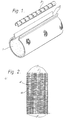
- a sleeve is provided with an integral ridge or protuberance running along each longitudinal edge. These two ridges are brought together and held together by a channel of generally C-shaped cross-section to maintain the sleeve in the wrapped-around configuration.
- the sleeve may be made by moulding or extruding a tubular member having a ridge or protuberance on the internal surface, slitting the member and the ridge along the length of the ridge, and turning the member inside out.
- the ridges preferably have a neck in cross-section in order that the channel be retained during recovery of the sleeve.
- the Ellis wraparound article is however expensive to manufacture and requires a large capital investment in fabrication and expansion equipment.
- the sleeve may be required to withstand relatively high internal pressures, for example in enclosing pressurised telecommunications cable splices, and cannot easily be reinforced by conventional techniques.
- Heat shrinkable tubular fabric articles have also been known for a very long time.
- Japanese laid open patent application 52-56393 to Sumitomo Electric Industries discloses a heat-recoverable braided resin tube which is installed over a wire bundle to produce a harness. Branch wires from the wire bundle can apparently be accommodated by drawing them out through the mesh at appropriate points. When the wires are installed the recoverable tube is heated to cause it to shrink down into tight contact with the wires.
- tubular fabric articles may be reinforced, as described in US Patent 3,669,157, but have not met with commercial success for various reasons. Only tubular articles are disclosed in these references and they therefore require access to a free end of the substrate for installation.
- the present invention provides a recoverable wraparound article which comprises a recoverable fabric cover portion, the fabric having a recovery ratio of at least 20% and edge regions provided with a mechanical closure for maintaining the edge regions in proximate relationship during recovery of the cover portion.
- Recovery ratio when expressed as a percentage, means the change in a dimension as a percentage of the dimension before recovery. The figure should be measured by determining the change that occurs on a single treatment by the appropriate agency such as heat, and not repeated and prolonged treatment over a long period of time.
- the recovery ratio of the free fabric to be at least 40%, especially at least 50%, particularly at least 75%.
- Fabrics can often have significant advantages when used as recoverable wrap-around articles, especially when used for environmmental sealing. Fabrics can provide excellent pressure retention due to their ability to accommodate hoop stresses. They are also highly resistant to cut or scratch damage due to their poor notch propagation. Also, they can easily be built up from or reinforced by fibres whose chief property is tensile strength. Glass and Kevlar (a trade name for an aromatic polyamide) are particularly useful. Such strength fibres will generally run transverse to the recoverable fibres and will thus give the wrap-around article considerable axial strength. They will also make a contribution to radial strength since radial expansion cannot occur without tension in the longitudinal fibres.
- the recoverable fabric of the invention preferably forms part of a dimensionally heat-recoverable article comprising a composite structure of the heat-recoverable fabric and a polymer matrix material wherein:
- the recoverable fabric of the invention provides the recoverable fibres of a recoverable composite structure comprising a cross-linked polymeric material and cross-linked recoverable fibres by virtue of which the composite structure is recoverable.
- Such a recoverable composite structure can be made by applying to the cross-linked recoverable fibres the polymeric material, and then cross-linking the polymeric material.
- the fibres may be cross-linked to increase their post-recovery strength, and a recovery stress of at least 1 MPa, preferably 1.5 to 5 MPa will be suitable.
- the polymeric material is desirably cross-linked to prevent it dripping or running during heat recovery, particularly by means of a torch. Too much cross-linking of the polymeric material will, however, reduce the recovery ratio of the composite. This may be a problem since a different of cross-linking treatment may be required in the fibres and the polymeric material. This is a reason for the two cross-linking steps being carried out separately above.
- the problem may arise due to different cross-linking responses (beam response in the case of irradiation cross-linking) of the materials used for the fibres and the polymeric material, or due to the treatment undergone by the fibres and polymeric material.
- This second effect includes the reduced beam response that of the fibres that results from their orientation produced by drawing to make them recoverable.
- the composite structure may, nonetheless, be produced using a single cross-linking step if the beam response of the recoverable fibres relative to that of the polymeric material is such that a post-irradiation recovery stress of the fibres, per se, of at least 1 MPa can be reached before the recovery ratio of the composite structure is reduced to a value of 70% of that of the unirradiated composite structure.
- the relative beam response may be produced by the presence of prorads in the recoverable fibres and/or antirads in the polymeric material.
- the fabric is incorporated into a flexible recoverable composite structure comprising the recoverable fabric and a polymeric matrix material laminated thereto, in which:
- Irradiation in addition to providing one means of cross-linking, can provide other features in the composite structure. If the fibres are irradiated, particularly in the presence of oxygen, before application of the polymeric material then a change in the surface properties of the fibres may occur (such as oxidation) which improves adhesion between the fibres and the polymeric material. An irradiation step after application of the polymeric material may also aid such bonding by forming a cross-linked bond between the two components of the composite structure.
- some mechanical interlocking between the fibres and the polymeric material may be provided.
- the recoverable article of this invention comprises heat-recoverable fibres having a minimum recovery stress of 10 MPa, more preferably 5 X 10 and usually at least 1 MPa at a temperature above the transition temperature of the fibres.
- a minimum recovery stress of 10 MPa more preferably 5 X 10 and usually at least 1 MPa at a temperature above the transition temperature of the fibres.
- There is no upper limit of recovery stress but in practice 200 MPa and more usually 100 MPa is the highest figure normally achievable with polymeric fibres.
- a range of 1.5 to 5 MPa will be typical.
- the fibres are preferably formed from a polymeric heat-recoverable material.
- a fabric can be made from substantially dimensionally stable fibres and then deformed for example by stretching to render it as a whole recoverable.
- recovery temperature of polymeric heat-recoverable materials is meant that temperature at which the recovery of the polymeric material will go substantially to completion. In general, the recovery temperature will be the crystalline melting transition temperature if the polymer is crystalline or the glass transition temperature if the polymer is amorphous.
- the heat-recoverable fibres are preferably formed from a polymeric material that imparts good physical properties and, in particular, good creep resistance to the fibres.
- Olefin polymers such as polyethylene and ethylene copolymers, polyamides, polyesters, acrylic polymers and other polymers capable of being cross- linked may be employed.
- a particularly preferred polymeric material for the fibres is based on polyethylene having a density of from 0.94 to 0.97/gms/cc, an Mw of from 80 X 10 3 to 200 X 10 3 and an M n of from 15 X-10 3 to 30 X 10 3 .
- the recovery temperature of the fibres is 60°C or more, most preferably from 80°C to 250°C, such as, for example, 120 - 150°C.
- the fibre When the fibre is cross-linked by irradiation it is convenient to incorporate the cross-linking step into manufacture of the fibre.
- the fibre can be extruded, stretched at a temperature below its melting temperature, preferably by an amount of from 800 to 2000 %, then subjected to irradiation to effect cross-linking.
- a less preferred way of making the fibre is to extrude the fibre, irradiate to cross-link, then heat the fibre, preferably to above its melting temperature, stretching the fibre, and then cooling the stretched fibre.
- High density polyethylene fibres are preferably irradiated with a dose of from about 5 to about 35 megarads, preferably from about 5 to about 25 megarads, and in particular from about 7 to about 18 megarads especially from 10 to about 18 megarads.
- the gel content of the cross-linked fibre is greater than 20%, preferably greater than 30%, most preferably greater than 40%. In practice, gel contents greater than 90% are not easily achievable.
- the heat-recoverable fabric can be made of only - heat-recoverable fibres as described above or can contain other fibres in addition to the heat-recoverable fibres. Where the fabric contains such other fibres, R in equation (1) relates only to the heat-recoverable fibre component.
- the fabric can be knitted, woven, non-woven, braided, or the like.
- the recoverable fibres can form part of the fabric itself as it is made or may be additional and inserted after production of the basic fabric.
- the fibres of the fabric may be monofilaments or multifilaments, and also staple fibres, wires or tapes. In a preferred embodiment the fabric is a woven fabric.
- a single ply weave may be used, or where a higher density or thicker fabric is desired a multiple ply weave may be used.
- the woven fabric can contain only heat-recoverable fibers or it can contain heat-recoverable fibres together with non-heat-recoverable fibres or filaments.
- the fabric can contain heat-recoverable fibres in one direction and non-heat-recoverable fibers in the other. This produces a heat-recoverable fabric which is recoverable in only one direction.
- the fabric can be woven in a pattern, for example, twill, broken twill, satin, sateen, Leno, plain, hop sack, sack, matt and various weave combinations.
- a single layer of fabric may be used or the article may comprise a laminate of two or more layers, optionally bonded together with a simple layer of adhesive or including a thicker layer interposed between the fabrics.
- the heat-recoverable fabric is preferably bonded to, and preferably embedded in, a polymer matrix material as mentioned above.
- the polymer matrix material should be capable of limited flow under pressure so that it retains the integrity of the composite structure without substantially impeding recovery of the fihces. It preferably has, at the aforesaid temperature, an elongation to break of greater than 50%, most preferably greater than 100% especially from 400 to 700%, and a 20% secant modulus of preferably at least 5 X 10 -2 MPa, most preferably at least 10 M Pa, measured at a strain rate of 300% per minute.
- the specified properties of the polymer matrix material need not necessarily apply after recovery.
- the polymer matrix material may eventually cure to a thermoset on heating, provided that the cure ate is sufficiently slow under the recovery conditions not to affect adversely the above- mentioned physical properties of the polymer matrix material during the recovery of the fibres.
- room temperature flexibility is desirable.
- the polymer matrix material can be either a thermoplastic or an elastomer.
- the former class of polymers include ethylene/vinyl acetate copolymers, ethylene/ethyl acrylate copolymers, polyethylenes including the linear low, low density and high density grades, polypropylene, polybutylene, polyesters, polyamides, polyetheramides, perfluoro- ethylene/ethylene copolymer and polyvinylidine fluoride.
- this can include acrylonitrile butadiene styrene block copolymer, acrylic elastomers including the acrylates and methacrylates and their copolymers, e.g.
- the matrix material can be cross-linked, for example a cross-linked ethylene/vinyl acetate copolymer, linear low density or high density grad-m-polyethylene or acrylic elastomer.
- the material can be cross-linked by irradiation or by other means such as chemical cross-linking using, for example, a peroxide cross-linking agent, provided that the physical properties of the matrix at the recovery temperature are as specified after the cross-linking step.
- the resulting extent of cross-linking allows the matrix to recover with the fabric and also prevents the matrix running or dripping during heat recovery.
- the recovery ratio of the composite after irradiation is preferably at least 50% especially at least 70% of that before irradiation.
- the heat-recoverable fabric is preferably bonded to the polymer matrix material, and this bonding may be adhesive, that is to say by chemical or physical surface interaction, or mechanical interlocking.
- the heat-recoverable fabric is embedded in the polymer matrix material thereby forming a composite structure.
- embedded is meant that the polymer matrix material surrounds at least a major portion of the fibre surface area of the fibres making up the fabric.
- the fibres are preferably totally surrounded by polymer matrix material, but it is possible and at times desirable that substantially less than the total fibre surface area be contacted by polymer material. Sufficient fibre area should be bonded to the polyzer matrix material or interlocked therewith to result in a composite structure which retains its integrity during recovery of the article.
- matrix is used to include materials which (partially or totally) surround the fibres and also those materials which are merely affixed to a surface of the fabric but which do not penetrate the interstices of the fabric.
- the polymer material at least on the surface of the composite structure facing the source of heat is substantially unstressed and is at least 0.03mm especially at least 0.2 particularly 0.2 to 2mm in thickness.
- Such polymeric material preferably softens during recovery but has a sufficiently high viscosity that it is retained by the fabric. This improves the ability of the composite structure to be heat recovered using a conventional propane torch. A heat-recoverable article having these characteristics is described in UK patent application No. 8300217.
- the ratio of the volume occupied by the heat-recoverable fibres of the fabric to the total volume of the composite is preferably at least about 0.01:1, more preferably from about 0.1:1 to about 0.8:1 and most preferably from about 0.2:1 to about 0.4:1.
- the heat-recoverable fibre volume in any given unit volume of composite should be chosen according to the fibre strength, polymer matrix strength and the integrity of the fibre/polymer matrix structure under recovery conditions.
- the composite structure can be formed for example by laminating or otherwise applying one or more layers of polymer matrix material to the heat-recoverable fabric. Sufficient heat and pressure is applied so that at least a major part of the fabric is(bonded to the polymer matrix material, or so that a significant amount of interlocking occurs. The result is a composite structure which on applicatin of heat recovers as a unit.
- the recoverable fabric cover portion comprises individual recoverable fibres
- the fibres at the edge regions must be indiviudally retained in order to prevent unravelling or fraying of the fabric during recovery.
- the recoverable fibres at one of the edge regions to be joined must be secured to the fibres (which may be the other end of the same fibres) at the other edge region in order that the fabric remains in the wrapped around configuration during recovery.
- the mechanical closure must therefore either grip the fibres directly or grip the matrix; where the closure grips the matrix a good chemical or physical bond or good interlocking must be provided between the fibres and the matrix at each edge. This may be accomplished by a variety of methods.
- a composite structure is formed at least at the edge regions.
- the individual fibre ends are fixed in the matrix, for example a polymer matrix which has sufficient strength to resist the recovery forces. It is in this case that a bond or interlocking between fibres and matrix is important.
- cross-linking, particularly irradiation, plays in this has been mentioned above in general terms.
- the recoverable fibres of the fabric do not terminate at the edge regions.
- they may be formed into loops, or the fabric itself looped around, so as to provide a passage for receiving an elongate member, for example a rod, which extends along the edge region.
- the closure means is adapted to grip a sufficient number of individual fibres in the edge regions, and may be for example a rod which - extends along the edge regions so as substantially to prevent them slipping from the closure on recovery and forming a 'run'.
- the first category is primarily applicable to woven fabrics having recoverable warp fibres.
- the problem here is that recovery of a simple piece of such fabric is likely to result in the warp fibres slipping through the weft causing fall-off of picks at each end of the fabric : the fabric does not therefore recover as a whole.
- One solution is to form a composite structure from the fabric by fixing the individual fibre ends in a relatively rigid composition to form closure elements which are fixed relative to the recoverable fibres and which therefore are able to transmit the recovery forces throughout the whole of the fabric.
- the fibres may be fixed by coating or impregnating the fabric with a composition which prevents the fabric from unravelling.
- the composition should be able to retain the integrity of the fabric under those conditions that will be applied to the fabric to cause-its recovery. Where, for example, the fabric is heat recoverable, the composition must be suitably heat resistant.
- the recovery temperature is preferably 60°C or more, more preferably 80-250°C, such as 120-150°C, and the composition should not melt unduly at such temperature.
- the composition may be a thermoplastic material or an elastomer.
- thermoplastic materials include ethylene/vinyl acetate copolymers, ethylene/ethyl acrylate copolymers, LLDPE,LDPE,MDPE,HDPE, polypropylene, polybutylene, polyesters, polyamides, polyetheramides, polyfluoroethylene/ethylene copolymers and polyvinylidene fluoride.
- Suitable elastomers include ABS block copolymers, acrylic elastomers, VAEs, polynorbornenes, polyurethanes and silicone elastomers.
- the composition is preferably a cross-linked material, for example cross-linked ethylene/vinyl acetate copolymer, LLDPE, HDPE or acrylic elastomers.
- the composition can be applied to the fabric over its entire surface and may be the same as, the previously mentioned polymeric material, or it may be applied at localised regions such as edge regions.
- the composition at these edge regions may act as first and second closure elements, or separate members may be bonded or welded to the composition.
- a further possibility is to use the composition at the edge portions of the fabric as a block : in this way a closure member may have projections which pass through the fabric but are fixed by the composition. These projections may pass through the composition as well as the fabric, or just through the fabric at a position immediately inwards of the composition.
- a base may be provided which carries a series of projections, or the projections may be arranged independently in which case each closure element comprises a set of discrete projections.
- the closure elements may interengage or be held together by a separate clamping member, which may for example be a C-shaped channel or a plurality of clamping devices.
- a separate clamping member which may for example be a C-shaped channel or a plurality of clamping devices.
- a variation on this involves the use of a flap or other elongate member having a row of projections on one of its surfaces.
- the two reinforced edges of the fabric (which in this variation constitute the closure elements) are overlapped when the sleeve is in the wrap-around configuration, and the projections are made to pass through the resulting double thickness of fabric.
- the projections may have the shape of arrow-heads or otherwise be provided with means to prevent their retraction once inserted through the fabric.
- a recoverable fabric composite allows the edge regions to be held together by various means, including the flap with projections mentioned above.
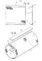
- various complex tubular articles such as bends, elbows and tees or branch-offs, may be made from simple tubular articles or from open sheet.
- the joining arrangement may be one or more lines of stitches or one or more staples.
- the portions joined together may be discrete or may merely be separate portions of a single piece of composite material.
- each line of stitches preferably has from 200-800 stitches per metre, and the line of stitches closest to an edge of the fabric is preferably separated from that edge by at least four rows of fibres and in the case of high float fabrics such as sateens where the high float is perpendicular to the join line, a spacing of at least six rows may be preferred.
- This will c-crespond to an edge overlap of at least 8-10mm, preferably at least 16 or 20mm for the fabric types preferred.
- a hem may, of course, be provided but this will increase the thickness of the fabric and this may not be desirable.
- the needles In order to reduce the possibility of breakage of the heat-recoverable fibres by the stitching (or stapling), the needles (or staples) should be very sharp at their tips and have a maximum used diameter of the same order of magnitide as the distance beween the heat-shrink fibres of the fabric.
- a further variation on this first category of closure mechanism is as follows.
- the fabric is laminated or impregnated with a composition to produce a composite sheet, preferably over its entire surface, and edge portions of the resulting sheet are folded over to provide closure members of increased thickness which can be held together by means for example of a closure channel.
- the composition used for this purpose may be any of those mentioned above for preventing edge portions of the fabric from unravelling in order that closure members may be bonded to the fabric or in order that projections may be forced through the fabric.
- the treatment of the fabric may therefore be identical in these two cases, and it is the techniques by which generally similarly shaped closure members are made that differ.
- the edge portions of the composite sheet may simply be folded over and optionally bonded to form the thickened closure elements.
- the thickened closure elements may be pre-formed in the factory, or formed on site if need be as part of the installation of the fabric around a suitable substrate.
- the closure elements may be held together by a third member such as a C-shaped channel which can enclose the two closure elements side-by-side.
- the two edge regions may be formed such that they interengage, and may optionally be held in interengagement by a further member.
- the second category can be considered as including those fabrics in which at least the recoverable fibre is effectively continuous, and does not appear to be a series of independant picks or ends.
- the most important instances are woven fabrics with recoverable weft made on a shuttle or rapier loom. (A shuttle loom produces a continuous weft in a boustrophedon pattern and a rapier loom can produce a similar effect from independant weft fibres by turning their ends back into the fabric.)
- This sort of fabric thus has inherent in its structure the means for attaching the closure member.
- a weft-recoverable fabric is woven having considerably thicker warp fibres at its edges than over its central region.
- the central region will form at least the major part of the wrap- around article, and the thickened edges will form the closure elements to be held together by a closure member or members.
- the thickened edge regions can be regarded as rails as illustrated in US Patent 3455336, since when they are brought together with the fabric in the wrapped configuration they show in cross-section a narrower portion adjacent to, and a wider portion remote from, the surface of the fabric.
- a channel, C-chaped in cross-section may be slid over these closure elements or rails to hold them together.
- the shape of the rails causes the channel to be retained during recovery of the fabric.
- a series of clips or clamps, or other means could be provided spaced along the length of the thickened warp fibres.
- a similar result can be achieved by inserting a rod or other elongate member into the weft at each edge region of a weft-recoverable fabric. It is not, of course, necessary that each such rod catches every pick, so long as the recovery forces can be uniformly transmitted to the rods to avoid unwanted buckling, unravelling, or fraying of the fabric on recovery.
- the two rods, which constitute the closure elements are brought together and held together by, for example, a C-shaped channel. The channel thus grips both rods and the fabric which surrounds them.
- Another embodiment within this category is, perhaps, most applicable to knitted or braided fabrics.
- the fabric (rather than just the recoverable fibres) which is effectively continuous and can provide, for example, a loop which can trap a rod or other elongate element.
- two such rods at opposite portions of the fabric are brought togther and securred by a C-chaped channel or other means.
- a fabric is knitted having a central portion of single thickness and edge portions of double thickness which are formed as closed loops. The fabric would thus have the shape of a dumb-bell in cross section.
- the fibre from which it is knitted may be recoverable, the fabric may have a warp or weft insertion of a recoverable fibre running from one of the loops to the other, or a stable fabric may be expanded or these ideas may be combined.
- An alternative to this is to produce a tubular fabric (by braiding, knitting or triaxial weaving, for instance) that has at least a component of recoverability running circumferentially, to flatten such a tube, and to use the flattened tube as a wrap- around sheet.
- a rod for example, may be inserted into the tube adjacent what is now each edge of the recoverable sheet. The two rods can be secured together to hold the flattened tube in a wrapped around configuration.
- Such a rod may be of any material which is sufficiently rigid in the installed product, such as a metal or plastic.
- the present invention also envisages a method of forming this type of closure element.
- a recoverable composite is folded over at an edge region to provide a loop, and this loop is held in a vice.
- a support is provided within the loop and the looped part of the composite is then recovered.
- the loop may be deformed to give it a desired shape. It has been found that the resulting closure member retains its shape on removal from the vice (this may be ensured by precoating the internal surface of the loop with an adhesive),and since the portion of the composite that constitutes the closure'member becomes dimensionally stable it has reduced tendency to pull out of any channel or closure means during recovery of the fabric article during its installation.
- the closure thus produced is new and this closure and its method of manufacture may be applied to recoverable wraparound articles other than the fabric articles described herein.
- closure means comprises teeth, clamping bars, pressure plates, or other frictionally engaging means for gripping the individual fibres in the edge regions. Suitable closure means of this type are described and claimed in copending UK patent application Serial No.822568 (Molinari). ⁇
- closure elements being situated at edge regions of the article, rather than at edges themselves since we wish to include also the provision of closure elements spaced some distance from the edges.
- a seal generally known as a flap
- Such a seal can conveniently be provided by that portion of the fabric which lies between the extreme edge and the adjacent closure member.
- the flap may be separate. In this way the functions of holding the sleeve edges together and of providing a seal can more readily be separated. This allows the various components to be optimised for their respective jobs.
- a separate flap is arranged to lie across the abutting or overlapping edges of the article and to be bonded to the edges. We have found that there are two requirements for a good permanent seal. Firstly the flap, the article and the adhesive must be chemically compatible to ensure a good bond or seal. Secondly, the moduli of the flap and the adhesive must be compatible if adhesion to the flap is not to fail during recovery of the article.
- the bond can be improved by surface treatment of the flap, for example by corona treatment or flame brushing, and by a good coating technique such as hopper coating.
- the adhesive is preferably an EVA or polyamide based hot-melt adhesive, particularly a polyamide having up to 10% of an acrylic rubber, based on the weight of the polyamide.
- the EVA should be beamed to a low dose, to retain a low modulus, comparable to that of the adhesive but sufficiently high to provide strength.
- the moduli of the flap and the adhesive preferably differ by less than 20%, more preferably by less than 10%, most preferably by less than 5%, based on whichever is the larger. This technique for providing a flap is applicable to continua as well as to fabrics, and also to intergral flaps.
- the closure elements may run substantially continuously along the edge regions or there may be a series of separated closure elements.
- An advantage of the closure elements being discontinuous is that the resulting article may have greater flexibility : this is useful where the article is to be shrunk down over a substrate of non-uniform cross-sectional size since the closure elements will be able to follow an irregular underlying shape.
- the closure elements may, by virtue of their shape, interlock or otherwise mechanically engage to hold the two edge regions of the fabric together during recovery.
- An example of such a closure is a zip.
- Each closure element can be regarded in such a case as possessing a feature which fixes it relative to the recoverable fibres at one edge region, and a feature by means of which it is engaged to the other closure elements.
- the fixing of the closure to the fabric may comprise sewing or stapling where the fabric forms part of a recoverable composite, or where other mean for preventing unravelling is provided.
- closure member which holds the two closure elements together, or which holds them a certain fixed distance apart.
- a sealant such as a mastic, or an adhesive such as a heat-activatable, particularly hot-melt,adhesive.
- a coating may be additional to the matrix referred to above for rendering the fabric substantially impervious, or it may be used alone.
- the matrix may have sufficient deformability or tackiness, preferably only at elevated temperatures, to act as a sealant or adhesive. The presence of an adhesive or sealant is of particular use when the fabric article is to be used for environmental sealing.
- Such means may be a mechanical device held in a biassed configuration by a material which releases it at a certain temperature or it may be a composition such as a paint or ink which changes colour at the required temperature. Such a composition is preferably applied to an exteral surface of the fabric article.
- Heat recoverable articles according to the invention comprising interwoven reinforcing fibres have been found to be particularly suitable for use in enclosing a splice between pressurized telecommunication cables.
- the recovered article is exceptionally resistant to,-the effects of pressure and preferred embodiments have sufficient hoop strength to resist rupturing under 70 KPa pressure (the pressure typically used in pressurized telecommunication systems) at ambient temperatures of such systems.
- 70 KPa pressure the pressure typically used in pressurized telecommunication systems
- the closure mechanism will be chosen accordinging to the desired degree of imperviousness, and the various flap systems described have been found to be ideal.
- a further use is in attaching , for example, a cable or a pipe to an elongate substrate. Due to the length of the cable, pipe, or substrate, the attachment means is desirably of the wraparound type. In many cases, such attachment must withstand severe mechanical and environmental stresses, and we have found that the article of the invention is particularly suitable.
- This type of use is the attachment of heating cables to the rotors of helicoptors. Here considerable centrifugal forces must be withstood under adverse weather conditions. The article of the invention has been found to function reliably
- Figure 1 is prior art. It shows a recoverable wrap-around sleeve 1 which has been extruded with integral closure rails 2. The rails are brought together to bring the sleeve into the wrap-around configuration, and held together by a closure channel 3 of substantially C-shaped cross-section.
- a sleeve is conveniently used for environmental protection of substrates such as cables or pipes.
- the sleeve is wrapped around the substrate and recovered, in this case by shrinking, to produce a tight fit.
- the sleeve may be coated on its inner surface with a sealing material to enhance the environmental protection provided.
- the sleeve may be heat-recoverable and the sealing material a heat-activatable adhesive so that the single step of heating causes recovery of the sleeve and activation of the adhesive.
- Figures 2-8 illustrate the invention, and in the first of them is shown a recoverable woven fabric 4.
- the fabric comprises a warp 5 and continuous recoverable weft 6.
- Closure elements 7 are provided at edge regions 8 of the fabric, and a channel such as that shown in Figure 1 could be used to hold them together.
- the means by which the closure elements are fixed relative to the recoverable fibres is inherent in the nature of the fabric since closure elements are threaded into the continuous weft and are trapped by it. Recovery of the weft will therefore draw the two closure elements together. It will generally be desirable that the closure elements are substantially rigid and if the bulk of the fabric is to be flexible, the closure elements are preferably rods inserted into the fabric after weaving.
- the closure elements may be provided by one or more warp ends of extra thickness used at each edge region 8 of the fabric.
- FIG. 3a and 3b An alternative technique for fixing the closure elements is shown in Figure 3a and 3b.
- This technique is applicable to all fabrics, and is especially applicable to knitted fabrics and warp-recoverable woven fabrics.
- edge region 8 of the fabric 4 is provided with a composition 9 which prevents the edges of the fabric from unravelling.
- the extent to which this composition is required will depend on how far from the edges of the fabric the closure elements 7 are to be provided since the friction between the fibres will reduce pull-out of the closure elements.
- the closure elements 7 may, for example, be bonded, welded, sewn or stapled to the edge regions 8 that have been reinforced with the composition 9.
- the closure elements themselves may have projections which pass through the fabric. These projections may pass through the composition as well as the fabric, or just through the fabric at a position immediately inwards of the composition.
- the composition which is preferably a cross-linked polymeric material,may extend over the whole surface area of the fabric, or may be localized at least at the--edges as drawn.
- the composition may merely be adhered to one or both surfaces of the fabric or it may form a matrix in which the fabric extends.
- FIG. 3b The situation in Figure 3b is similar, but here a series of projections is provided on a flap 10.
- This flap 10 is the means for maintaining the first and second closure elements together.
- the closure elements in this case being the edge regions that have been reinforced by composition 9.
- a cover 11 may be provided to engage the projections on the flap 10 to ensure it remains properly in position. It is not necessary, althouth is may sometimes be desirable,-to preform holes in the fabric for the projections of the flap 10 ( Figure 3b) or of the closure elements 7 ( Figure 3a).
- the projection may be sharp so that they can be forced through the fabric at the position desired, thus allowing the extent of overlay of the fabric to be chosen in the field.
- the fabric is effectively continuous and can provide a loop closed in cross-section to accommodate rods or other closure elements.
- the embodiment of Figure 4 is particularly applicable to braids, tubular knits and triaxial weaves.
- the fabric 4 is produced as a tube.
- the tube is flattened at then regarded as a flat sheet having loops at its edge regions 8 into which are inserted closure element 7.
- the two closure elements 7 may then be held together by a separate closure channel or other fastener. If desired the closure elements 7 may project from each end of the loops and be joined together remote from the sheet, although it has been found preferable to use a closure channel which overlies the fabric along the whole of the edge regions 8 and no serious damage to the fabric is found to occur.
- FIG. 5 A variation on this idea is shown in Figure 5, but here the central web of fabric 4 is of single thickness, and a closed loop 13 is provided at each edge regions 8.
- the loops 13 house the closure elements 7.
- This dumb-bell shaped fabric may be manufactured integrally by, for example, knitting.
- a flap is provided underlying the abutting rods 7, the purpose of which is to block any leak path.
- the flap 15 is integral with the fabric 4 and is simply that part of the fabric between an extreme edge of the fabric and one of the closure rods 7.
- a separate flap 16 is provided, and the modulus of the flap and of the adhesive bonding it to the fabric are preferably substantially equal as mentioned above.
- the fabric is shown around a cable 14, and when recovered the fabric will shrink down into engagement with the cable to provide an environmental seal.
- the fabric preferably in combination with a composition that renders it impermeable to air,may be used to protect a variety of substrates such as cables, cable splices and pipes.
- a splice case may be constructed by providing a liner around the substrate and within the fabric sleeve. See for example UK patent 1431167 and published patent applications 2059873 and 2069773.
- a liner in general has a central region of larger cross-section and end regions which taper down to the cables, thus providing a smooth transition from the large central splice bundle to the smaller cables.
- the fabric may have zones of different recovery ratios so that the unresolved recovery is, say, uniform over the entire substrate.
- splice case is intended to be able to retain a significant pressure
- means are preferably provided at each junction between the fabric and the underlying cable to put the bond between them out of peel.
- Such means may, for example, present a concave surface to pressure within the splice case thereby overcoming the forces that would cause peel.
- a branch-out between two or more cables, particularly telecommunications cables, may be sealed with the recoverable fabric article of the invention, and means may be provided to hold together circumferentially spaced regions of the fabric between the diverging cables.
- a suitable means for doing this is a two or three pronged clip which is positioned over an endof the fabric sleeve between the cables, see for example UK Patent 1604981.
- An alternative to a clip is to install around the cables a flexible seal which comprises an envelope which can undergo a change from lower to higher viscosity.
- the seal transforms the concave surfaces in the crutch region to a flat or convex surface to which the fabric article can seal. This seal is disclosed in copending UK patent application 8221597.
- branch-off can, however, be overcome by producing the fabric sleeve in the correct shape to accommodate two or more branching substrates.
- This solution is particularly applicable to fabrics, and offers significant advantages.
- a fabric can be produced, especially by knitting, which has for example one outlet at one end and two at another end. Such an article may still be wrap-around since closure mechanisms can be provided for each outlet where the substrate to be accommodated has no accessible end.
- the conduits for the main cable are preferably wrap-around, and the conduit for the drop wire tubular.
- the closure elements at regions 8 shown in figures 6 and 7 have been formed by folding over edges of the fabric 4 around support rods 7.
- the support rods should be substantially rigid or non-compresible under the conditions at least of installation of the finished product.
- the support rods 7 are preferably rods which extends the length of the closure member 3. Suitable materials are solid plastics or metals, or thermosetting adhesives.
- Splice cases formed from a recoverable fabric composite and closed by these closures were subjected to 100 cycles of each of the Bell and British Telecom tests.
- a splice case in air at 70 KPa is subjected to an eight hour temperature variation between -40 and +60°C.
- the splice case is in water, at 105 KPa and subjected to a four hour cycle between +5 and +50°C. No leaks were observed either through the fabric composite or through the closure.
- Figures 8a and b show an inventive technique for forming a closure element at an edge region of a recoverable fabric or continuum.
- An edge of a recoverable sheet 4 is folded over around a support 7 and secured in that folded configuration in a vice or other clamp 17.
- the support may be a solid rod or series of rod portions or it may be an adhesive coating on the sheet which later flows to fill the loop.
- a heat-activatable adhesive coating 18 is shown in addition to a support rod 7.
- the next step is recovery, preferable by heating the loop of recoverable sheet which extends above the vice 17 as drawn.
- the vice may conveniently act as a heat sink to limit recovery of the sheet to the loop.
- the loop shrinks and the adhesive is activated forming a tight and effectively solid closure rail at the edge of the sheet.
- the adhesive coating is preferably a thermosetting resin in order that the integrity of the rail is not lost during subsequent heating.
- the resulting rail has the advantage of being dimensionally stable. This is of considerable benefit in the closure systems illustrated in figures 6 and 7 since no movement of the edge regions of the sheet will occur on recovery during installation. Such movement is undesirable since it can weaken the frictional grip of the channel 3 and lead to pull out of the edge portions of the sleeve.
Abstract
Description
- This invention relates to recoverable articles, in―. particular to heat-recoverable articles.
- A heat-recoverable article is an article the dimensional configuration of which may be made substantially to change when subjected to heat treatment. Usually these articles recover, on heating, towards an original shape from which they have previously been deformed, but the term "heat-recoverable", as used herein, also includes an article which, on heating, adopts a new configuration, even if it has not been previously deformed.
- In their most common form, such articles comprise a heat-shrinkable sleeve made from a polymeric material exhibiting the property of elastic or plastic memory as described, for example, in U.S. Patents 2,027,962; 3,086,242 and 3,597,372. As is made clear in, for example, U.S. Patent 2,027,962, the original dimensionally heat-stable form may be a transient form in a continuous process in which, for example, an extruded tube is expanded, whilst hot, to a dimensionally heat-unstable form but, in other applications, a preformed dimensionally heat stable article is deformed to a dimensionally heat unstable form in a separate stage.
- In the production of heat recoverable articles, the polymeric material may be cross-linked at any stage in the production of the article that will enhance the desired dimensionally recoverability. One method of producing a heat-recoverable article comprises shaping the polymeric material into the desired heat-stable form, subsequently cross-linking the polymeric material, heating the article to a temperature above the crystalline melting point or, for amorphous materials the softening point, as the case may be, of the polymer, deforming the article and cooling the article whilst in the deformed state so that the deformed state of the article is retained. In use, since the deformed state of the article is heat-unstable, application of heat will cause the article to assume its original heat-stable shape. A further method comprises deforming a substantially non-crosslinked polymeric material at a temperature below the crystalline melting point or softening point of the material, fusing together parts of the material or a part or parts of the material and at least one other polymeric component to produce the configuration of at least one hollow heat-recoverable article and subsequently cross-linking the substantially non-cross-linked material.
- In other articles, an elastomeric member is held in a stretched state by a second member, which, upon heating weakens and thus allows the elastomeric member to recover. Heat-recoverable articles of this type are described, for example, in British Patent 1,440,524 in which an outer tubular elastomeric member is held in a stretched state by an inner tubular member.
- Heat-recoverable articles have found particular use in the environmental protection of elongate substrates such as for example splices in telecommunication cables.
- In addition to making the environmental seal the sleeve may be required to withstand an internal pressure, either because the complete splice enclosure is pressure tested for leaks, for example in the Bell cycle
- and British Telecom specifications, or because temperatures reached in service create a significant internal pressure. Whereas the known heat-recoverable sleeves are quite suitable for the conditions encountered with distribution splice enclosures, many larger telecommunication cables are internally pressurised to exclude moisture and the thicker-walled or reinforced sleeves which would be required to withstand such pressures long term are more difficult and expensive to manufacture and require greater skill to install in the field.
- It is often convenient to be able to install a recoverable article by wrapping it around the substrate thus avoiding totally severing the substrate. An example of this is during repair to a multi-conductor telephone cable : only a small number of the many conductors may be affected, and much time would be lost if the entire cable had to be severed in order to install a new tubular enclosure over the cable. Wrap-around products are also useful where space is limited: a wrap-around sleeve can be installed where the length of substrate accessible merely equals the width of the sleeve; a tubular sleeve however requires room for it to be shifted along the substrate away from the splice region while the splice is being made.
- Closures for recoverable wraparound articles have been known for many years and are described in the patent literature. Adhesives in general cannot resist the very large forces which can be generated during recovery of the article, and it has been found necessary for most applications to employ a wraparound sleeve provided with profiled edge regions,which can be engaged to form a mechanical closure. Although many such proposals are known, for its ease of assembly in the field, its strength and longitudinal flexibility under recovery conditions, the closure of Ellis US Patent 3,455,336 remains the only commercially successful design.
- In one embodiment, a sleeve is provided with an integral ridge or protuberance running along each longitudinal edge. These two ridges are brought together and held together by a channel of generally C-shaped cross-section to maintain the sleeve in the wrapped-around configuration. The sleeve may be made by moulding or extruding a tubular member having a ridge or protuberance on the internal surface, slitting the member and the ridge along the length of the ridge, and turning the member inside out. The ridges preferably have a neck in cross-section in order that the channel be retained during recovery of the sleeve. The precise cross-sectional shape of the ridges should be chosen in conjunction with the shape of the channel, and the sleeve can thus be moulded to the shape desired. The wrap-around system disclosed in this patent is the only one that has enjoyed wide commercial success to date.
- The Ellis wraparound article is however expensive to manufacture and requires a large capital investment in fabrication and expansion equipment. In addition, as previously mentioned, the sleeve may be required to withstand relatively high internal pressures, for example in enclosing pressurised telecommunications cable splices, and cannot easily be reinforced by conventional techniques.
- Heat shrinkable tubular fabric articles have also been known for a very long time. For example, Japanese laid open patent application 52-56393 to Sumitomo Electric Industries discloses a heat-recoverable braided resin tube which is installed over a wire bundle to produce a harness. Branch wires from the wire bundle can apparently be accommodated by drawing them out through the mesh at appropriate points. When the wires are installed the recoverable tube is heated to cause it to shrink down into tight contact with the wires.
- It has also been proposed, in U.S.
Patent 3 669 157 to Carolina Narrow Fabric Company and in Japanese Patent 53-13805 to Matsushita, to provide heat-shrinkable tubular fabric articles which may be impregnated with certain thermosetting resins. - These tubular fabric articles may be reinforced, as described in US Patent 3,669,157, but have not met with commercial success for various reasons. Only tubular articles are disclosed in these references and they therefore require access to a free end of the substrate for installation.
- The present invention provides a recoverable wraparound article which comprises a recoverable fabric cover portion, the fabric having a recovery ratio of at least 20% and edge regions provided with a mechanical closure for maintaining the edge regions in proximate relationship during recovery of the cover portion.
- Recovery ratio, when expressed as a percentage, means the change in a dimension as a percentage of the dimension before recovery. The figure should be measured by determining the change that occurs on a single treatment by the appropriate agency such as heat, and not repeated and prolonged treatment over a long period of time. We prefer the recovery ratio of the free fabric to be at least 40%, especially at least 50%, particularly at least 75%.
- Fabrics can often have significant advantages when used as recoverable wrap-around articles, especially when used for environmmental sealing. Fabrics can provide excellent pressure retention due to their ability to accommodate hoop stresses. They are also highly resistant to cut or scratch damage due to their poor notch propagation. Also, they can easily be built up from or reinforced by fibres whose chief property is tensile strength. Glass and Kevlar (a trade name for an aromatic polyamide) are particularly useful. Such strength fibres will generally run transverse to the recoverable fibres and will thus give the wrap-around article considerable axial strength. They will also make a contribution to radial strength since radial expansion cannot occur without tension in the longitudinal fibres.
- In one embodiment, the recoverable fabric of the invention preferably forms part of a dimensionally heat-recoverable article comprising a composite structure of the heat-recoverable fabric and a polymer matrix material wherein:
- (a) the heat-recoverable fabric comprises fibres that will recover when heated, the fibres having a recovery stress Y of at least 5
X 10-2 MPa at a temperature above their recovery temperature; and - (b) the polymer matrix material has an elongation/ temperature profile such that there exists a temperature (T) which is at or above the recovery temperature of the fibres at which temperature the polymer matrix material has an elongation to break of greater than 20% and a 20% secant modulus X of at least 10 MPa (measured at a strain rate of 300% per minute), and at which temperature the inequality (1) is satisfied:

- In a further embodiment, the recoverable fabric of the invention provides the recoverable fibres of a recoverable composite structure comprising a cross-linked polymeric material and cross-linked recoverable fibres by virtue of which the composite structure is recoverable.
- Such a recoverable composite structure can be made by applying to the cross-linked recoverable fibres the polymeric material, and then cross-linking the polymeric material.
- The fibres may be cross-linked to increase their post-recovery strength, and a recovery stress of at least 1 MPa, preferably 1.5 to 5 MPa will be suitable. The polymeric material is desirably cross-linked to prevent it dripping or running during heat recovery, particularly by means of a torch. Too much cross-linking of the polymeric material will, however, reduce the recovery ratio of the composite. This may be a problem since a different of cross-linking treatment may be required in the fibres and the polymeric material. This is a reason for the two cross-linking steps being carried out separately above. The problem may arise due to different cross-linking responses (beam response in the case of irradiation cross-linking) of the materials used for the fibres and the polymeric material, or due to the treatment undergone by the fibres and polymeric material. This second effect includes the reduced beam response that of the fibres that results from their orientation produced by drawing to make them recoverable.
- The composite structure may, nonetheless, be produced using a single cross-linking step if the beam response of the recoverable fibres relative to that of the polymeric material is such that a post-irradiation recovery stress of the fibres, per se, of at least 1 MPa can be reached before the recovery ratio of the composite structure is reduced to a value of 70% of that of the unirradiated composite structure.
- The relative beam response may be produced by the presence of prorads in the recoverable fibres and/or antirads in the polymeric material.
- In a preferred embodiment of the invention the fabric is incorporated into a flexible recoverable composite structure comprising the recoverable fabric and a polymeric matrix material laminated thereto, in which:
- (a) the recoverable.fabric comprises a cross-linked recoverable polyolefin having a recovery stress of 1.5 to 5 MPa; and
- (b) the matrix is cross-linked such that the recovery ratio available in the composite is at least 65% of that available in the free fabric, and the polymeric matrix material, per se, after irradiation has room temperature elongation 400-700% measured at a strain rate 300% minute.
- Irradiation, in addition to providing one means of cross-linking, can provide other features in the composite structure. If the fibres are irradiated, particularly in the presence of oxygen, before application of the polymeric material then a change in the surface properties of the fibres may occur (such as oxidation) which improves adhesion between the fibres and the polymeric material. An irradiation step after application of the polymeric material may also aid such bonding by forming a cross-linked bond between the two components of the composite structure.
- Also, or instead depending on the conditions under which the polymeric material is applied, some mechanical interlocking between the fibres and the polymeric material may be provided.
- In general the recoverable article of this invention comprises heat-recoverable fibres having a minimum recovery stress of 10 MPa, more preferably 5 X 10 and usually at least 1 MPa at a temperature above the transition temperature of the fibres. There is no upper limit of recovery stress, but in practice 200 MPa and more usually 100 MPa is the highest figure normally achievable with polymeric fibres. As mentioned above, a range of 1.5 to 5 MPa will be typical.
- The fibres are preferably formed from a polymeric heat-recoverable material. Alternatively, a fabric can be made from substantially dimensionally stable fibres and then deformed for example by stretching to render it as a whole recoverable. By the "recovery temperature" of polymeric heat-recoverable materials is meant that temperature at which the recovery of the polymeric material will go substantially to completion. In general, the recovery temperature will be the crystalline melting transition temperature if the polymer is crystalline or the glass transition temperature if the polymer is amorphous.
- The heat-recoverable fibres are preferably formed from a polymeric material that imparts good physical properties and, in particular, good creep resistance to the fibres. Olefin polymers such as polyethylene and ethylene copolymers, polyamides, polyesters, acrylic polymers and other polymers capable of being cross- linked may be employed. A particularly preferred polymeric material for the fibres is based on polyethylene having a density of from 0.94 to 0.97/gms/cc, an Mw of from 80
X 103 to 200 X 103 and an Mn of from 15 X-103 to 30 X 10 3. - Preferably the recovery temperature of the fibres is 60°C or more, most preferably from 80°C to 250°C, such as, for example, 120 - 150°C.
- When the fibre is cross-linked by irradiation it is convenient to incorporate the cross-linking step into manufacture of the fibre. The fibre can be extruded, stretched at a temperature below its melting temperature, preferably by an amount of from 800 to 2000 %, then subjected to irradiation to effect cross-linking. A less preferred way of making the fibre is to extrude the fibre, irradiate to cross-link, then heat the fibre, preferably to above its melting temperature, stretching the fibre, and then cooling the stretched fibre. High density polyethylene fibres are preferably irradiated with a dose of from about 5 to about 35 megarads, preferably from about 5 to about 25 megarads, and in particular from about 7 to about 18 megarads especially from 10 to about 18 megarads. Usually the gel content of the cross-linked fibre is greater than 20%, preferably greater than 30%, most preferably greater than 40%. In practice, gel contents greater than 90% are not easily achievable.
- The heat-recoverable fabric can be made of only - heat-recoverable fibres as described above or can contain other fibres in addition to the heat-recoverable fibres. Where the fabric contains such other fibres, R in equation (1) relates only to the heat-recoverable fibre component. The fabric can be knitted, woven, non-woven, braided, or the like. The recoverable fibres can form part of the fabric itself as it is made or may be additional and inserted after production of the basic fabric. The fibres of the fabric may be monofilaments or multifilaments, and also staple fibres, wires or tapes. In a preferred embodiment the fabric is a woven fabric. A single ply weave may be used, or where a higher density or thicker fabric is desired a multiple ply weave may be used. The woven fabric can contain only heat-recoverable fibers or it can contain heat-recoverable fibres together with non-heat-recoverable fibres or filaments. For example, the fabric can contain heat-recoverable fibres in one direction and non-heat-recoverable fibers in the other. This produces a heat-recoverable fabric which is recoverable in only one direction. The fabric can be woven in a pattern, for example, twill, broken twill, satin, sateen, Leno, plain, hop sack, sack, matt and various weave combinations. A single layer of fabric may be used or the article may comprise a laminate of two or more layers, optionally bonded together with a simple layer of adhesive or including a thicker layer interposed between the fabrics.
- The heat-recoverable fabric is preferably bonded to, and preferably embedded in, a polymer matrix material as mentioned above. At or above the recovery temperature of the fibres the polymer matrix material should be capable of limited flow under pressure so that it retains the integrity of the composite structure without substantially impeding recovery of the fihces. It preferably has, at the aforesaid temperature, an elongation to break of greater than 50%, most preferably greater than 100% especially from 400 to 700%, and a 20% secant modulus of preferably at least 5 X 10⁻² MPa, most preferably at least 10 MPa, measured at a strain rate of 300% per minute.
- The specified properties of the polymer matrix material need not necessarily apply after recovery. Thus, for example, the polymer matrix material may eventually cure to a thermoset on heating, provided that the cure ate is sufficiently slow under the recovery conditions not to affect adversely the above- mentioned physical properties of the polymer matrix material during the recovery of the fibres. However, for many purposes, room temperature flexibility is desirable.
- The polymer matrix material can be either a thermoplastic or an elastomer. Examples of the former class of polymers include ethylene/vinyl acetate copolymers, ethylene/ethyl acrylate copolymers, polyethylenes including the linear low, low density and high density grades, polypropylene, polybutylene, polyesters, polyamides, polyetheramides, perfluoro- ethylene/ethylene copolymer and polyvinylidine fluoride. Considering the second class of materials this can include acrylonitrile butadiene styrene block copolymer, acrylic elastomers including the acrylates and methacrylates and their copolymers, e.g. polybutyl acrylate, and poly 2-ethyl hexylacrylate, the high vinyl acetate copolymers with ethylene (VAE's), poly- norbornene, polyurethanes and silicone elastomers and the like. The matrix material can be cross-linked, for example a cross-linked ethylene/vinyl acetate copolymer, linear low density or high density grad-m-polyethylene or acrylic elastomer. The material can be cross-linked by irradiation or by other means such as chemical cross-linking using, for example, a peroxide cross-linking agent, provided that the physical properties of the matrix at the recovery temperature are as specified after the cross-linking step. Where irradiation is used, a dose of 10 megarads or less, in particular from 3-7 megarads, is preferred. The resulting extent of cross-linking allows the matrix to recover with the fabric and also prevents the matrix running or dripping during heat recovery. The recovery ratio of the composite after irradiation is preferably at least 50% especially at least 70% of that before irradiation. These dose values may be regarded as typical for olefinic polymers such as polyethylene of low orientation, and the skilled man will be able to select suitable dose values depending on the presence of various concentrations of prorads or antirads, if any.
- The heat-recoverable fabric is preferably bonded to the polymer matrix material, and this bonding may be adhesive, that is to say by chemical or physical surface interaction, or mechanical interlocking.
- Most preferable the heat-recoverable fabric is embedded in the polymer matrix material thereby forming a composite structure. By "embedded" is meant that the polymer matrix material surrounds at least a major portion of the fibre surface area of the fibres making up the fabric.
- The fibres are preferably totally surrounded by polymer matrix material, but it is possible and at times desirable that substantially less than the total fibre surface area be contacted by polymer material. Sufficient fibre area should be bonded to the polyzer matrix material or interlocked therewith to result in a composite structure which retains its integrity during recovery of the article. For the avoidance of doubt it is here stated that the term matrix is used to include materials which (partially or totally) surround the fibres and also those materials which are merely affixed to a surface of the fabric but which do not penetrate the interstices of the fabric.
- Preferably the polymer material at least on the surface of the composite structure facing the source of heat is substantially unstressed and is at least 0.03mm especially at least 0.2 particularly 0.2 to 2mm in thickness. Such polymeric material preferably softens during recovery but has a sufficiently high viscosity that it is retained by the fabric. This improves the ability of the composite structure to be heat recovered using a conventional propane torch. A heat-recoverable article having these characteristics is described in UK patent application No. 8300217.
- In the composite structure, the ratio of the volume occupied by the heat-recoverable fibres of the fabric to the total volume of the composite is preferably at least about 0.01:1, more preferably from about 0.1:1 to about 0.8:1 and most preferably from about 0.2:1 to about 0.4:1.
- In the composite structure the heat-recoverable fibre volume in any given unit volume of composite should be chosen according to the fibre strength, polymer matrix strength and the integrity of the fibre/polymer matrix structure under recovery conditions.
- We have found that an acceptable recoverable product results if the inequality (1) mentioned above is satisfied, viz: --


- The composite structure can be formed for example by laminating or otherwise applying one or more layers of polymer matrix material to the heat-recoverable fabric. Sufficient heat and pressure is applied so that at least a major part of the fabric is(bonded to the polymer matrix material, or so that a significant amount of interlocking occurs. The result is a composite structure which on applicatin of heat recovers as a unit.
- Other methods of applying the fabric to the matrix can be used, for example, impregnation, solution coating, slurry coating, powder coating, reactive pre-polymers, e.g. acrylic prepolymers activated by UV or peroxide, and the like. In any application method employed sufficient heat to cause the fabric to recover to any significant extent should be avoided, unless the fabric is suitably restrained from recovery.
- Since the recoverable fabric cover portion comprises individual recoverable fibres, the fibres at the edge regions must be indiviudally retained in order to prevent unravelling or fraying of the fabric during recovery. Also the recoverable fibres at one of the edge regions to be joined must be secured to the fibres (which may be the other end of the same fibres) at the other edge region in order that the fabric remains in the wrapped around configuration during recovery. The mechanical closure must therefore either grip the fibres directly or grip the matrix; where the closure grips the matrix a good chemical or physical bond or good interlocking must be provided between the fibres and the matrix at each edge. This may be accomplished by a variety of methods.
- In one embodiment a composite structure is formed at least at the edge regions. Thus, the individual fibre ends are fixed in the matrix, for example a polymer matrix which has sufficient strength to resist the recovery forces. It is in this case that a bond or interlocking between fibres and matrix is important. The part that cross-linking, particularly irradiation, plays in this has been mentioned above in general terms.
- In another embodiment the recoverable fibres of the fabric do not terminate at the edge regions. For example, they may be formed into loops, or the fabric itself looped around, so as to provide a passage for receiving an elongate member, for example a rod, which extends along the edge region.
- In yet another embodiment the closure means is adapted to grip a sufficient number of individual fibres in the edge regions, and may be for example a rod which - extends along the edge regions so as substantially to prevent them slipping from the closure on recovery and forming a 'run'.
- It is also possible to bond profiles on to the edge regions of the article to form, for example, a closure as described in US Patent 3,455,336, and our claims include this possibility, although at present this is not the preferred method of forming the mechanical closure means. Such a bond could be enhanced by cross-linking, especially by irradiation if the closure itself was susceptible to cross-linking. An alternative in some mechanical connection, for example stitching or stapling, between the closure and the article.
- The above mentioned embodiments of closures in accordance with this invention will now be discussed in more detail.
- The first category is primarily applicable to woven fabrics having recoverable warp fibres. The problem here is that recovery of a simple piece of such fabric is likely to result in the warp fibres slipping through the weft causing fall-off of picks at each end of the fabric : the fabric does not therefore recover as a whole. One solution is to form a composite structure from the fabric by fixing the individual fibre ends in a relatively rigid composition to form closure elements which are fixed relative to the recoverable fibres and which therefore are able to transmit the recovery forces throughout the whole of the fabric.
- The fibres may be fixed by coating or impregnating the fabric with a composition which prevents the fabric from unravelling. The composition should be able to retain the integrity of the fabric under those conditions that will be applied to the fabric to cause-its recovery. Where, for example, the fabric is heat recoverable, the composition must be suitably heat resistant. The recovery temperature is preferably 60°C or more, more preferably 80-250°C, such as 120-150°C, and the composition should not melt unduly at such temperature. The composition may be a thermoplastic material or an elastomer. Examples of thermoplastic materials include ethylene/vinyl acetate copolymers, ethylene/ethyl acrylate copolymers, LLDPE,LDPE,MDPE,HDPE, polypropylene, polybutylene, polyesters, polyamides, polyetheramides, polyfluoroethylene/ethylene copolymers and polyvinylidene fluoride. Suitable elastomers include ABS block copolymers, acrylic elastomers, VAEs, polynorbornenes, polyurethanes and silicone elastomers. The composition is preferably a cross-linked material, for example cross-linked ethylene/vinyl acetate copolymer, LLDPE, HDPE or acrylic elastomers.
- The composition can be applied to the fabric over its entire surface and may be the same as, the previously mentioned polymeric material, or it may be applied at localised regions such as edge regions. The composition at these edge regions may act as first and second closure elements, or separate members may be bonded or welded to the composition.
- A further possibility is to use the composition at the edge portions of the fabric as a block : in this way a closure member may have projections which pass through the fabric but are fixed by the composition. These projections may pass through the composition as well as the fabric, or just through the fabric at a position immediately inwards of the composition. A base may be provided which carries a series of projections, or the projections may be arranged independently in which case each closure element comprises a set of discrete projections.
- The closure elements may interengage or be held together by a separate clamping member, which may for example be a C-shaped channel or a plurality of clamping devices. A variation on this involves the use of a flap or other elongate member having a row of projections on one of its surfaces. The two reinforced edges of the fabric (which in this variation constitute the closure elements) are overlapped when the sleeve is in the wrap-around configuration, and the projections are made to pass through the resulting double thickness of fabric. The projections may have the shape of arrow-heads or otherwise be provided with means to prevent their retraction once inserted through the fabric.
- The ability of a recoverable fabric composite to be penetrated allows the edge regions to be held together by various means, including the flap with projections mentioned above. Also, various complex tubular articles, such as bends, elbows and tees or branch-offs, may be made from simple tubular articles or from open sheet. In general terms, therefore, two or more portions of composite structure may be joined together by means of a mechanical joining arrangement that penetrates the fabric. The joining arrangement may be one or more lines of stitches or one or more staples. The portions joined together may be discrete or may merely be separate portions of a single piece of composite material. Where stitching is used each line of stitches preferably has from 200-800 stitches per metre, and the line of stitches closest to an edge of the fabric is preferably separated from that edge by at least four rows of fibres and in the case of high float fabrics such as sateens where the high float is perpendicular to the join line, a spacing of at least six rows may be preferred. This will c-crespond to an edge overlap of at least 8-10mm, preferably at least 16 or 20mm for the fabric types preferred. A hem may, of course, be provided but this will increase the thickness of the fabric and this may not be desirable. In order to reduce the possibility of breakage of the heat-recoverable fibres by the stitching (or stapling), the needles (or staples) should be very sharp at their tips and have a maximum used diameter of the same order of magnitide as the distance beween the heat-shrink fibres of the fabric.
- A further variation on this first category of closure mechanism is as follows. The fabric is laminated or impregnated with a composition to produce a composite sheet, preferably over its entire surface, and edge portions of the resulting sheet are folded over to provide closure members of increased thickness which can be held together by means for example of a closure channel. The composition used for this purpose may be any of those mentioned above for preventing edge portions of the fabric from unravelling in order that closure members may be bonded to the fabric or in order that projections may be forced through the fabric. The treatment of the fabric may therefore be identical in these two cases, and it is the techniques by which generally similarly shaped closure members are made that differ.
- The edge portions of the composite sheet may simply be folded over and optionally bonded to form the thickened closure elements. The thickened closure elements may be pre-formed in the factory, or formed on site if need be as part of the installation of the fabric around a suitable substrate. The closure elements may be held together by a third member such as a C-shaped channel which can enclose the two closure elements side-by-side. The two edge regions may be formed such that they interengage, and may optionally be held in interengagement by a further member.
- The second category can be considered as including those fabrics in which at least the recoverable fibre is effectively continuous, and does not appear to be a series of independant picks or ends. The most important instances are woven fabrics with recoverable weft made on a shuttle or rapier loom. (A shuttle loom produces a continuous weft in a boustrophedon pattern and a rapier loom can produce a similar effect from independant weft fibres by turning their ends back into the fabric.) This sort of fabric thus has inherent in its structure the means for attaching the closure member.
- In one embodiment of this category, a weft-recoverable fabric is woven having considerably thicker warp fibres at its edges than over its central region. The central region will form at least the major part of the wrap- around article, and the thickened edges will form the closure elements to be held together by a closure member or members. In general, it will be necessary for only a single warp thread at each edge of the fabric to be thicker, although if the difference in thickness referred to is only small it may be preferable to employ several thicker fibres at each edge. The thickened edge regions can be regarded as rails as illustrated in US Patent 3455336, since when they are brought together with the fabric in the wrapped configuration they show in cross-section a narrower portion adjacent to, and a wider portion remote from, the surface of the fabric. A channel, C-chaped in cross-section, may be slid over these closure elements or rails to hold them together. The shape of the rails causes the channel to be retained during recovery of the fabric. Alternatively, a series of clips or clamps, or other means, could be provided spaced along the length of the thickened warp fibres.
- A similar result can be achieved by inserting a rod or other elongate member into the weft at each edge region of a weft-recoverable fabric. It is not, of course, necessary that each such rod catches every pick, so long as the recovery forces can be uniformly transmitted to the rods to avoid unwanted buckling, unravelling, or fraying of the fabric on recovery. As before, the two rods, which constitute the closure elements are brought together and held together by, for example, a C-shaped channel. The channel thus grips both rods and the fabric which surrounds them.
- Another embodiment within this category is, perhaps, most applicable to knitted or braided fabrics. Here it is the fabric (rather than just the recoverable fibres) which is effectively continuous and can provide, for example, a loop which can trap a rod or other elongate element. As above, two such rods at opposite portions of the fabric are brought togther and securred by a C-chaped channel or other means. In one example a fabric is knitted having a central portion of single thickness and edge portions of double thickness which are formed as closed loops. The fabric would thus have the shape of a dumb-bell in cross section. The fibre from which it is knitted may be recoverable, the fabric may have a warp or weft insertion of a recoverable fibre running from one of the loops to the other, or a stable fabric may be expanded or these ideas may be combined. An alternative to this is to produce a tubular fabric (by braiding, knitting or triaxial weaving, for instance) that has at least a component of recoverability running circumferentially, to flatten such a tube, and to use the flattened tube as a wrap- around sheet. A rod, for example, may be inserted into the tube adjacent what is now each edge of the recoverable sheet. The two rods can be secured together to hold the flattened tube in a wrapped around configuration.
- Such a rod may be of any material which is sufficiently rigid in the installed product, such as a metal or plastic.
- The present invention also envisages a method of forming this type of closure element. A recoverable composite is folded over at an edge region to provide a loop, and this loop is held in a vice. A support is provided within the loop and the looped part of the composite is then recovered. During recovery, the loop may be deformed to give it a desired shape. It has been found that the resulting closure member retains its shape on removal from the vice (this may be ensured by precoating the internal surface of the loop with an adhesive),and since the portion of the composite that constitutes the closure'member becomes dimensionally stable it has reduced tendency to pull out of any channel or closure means during recovery of the fabric article during its installation. The closure thus produced is new and this closure and its method of manufacture may be applied to recoverable wraparound articles other than the fabric articles described herein.
- In the third category the closure means comprises teeth, clamping bars, pressure plates, or other frictionally engaging means for gripping the individual fibres in the edge regions. Suitable closure means of this type are described and claimed in copending UK patent application Serial No.822568 (Molinari). ――
- Reference is made to the closure elements being situated at edge regions of the article, rather than at edges themselves since we wish to include also the provision of closure elements spaced some distance from the edges. When the wrap-around article is used for environmental sealing it may be desirable to provide a seal (generally known as a flap) between the two edges of the fabric which are brought together when the fabric is in the wrap-around configuration. Such a seal can conveniently be provided by that portion of the fabric which lies between the extreme edge and the adjacent closure member.
- Instead of providing the flap as an integral part of the sleeve, it may be separate. In this way the functions of holding the sleeve edges together and of providing a seal can more readily be separated. This allows the various components to be optimised for their respective jobs. A separate flap is arranged to lie across the abutting or overlapping edges of the article and to be bonded to the edges. We have found that there are two requirements for a good permanent seal. Firstly the flap, the article and the adhesive must be chemically compatible to ensure a good bond or seal. Secondly, the moduli of the flap and the adhesive must be compatible if adhesion to the flap is not to fail during recovery of the article. The bond can be improved by surface treatment of the flap, for example by corona treatment or flame brushing, and by a good coating technique such as hopper coating. The adhesive is preferably an EVA or polyamide based hot-melt adhesive, particularly a polyamide having up to 10% of an acrylic rubber, based on the weight of the polyamide. We have found excellent results using a non-recoverable EVA based flap, especially one based on a blend of- different EVAs. The EVA should be beamed to a low dose, to retain a low modulus, comparable to that of the adhesive but sufficiently high to provide strength. The moduli of the flap and the adhesive preferably differ by less than 20%, more preferably by less than 10%, most preferably by less than 5%, based on whichever is the larger. This technique for providing a flap is applicable to continua as well as to fabrics, and also to intergral flaps.
- The closure elements may run substantially continuously along the edge regions or there may be a series of separated closure elements. An advantage of the closure elements being discontinuous is that the resulting article may have greater flexibility : this is useful where the article is to be shrunk down over a substrate of non-uniform cross-sectional size since the closure elements will be able to follow an irregular underlying shape.
- The closure elements may, by virtue of their shape, interlock or otherwise mechanically engage to hold the two edge regions of the fabric together during recovery. An example of such a closure is a zip. Each closure element can be regarded in such a case as possessing a feature which fixes it relative to the recoverable fibres at one edge region, and a feature by means of which it is engaged to the other closure elements. The fixing of the closure to the fabric may comprise sewing or stapling where the fabric forms part of a recoverable composite, or where other mean for preventing unravelling is provided.
- In another arrangement there may be a separate closure member which holds the two closure elements together, or which holds them a certain fixed distance apart.--The two ideas can of course be combined, in which case the closure elements may interlock and be reinforced by a closure member
- Whatever the closure mechanism,it will often be desirable to coat the fabric on that surface which will be inwardly facing when the article is in the wrapped configuration with a sealant, such as a mastic, or an adhesive such as a heat-activatable, particularly hot-melt,adhesive. Such a coating may be additional to the matrix referred to above for rendering the fabric substantially impervious, or it may be used alone. Alternatively, it is possible that the matrix may have sufficient deformability or tackiness, preferably only at elevated temperatures, to act as a sealant or adhesive. The presence of an adhesive or sealant is of particular use when the fabric article is to be used for environmental sealing.
- It may be found useful to provide means for indicating when complete recovery of the fabric has occured or when any internal adhesive coating has been properly activated. Where the fabric is heat-recoverable and the adhesive is heat-activatable, such means may be a mechanical device held in a biassed configuration by a material which releases it at a certain temperature or it may be a composition such as a paint or ink which changes colour at the required temperature. Such a composition is preferably applied to an exteral surface of the fabric article.
- Heat recoverable articles according to the invention comprising interwoven reinforcing fibres have been found to be particularly suitable for use in enclosing a splice between pressurized telecommunication cables. The recovered article is exceptionally resistant to,-the effects of pressure and preferred embodiments have sufficient hoop strength to resist rupturing under 70 KPa pressure (the pressure typically used in pressurized telecommunication systems) at ambient temperatures of such systems. When the fabric is used in conjunction with a matrix material or polymeric coating it can easily provide sufficient imperviousness to retain such pressure over long periods of time. The closure mechanism will be chosen acording to the desired degree of imperviousness, and the various flap systems described have been found to be ideal. Other uses include the repair to lengths of cable or the repair or protection of pipes or pipe joints for,say,gas oil or air. A further use is in attaching , for example, a cable or a pipe to an elongate substrate. Due to the length of the cable, pipe, or substrate, the attachment means is desirably of the wraparound type. In many cases, such attachment must withstand severe mechanical and environmental stresses, and we have found that the article of the invention is particularly suitable. One example of this type of use is the attachment of heating cables to the rotors of helicoptors. Here considerable centrifugal forces must be withstood under adverse weather conditions. The article of the invention has been found to function reliably
- The invention will now be further illustrated with reference to the accompanying drawings, in which:
- Figure 1 shows a known extruded wrap-around recoverable sleeve and a closure channel;
- Figure 2 shows a piece of recoverable fabric, with closure elements;
- Figures 3a+b show, an alternative arrangement for securing closure elements to a recoverable fabric and a closure member;
- Figure 4 shows a flattened recoverable fabric tube containing closure elements;
- Figure 5 shows a recoverable fabric incorporating loops for housing closure elements;
- Figures 6 and 7 show two arrangements whereby edge regions of a recoverable sleeve are held by a closure channel member; and
- Figures 8a+b show a technique for forming a rail at an edge region of a recoverable sheet.
- Figure 1 is prior art. It shows a recoverable wrap-around sleeve 1 which has been extruded with integral closure rails 2. The rails are brought together to bring the sleeve into the wrap-around configuration, and held together by a
closure channel 3 of substantially C-shaped cross-section. Such a sleeve is conveniently used for environmental protection of substrates such as cables or pipes. The sleeve is wrapped around the substrate and recovered, in this case by shrinking, to produce a tight fit. The sleeve may be coated on its inner surface with a sealing material to enhance the environmental protection provided. The sleeve may be heat-recoverable and the sealing material a heat-activatable adhesive so that the single step of heating causes recovery of the sleeve and activation of the adhesive. - Figures 2-8 illustrate the invention, and in the first of them is shown a recoverable woven fabric 4. The fabric comprises a warp 5 and continuous
recoverable weft 6.Closure elements 7 are provided atedge regions 8 of the fabric, and a channel such as that shown in Figure 1 could be used to hold them together. In this embodiment, the means by which the closure elements are fixed relative to the recoverable fibres is inherent in the nature of the fabric since closure elements are threaded into the continuous weft and are trapped by it. Recovery of the weft will therefore draw the two closure elements together. It will generally be desirable that the closure elements are substantially rigid and if the bulk of the fabric is to be flexible, the closure elements are preferably rods inserted into the fabric after weaving. It is not of course necessary that the rods catch every weft fibre, and the number of connections required between the rods and the weft will depend on the recovery force of the fibres. The closure elements may be provided by one or more warp ends of extra thickness used at eachedge region 8 of the fabric. - An alternative technique for fixing the closure elements is shown in Figure 3a and 3b. This technique is applicable to all fabrics, and is especially applicable to knitted fabrics and warp-recoverable woven fabrics. Here edge
region 8 of the fabric 4 is provided with a composition 9 which prevents the edges of the fabric from unravelling. The extent to which this composition is required will depend on how far from the edges of the fabric theclosure elements 7 are to be provided since the friction between the fibres will reduce pull-out of the closure elements. - With reference to Figure 3a the
closure elements 7 may, for example, be bonded, welded, sewn or stapled to theedge regions 8 that have been reinforced with the composition 9. Alternatively, the closure elements themselves may have projections which pass through the fabric. These projections may pass through the composition as well as the fabric, or just through the fabric at a position immediately inwards of the composition. The composition, which is preferably a cross-linked polymeric material,may extend over the whole surface area of the fabric, or may be localized at least at the--edges as drawn. The composition may merely be adhered to one or both surfaces of the fabric or it may form a matrix in which the fabric extends. - The situation in Figure 3b is similar, but here a series of projections is provided on a
flap 10. Thisflap 10 is the means for maintaining the first and second closure elements together. The closure elements in this case being the edge regions that have been reinforced by composition 9. A cover 11 may be provided to engage the projections on theflap 10 to ensure it remains properly in position. It is not necessary, althouth is may sometimes be desirable,-to preform holes in the fabric for the projections of the flap 10 (Figure 3b) or of the closure elements 7 (Figure 3a). In general the projection may be sharp so that they can be forced through the fabric at the position desired, thus allowing the extent of overlay of the fabric to be chosen in the field. Although a few of the fibres may be damaged in this operation many of the projections will simply pass through the interstices of the fabric, and in any case the very low tendency of cuts in such fabric to propagate means that such damage is unlikely to be a problem. The ability to choose the unrecovered size of the article by selecting in the field the extent of overlap this way provides a considerable advantage of the use of fabrics for wrap-around articles. - In Figures 4 and 5 the fabric is effectively continuous and can provide a loop closed in cross-section to accommodate rods or other closure elements. The embodiment of Figure 4 is particularly applicable to braids, tubular knits and triaxial weaves. The fabric 4 is produced as a tube. The tube is flattened at then regarded as a flat sheet having loops at its
edge regions 8 into which are insertedclosure element 7. The twoclosure elements 7 may then be held together by a separate closure channel or other fastener. If desired theclosure elements 7 may project from each end of the loops and be joined together remote from the sheet, although it has been found preferable to use a closure channel which overlies the fabric along the whole of theedge regions 8 and no serious damage to the fabric is found to occur. - A variation on this idea is shown in Figure 5, but here the central web of fabric 4 is of single thickness, and a
closed loop 13 is provided at eachedge regions 8. Theloops 13 house theclosure elements 7. This dumb-bell shaped fabric may be manufactured integrally by, for example, knitting. - In Figures 6 and 7 the
support rods 7 are accommodated by folding overedge regions 8 of a recoverable fabric 4. Therods 7 and overlying fabric are held together by aclosure channel 3. We have found, contrary to expectations, that the arrangements shown are able to resist recovery forces of considerable magnitude. The inventive arrangements of closure shown, in these figures are applicable.
to recoveable continua as well as to fabrics. - In each of these figures a flap is provided underlying the abutting
rods 7, the purpose of which is to block any leak path. In Figure 6 theflap 15 is integral with the fabric 4 and is simply that part of the fabric between an extreme edge of the fabric and one of theclosure rods 7. In figure 7 aseparate flap 16 is provided, and the modulus of the flap and of the adhesive bonding it to the fabric are preferably substantially equal as mentioned above. In figure 6-the fabric is shown around acable 14, and when recovered the fabric will shrink down into engagement with the cable to provide an environmental seal. The fabric, preferably in combination with a composition that renders it impermeable to air,may be used to protect a variety of substrates such as cables, cable splices and pipes. Where a cable splice, or other irregularly shaped substrate is to be protected, a splice case may be constructed by providing a liner around the substrate and within the fabric sleeve. See for example UK patent 1431167 and published patent applications 2059873 and 2069773. Such a liner in general has a central region of larger cross-section and end regions which taper down to the cables, thus providing a smooth transition from the large central splice bundle to the smaller cables. In such a situation, where the substrate is of non-uniform size, the fabric may have zones of different recovery ratios so that the unresolved recovery is, say, uniform over the entire substrate. This may be achieved by using different fabrics, or a single fibre type that has been differentially treated such as by subjecting it to different degrees of irradiation. Where such a splice case is intended to be able to retain a significant pressure, means are preferably provided at each junction between the fabric and the underlying cable to put the bond between them out of peel. Such means may, for example, present a concave surface to pressure within the splice case thereby overcoming the forces that would cause peel. A branch-out between two or more cables, particularly telecommunications cables, may be sealed with the recoverable fabric article of the invention, and means may be provided to hold together circumferentially spaced regions of the fabric between the diverging cables. A suitable means for doing this is a two or three pronged clip which is positioned over an endof the fabric sleeve between the cables, see for example UK Patent 1604981. - An alternative to a clip is to install around the cables a flexible seal which comprises an envelope which can undergo a change from lower to higher viscosity. The seal transforms the concave surfaces in the crutch region to a flat or convex surface to which the fabric article can seal. This seal is disclosed in copending UK patent application 8221597.
- The problem of branch-off can, however, be overcome by producing the fabric sleeve in the correct shape to accommodate two or more branching substrates. This solution is particularly applicable to fabrics, and offers significant advantages. A fabric can be produced, especially by knitting, which has for example one outlet at one end and two at another end. Such an article may still be wrap-around since closure mechanisms can be provided for each outlet where the substrate to be accommodated has no accessible end. Where splices to drop wires are to be sealed the conduits for the main cable are preferably wrap-around, and the conduit for the drop wire tubular.
- The closure elements at
regions 8 shown in figures 6 and 7 have been formed by folding over edges of the fabric 4 aroundsupport rods 7. The support rods should be substantially rigid or non-compresible under the conditions at least of installation of the finished product. Thesupport rods 7 are preferably rods which extends the length of theclosure member 3. Suitable materials are solid plastics or metals, or thermosetting adhesives. - Splice cases formed from a recoverable fabric composite and closed by these closures were subjected to 100 cycles of each of the Bell and British Telecom tests. In the first of these tests a splice case in air at 70 KPa is subjected to an eight hour temperature variation between -40 and +60°C. In the second test the splice case is in water, at 105 KPa and subjected to a four hour cycle between +5 and +50°C. No leaks were observed either through the fabric composite or through the closure.
- 'Figures 8a and b show an inventive technique for forming a closure element at an edge region of a recoverable fabric or continuum. An edge of a recoverable sheet 4 is folded over around a
support 7 and secured in that folded configuration in a vice or other clamp 17. The support may be a solid rod or series of rod portions or it may be an adhesive coating on the sheet which later flows to fill the loop. A heat-activatable adhesive coating 18 is shown in addition to asupport rod 7. The next step is recovery, preferable by heating the loop of recoverable sheet which extends above the vice 17 as drawn. The vice may conveniently act as a heat sink to limit recovery of the sheet to the loop. The loop shrinks and the adhesive is activated forming a tight and effectively solid closure rail at the edge of the sheet. Where nosolid rod 7 is provided, the adhesive coating is preferably a thermosetting resin in order that the integrity of the rail is not lost during subsequent heating. The resulting rail has the advantage of being dimensionally stable. This is of considerable benefit in the closure systems illustrated in figures 6 and 7 since no movement of the edge regions of the sheet will occur on recovery during installation. Such movement is undesirable since it can weaken the frictional grip of thechannel 3 and lead to pull out of the edge portions of the sleeve.
Claims (33)
Priority Applications (1)
| Application Number | Priority Date | Filing Date | Title |
|---|---|---|---|
| AT84300058T ATE42711T1 (en) | 1983-01-06 | 1984-01-05 | WRAPPING RECOVERABLE ITEM. |
Applications Claiming Priority (6)
| Application Number | Priority Date | Filing Date | Title |
|---|---|---|---|
| GB838300223A GB8300223D0 (en) | 1983-01-06 | 1983-01-06 | Wrap-around recoverable article |
| GB8300223 | 1983-01-06 | ||
| GB8319855 | 1983-07-22 | ||
| GB838319855A GB8319855D0 (en) | 1983-07-22 | 1983-07-22 | Dimensionally recoverable article |
| GB838322004A GB8322004D0 (en) | 1983-08-16 | 1983-08-16 | Heat-recoverable article |
| GB8322004 | 1983-08-16 |
Related Child Applications (1)
| Application Number | Title | Priority Date | Filing Date |
|---|---|---|---|
| EP87106677.5 Division-Into | 1987-05-08 |
Publications (4)
| Publication Number | Publication Date |
|---|---|
| EP0116392A2 true EP0116392A2 (en) | 1984-08-22 |
| EP0116392A3 EP0116392A3 (en) | 1985-10-16 |
| EP0116392B1 EP0116392B1 (en) | 1989-05-03 |
| EP0116392B2 EP0116392B2 (en) | 1993-10-27 |
Family
ID=27261906
Family Applications (3)
| Application Number | Title | Priority Date | Filing Date |
|---|---|---|---|
| EP87106677A Expired - Lifetime EP0272364B1 (en) | 1983-01-06 | 1984-01-05 | Method of forming a closure member for a recoverable article |
| EP84300058A Expired - Lifetime EP0116392B2 (en) | 1983-01-06 | 1984-01-05 | Wrap-around recoverable article |
| EP90203404A Expired - Lifetime EP0427356B1 (en) | 1983-01-06 | 1984-01-05 | Wrap-around recoverable article |
Family Applications Before (1)
| Application Number | Title | Priority Date | Filing Date |
|---|---|---|---|
| EP87106677A Expired - Lifetime EP0272364B1 (en) | 1983-01-06 | 1984-01-05 | Method of forming a closure member for a recoverable article |
Family Applications After (1)
| Application Number | Title | Priority Date | Filing Date |
|---|---|---|---|
| EP90203404A Expired - Lifetime EP0427356B1 (en) | 1983-01-06 | 1984-01-05 | Wrap-around recoverable article |
Country Status (14)
| Country | Link |
|---|---|
| US (1) | US4940820A (en) |
| EP (3) | EP0272364B1 (en) |
| JP (3) | JPH0622899B2 (en) |
| KR (1) | KR840007272A (en) |
| AR (1) | AR247646A1 (en) |
| AT (3) | ATE67962T1 (en) |
| BR (1) | BR8400030A (en) |
| CA (1) | CA1231815A (en) |
| DE (3) | DE3486455T2 (en) |
| ES (2) | ES528708A0 (en) |
| GB (1) | GB2134334B (en) |
| HK (1) | HK13488A (en) |
| MY (1) | MY102496A (en) |
| SG (1) | SG89387G (en) |
Cited By (1)
| Publication number | Priority date | Publication date | Assignee | Title |
|---|---|---|---|---|
| EP0365890A2 (en) * | 1988-10-22 | 1990-05-02 | kabelmetal electro GmbH | Heat-recoverable platics strip |
Families Citing this family (43)
| Publication number | Priority date | Publication date | Assignee | Title |
|---|---|---|---|---|
| GB8322004D0 (en) * | 1983-08-16 | 1983-09-21 | Raychem Ltd | Heat-recoverable article |
| ES528708A0 (en) * | 1983-01-06 | 1985-06-01 | Raychem Ltd | A SHRINKABLE WRAPPING ARTICLE |
| FR2581400B1 (en) * | 1985-05-02 | 1990-01-26 | Snecma | COMPOSITE FABRIC FOR MAKING RETAINING RINGS FOR TURBOMACHINES AND PROCESS FOR THEIR IMPLEMENTATION |
| GB8512699D0 (en) * | 1985-05-20 | 1985-06-26 | Raychem Ltd | Article comprising fibre |
| GB8528966D0 (en) * | 1985-11-25 | 1986-01-02 | Raychem Ltd | Wrap-around fabric articles |
| GB8606730D0 (en) * | 1986-03-19 | 1986-04-23 | Raychem Sa Nv | Indicator |
| ES2028069T3 (en) * | 1986-03-26 | 1992-07-01 | N.V. Raychem S.A. | ARTICLE AND METHOD TO COVER AN OBJECT. |
| GB8614369D0 (en) * | 1986-06-12 | 1986-07-16 | Raychem Ltd | Blocking arrangement |
| GB8625125D0 (en) * | 1986-10-20 | 1986-11-26 | Raychem Sa Nv | Wraparound recoverable article |
| GB8702833D0 (en) * | 1987-02-09 | 1987-03-18 | Raychem Sa Nv | Recoverable fabric sleeve |
| DE3706642C2 (en) * | 1987-03-02 | 1995-08-24 | Kabelmetal Electro Gmbh | Heat recoverable item |
| EP0328367A3 (en) * | 1988-02-08 | 1991-06-26 | N.V. Raychem S.A. | Duct seal |
| ES2007818A6 (en) * | 1988-04-08 | 1989-07-01 | Tejidos Telats S A | Insulation sleeving |
| US4824707A (en) * | 1988-06-27 | 1989-04-25 | Donald Spector | Decorative air freshener unit |
| DE3835651A1 (en) * | 1988-10-19 | 1990-05-03 | Rxs Schrumpftech Garnituren | Heat-resistant closure regions on heat-shrinkable sleeves |
| GB8921967D0 (en) * | 1989-09-29 | 1989-11-15 | Raychem Sa Nv | Recoverable fabric sleeve |
| US5436044A (en) * | 1990-08-15 | 1995-07-25 | Elizabeth Webbing Mills, Inc. | Cargo securement strap |
| GB9027638D0 (en) * | 1990-12-20 | 1991-02-13 | Raychem Ltd | Cable-sealing mastic material |
| GB9113563D0 (en) * | 1991-06-24 | 1991-08-14 | Raychem Sa Nv | Covering for pipelines |
| GB9115794D0 (en) * | 1991-07-22 | 1991-09-04 | Raychem Sa Nv | Method of joining pipes,and pipe joint |
| GB9127103D0 (en) * | 1991-12-20 | 1992-02-19 | Raychem Sa Nv | Recoverable fabric sleeve |
| EP0557789B1 (en) * | 1992-02-28 | 1996-06-12 | RXS Kabelgarnituren Gesellschaft mit beschränkter Haftung | Method for forming profiles having a mushroom-shaped section, as closure element, on heat-shrinkable plastic webs |
| GB9210968D0 (en) * | 1992-05-22 | 1992-07-08 | Raychem Sa Nv | Temperature indicating composition |
| US5478160A (en) * | 1994-07-29 | 1995-12-26 | Ner Data Products, Inc. | Multi-ply printer ribbon cartridge and method |
| GB9510542D0 (en) * | 1995-05-24 | 1995-07-19 | Raychem Ltd | Side entry enclosure for electrical wiring joints |
| GB9605841D0 (en) * | 1996-03-20 | 1996-05-22 | Raychem Ltd | Article for encapsulating expandable objects |
| NL1011866C2 (en) * | 1999-04-22 | 2000-10-24 | Filoform Bv | Hardened watertight cap for end of electrical cable, consists of meshed material which is wound around end of cable and covered by foil sleeve |
| US6545219B1 (en) * | 2000-04-24 | 2003-04-08 | Tyco Electronics Corporation | Wrap-around cable sleeves having an expandable body portion and methods of making same |
| US6832571B2 (en) * | 2001-10-30 | 2004-12-21 | Albany International Corp. | Segment formed flexible fluid containment vessel |
| GB0318637D0 (en) | 2003-08-08 | 2003-09-10 | Sicame Electrical Dev Ltd | Conductor cable joint encapsulation |
| JP2010154634A (en) * | 2008-12-25 | 2010-07-08 | Sumitomo Wiring Syst Ltd | Tape for electric wire |
| US20110070389A1 (en) * | 2009-09-22 | 2011-03-24 | Berry Plastics Corporation | Multi-layer woven heat-shrinkable coating |
| JP2013073987A (en) * | 2011-09-27 | 2013-04-22 | Yazaki Corp | Shield structure and wire harness |
| JP6016562B2 (en) * | 2012-09-28 | 2016-10-26 | 豊通マテックス株式会社 | Tube cover |
| US9267634B2 (en) | 2012-11-30 | 2016-02-23 | Jimmie Lynn Baker | Wrap-around irrigation tube patch |
| RU2666855C2 (en) * | 2013-08-26 | 2018-09-12 | Федерал-Могал Пауэртрейн, Инк. | Protective textile sleeve, method of manufacture and use thereof |
| GB2521184A (en) * | 2013-12-12 | 2015-06-17 | Oxti Corp | Cable Organising Apparatus |
| US9402494B1 (en) * | 2014-01-29 | 2016-08-02 | M&S Products, LLC | Closet hanger spacing device and system |
| US10065782B1 (en) * | 2017-03-02 | 2018-09-04 | Rmc Jones Llc | Bulk material container, sleeve and method of assembly |
| US10752397B2 (en) | 2018-12-12 | 2020-08-25 | Rmc Jones Llc | Collapsible bulk material sleeve and container |
| US10526111B1 (en) | 2019-02-12 | 2020-01-07 | Rmc Jones Llc | Collapsible bulk material container |
| DE102020116558A1 (en) | 2020-06-24 | 2021-12-30 | Audi Aktiengesellschaft | Shrink tubing |
| WO2024062937A1 (en) * | 2022-09-22 | 2024-03-28 | 住友電装株式会社 | Wire harness |
Citations (11)
| Publication number | Priority date | Publication date | Assignee | Title |
|---|---|---|---|---|
| GB822568A (en) | 1956-08-20 | 1959-10-28 | Rheostatic Co Ltd | Improvements in temperature control systems |
| US3086242A (en) | 1960-07-15 | 1963-04-23 | Raychem Corp | Process and apparatus for producing materials having plastic memory |
| US3455336A (en) | 1965-11-03 | 1969-07-15 | Raychem Corp | Heat recoverable article and process |
| US3669157A (en) | 1970-06-01 | 1972-06-13 | Carolina Narrow Fabric Co | Shrinkable tubular fabric |
| GB1431167A (en) | 1972-09-08 | 1976-04-07 | Raychem Sa Nv | Assembly and method for protecitng and insulating a concuit junction |
| GB1440524A (en) | 1972-09-01 | 1976-06-23 | Raychem Corp | Heat-shrinkable laminate method and apparatus for drying and heating fluent materials |
| JPS5256393A (en) | 1974-03-27 | 1977-05-09 | Sumitomo Electric Ind Ltd | Heat-shrinkable braided resin tube having thermal contraction characte rstic |
| JPS5313805A (en) | 1976-07-20 | 1978-02-07 | Siemens Ag | Automatic magnetic tape feeder |
| GB2059873A (en) | 1979-09-11 | 1981-04-29 | Raychem Sa Nv | Laminated cable sleeve liner |
| GB2069773A (en) | 1980-02-08 | 1981-08-26 | Raychem Sa Nv | Recoverable closure assembly |
| GB1604981A (en) | 1978-01-09 | 1981-12-16 | Raychem Sa Nv | Branchoff method |
Family Cites Families (38)
| Publication number | Priority date | Publication date | Assignee | Title |
|---|---|---|---|---|
| BE554689A (en) * | 1956-02-03 | |||
| GB1005951A (en) * | 1960-08-10 | 1965-09-29 | Ici Ltd | Improvements relating to the production of shaped or moulded articles from textile material |
| US3266935A (en) * | 1961-10-06 | 1966-08-16 | Boriolo Lino Alessandro | Methods for producing plate sheaths for storage batteries |
| US3296047A (en) * | 1962-05-25 | 1967-01-03 | Carlisle Tire And Rubber Divis | Method of producing reinforced flexible hose |
| US3253954A (en) * | 1963-08-13 | 1966-05-31 | Gould National Batteries Inc | Retaining member for storage battery electrodes |
| GB1062585A (en) * | 1964-05-14 | 1967-03-22 | Johnson & Johnson | Diaper |
| US3379218A (en) * | 1965-07-29 | 1968-04-23 | Raychem Corp | Closure sleeve for pipes or the like |
| US3466210A (en) * | 1966-01-10 | 1969-09-09 | Richard C Wareham | Method of forming a heat shrinkable tubular sleeve and bonding same to a tubular member |
| US3473576A (en) * | 1967-12-14 | 1969-10-21 | Procter & Gamble | Weaving polyester fiber fabrics |
| US3542077A (en) * | 1968-05-22 | 1970-11-24 | Raychem Corp | Differentially cross-linked article and process for making the same |
| US3530898A (en) * | 1968-10-30 | 1970-09-29 | Raychem Corp | Closure sleeve |
| GB1332166A (en) * | 1969-12-15 | 1973-10-03 | Quick Service Textiles | Longitudinally stretchable band assembly |
| NL7018014A (en) * | 1969-12-15 | 1971-06-17 | ||
| DE2205609C3 (en) * | 1972-02-07 | 1974-12-05 | Varta Batterie Ag, 3000 Hannover | Cover for tube electrodes of lead-acid batteries |
| GB1497051A (en) * | 1974-01-23 | 1978-01-05 | Raychem Sa Nv | Reinforced heat-recoverable articles and their uses |
| DE2424877C2 (en) * | 1974-05-22 | 1983-01-13 | Fa. Carl Freudenberg, 6940 Weinheim | Process for the production of a multilayer, textile fabric |
| US3945493A (en) * | 1974-11-13 | 1976-03-23 | The Pillsbury Company | Shrink wrap system for products on pallets and slip sheets |
| US4095760A (en) * | 1975-10-10 | 1978-06-20 | James A. Black | Structural skin construction materials and method |
| US4024002A (en) * | 1976-06-07 | 1977-05-17 | Eonair, Inc. | Method and product for covering aircraft |
| JPS5357278A (en) * | 1976-11-05 | 1978-05-24 | Nippon Telegraph & Telephone | Method of adhesion of thermally shrinkable polyethylene sheet |
| DE2659789C3 (en) * | 1976-12-31 | 1980-03-13 | Johann Berger | Woven webbing with hollow edges |
| GB1604439A (en) * | 1977-12-23 | 1981-12-09 | Raychem Pontoise Sa | Heat-recoverable wrap-around devices |
| GB1604440A (en) * | 1977-12-23 | 1981-12-09 | Raychem Sa Nv | Heatrecoverable wrap-around devices |
| NL7904176A (en) * | 1978-06-05 | 1979-12-07 | Rhone Poulenc Textile | ACRYLIC FIBERS AND ACRYLIC WIRES WITH HIGH SHRINK CAPACITY AND METHOD OF MANUFACTURE THEM. |
| EP0008912B1 (en) * | 1978-09-01 | 1984-01-04 | Ube Industries, Ltd. | Heat shrinkable covers |
| US4281211A (en) * | 1979-04-13 | 1981-07-28 | Southern Weaving Company | Woven cover for electrical transmission cable |
| EP0023418B1 (en) * | 1979-07-27 | 1983-10-12 | A.C. Egerton Limited | Jacket for wrapping around a pipe, cable or the like |
| JPS5642958A (en) * | 1979-09-17 | 1981-04-21 | Japan Vilene Co Ltd | Preparation of blind tubular separator for battery |
| US4282397A (en) * | 1979-11-05 | 1981-08-04 | Raychem Corporation | Wraparound splice case |
| DE3009078C2 (en) * | 1980-03-10 | 1983-01-20 | Siemens AG, 1000 Berlin und 8000 München | Longitudinally split cable sleeve made of shrinkable material |
| CA1171224A (en) * | 1980-06-12 | 1984-07-24 | Stephen H. Diaz | Pleated heat-recoverable tapes |
| CA1184009A (en) * | 1980-07-28 | 1985-03-19 | Pushpkumar Changani | Heat recoverable articles |
| EP0046346B1 (en) * | 1980-08-18 | 1987-04-29 | Akzona Incorporated | Latent contractable elastomers, composite yarns therefrom and methods of formation and use |
| DE3048051C2 (en) * | 1980-12-19 | 1985-08-29 | Siemens AG, 1000 Berlin und 8000 München | Longitudinally split socket pipe made of thermoplastic material with shape memory |
| US4384906A (en) * | 1981-09-09 | 1983-05-24 | Raychem Corporation | Flat sheet closure and method |
| DE3150544A1 (en) * | 1981-12-21 | 1983-06-30 | Siemens AG, 1000 Berlin und 8000 München | Insulating, waterproof cable end insulation |
| GB8322004D0 (en) * | 1983-08-16 | 1983-09-21 | Raychem Ltd | Heat-recoverable article |
| ES528708A0 (en) * | 1983-01-06 | 1985-06-01 | Raychem Ltd | A SHRINKABLE WRAPPING ARTICLE |
-
1984
- 1984-01-05 ES ES528708A patent/ES528708A0/en active Granted
- 1984-01-05 DE DE3486455T patent/DE3486455T2/en not_active Expired - Lifetime
- 1984-01-05 CA CA000444696A patent/CA1231815A/en not_active Expired
- 1984-01-05 AT AT87106677T patent/ATE67962T1/en not_active IP Right Cessation
- 1984-01-05 EP EP87106677A patent/EP0272364B1/en not_active Expired - Lifetime
- 1984-01-05 DE DE8787106677T patent/DE3485136D1/en not_active Expired - Lifetime
- 1984-01-05 AT AT90203404T patent/ATE155733T1/en not_active IP Right Cessation
- 1984-01-05 GB GB08400191A patent/GB2134334B/en not_active Expired
- 1984-01-05 EP EP84300058A patent/EP0116392B2/en not_active Expired - Lifetime
- 1984-01-05 BR BR8400030A patent/BR8400030A/en not_active IP Right Cessation
- 1984-01-05 AR AR84295356A patent/AR247646A1/en active
- 1984-01-05 EP EP90203404A patent/EP0427356B1/en not_active Expired - Lifetime
- 1984-01-05 DE DE8484300058T patent/DE3478008D1/en not_active Expired
- 1984-01-05 AT AT84300058T patent/ATE42711T1/en not_active IP Right Cessation
- 1984-01-06 KR KR1019840000020A patent/KR840007272A/en not_active Application Discontinuation
- 1984-01-06 JP JP59001237A patent/JPH0622899B2/en not_active Expired - Lifetime
-
1985
- 1985-01-30 ES ES539957A patent/ES8606091A1/en not_active Expired
-
1987
- 1987-09-16 US US07/097,376 patent/US4940820A/en not_active Expired - Lifetime
- 1987-09-30 MY MYPI87002517A patent/MY102496A/en unknown
- 1987-10-14 SG SG893/87A patent/SG89387G/en unknown
-
1988
- 1988-02-15 HK HK134/88A patent/HK13488A/en not_active IP Right Cessation
-
1992
- 1992-09-03 JP JP4235817A patent/JPH0725138B2/en not_active Expired - Lifetime
-
1993
- 1993-11-11 JP JP5282425A patent/JPH0720325B2/en not_active Expired - Lifetime
Patent Citations (11)
| Publication number | Priority date | Publication date | Assignee | Title |
|---|---|---|---|---|
| GB822568A (en) | 1956-08-20 | 1959-10-28 | Rheostatic Co Ltd | Improvements in temperature control systems |
| US3086242A (en) | 1960-07-15 | 1963-04-23 | Raychem Corp | Process and apparatus for producing materials having plastic memory |
| US3455336A (en) | 1965-11-03 | 1969-07-15 | Raychem Corp | Heat recoverable article and process |
| US3669157A (en) | 1970-06-01 | 1972-06-13 | Carolina Narrow Fabric Co | Shrinkable tubular fabric |
| GB1440524A (en) | 1972-09-01 | 1976-06-23 | Raychem Corp | Heat-shrinkable laminate method and apparatus for drying and heating fluent materials |
| GB1431167A (en) | 1972-09-08 | 1976-04-07 | Raychem Sa Nv | Assembly and method for protecitng and insulating a concuit junction |
| JPS5256393A (en) | 1974-03-27 | 1977-05-09 | Sumitomo Electric Ind Ltd | Heat-shrinkable braided resin tube having thermal contraction characte rstic |
| JPS5313805A (en) | 1976-07-20 | 1978-02-07 | Siemens Ag | Automatic magnetic tape feeder |
| GB1604981A (en) | 1978-01-09 | 1981-12-16 | Raychem Sa Nv | Branchoff method |
| GB2059873A (en) | 1979-09-11 | 1981-04-29 | Raychem Sa Nv | Laminated cable sleeve liner |
| GB2069773A (en) | 1980-02-08 | 1981-08-26 | Raychem Sa Nv | Recoverable closure assembly |
Cited By (2)
| Publication number | Priority date | Publication date | Assignee | Title |
|---|---|---|---|---|
| EP0365890A2 (en) * | 1988-10-22 | 1990-05-02 | kabelmetal electro GmbH | Heat-recoverable platics strip |
| EP0365890A3 (en) * | 1988-10-22 | 1990-10-24 | Kabelmetal Electro Gmbh | Heat-recoverable platics strip |
Also Published As
Similar Documents
| Publication | Publication Date | Title |
|---|---|---|
| US4940820A (en) | Wraparound recovery article | |
| US4900596A (en) | Wraparound fabric article and method of making the same | |
| EP0116393B1 (en) | Dimensionally recoverable article | |
| AU596728B2 (en) | Recoverable fabric sleeve | |
| CA1231816A (en) | Recoverable article | |
| US4816326A (en) | Article comprising fibre | |
| EP0117025B1 (en) | Method of environmentally sealing a substrate | |
| CA1231822A (en) | Dimensionally recoverable article | |
| KR960002862B1 (en) | Dimensionally recoverable article and the method of producing the same |
Legal Events
| Date | Code | Title | Description |
|---|---|---|---|
| PUAI | Public reference made under article 153(3) epc to a published international application that has entered the european phase |
Free format text: ORIGINAL CODE: 0009012 |
|
| 17P | Request for examination filed |
Effective date: 19840125 |
|
| AK | Designated contracting states |
Designated state(s): AT BE CH DE FR IT LI NL SE |
|
| PUAL | Search report despatched |
Free format text: ORIGINAL CODE: 0009013 |
|
| AK | Designated contracting states |
Designated state(s): AT BE CH DE FR IT LI NL SE |
|
| 17Q | First examination report despatched |
Effective date: 19860605 |
|
| GRAA | (expected) grant |
Free format text: ORIGINAL CODE: 0009210 |
|
| AK | Designated contracting states |
Kind code of ref document: B1 Designated state(s): AT BE CH DE FR IT LI NL SE |
|
| REF | Corresponds to: |
Ref document number: 42711 Country of ref document: AT Date of ref document: 19890515 Kind code of ref document: T |
|
| REF | Corresponds to: |
Ref document number: 3478008 Country of ref document: DE Date of ref document: 19890608 |
|
| ITF | It: translation for a ep patent filed |
Owner name: MODIANO & ASSOCIATI S.R.L. |
|
| ET | Fr: translation filed | ||
| PLBI | Opposition filed |
Free format text: ORIGINAL CODE: 0009260 |
|
| PLBI | Opposition filed |
Free format text: ORIGINAL CODE: 0009260 |
|
| 26 | Opposition filed |
Opponent name: KABELMETAL ELECTRO GMBH Effective date: 19900117 |
|
| 26 | Opposition filed |
Opponent name: SIEMENS AKTIENGESELLSCHAFT BERLIN UND MUENCHEN Effective date: 19900124 Opponent name: KABELMETAL ELECTRO GMBH Effective date: 19900117 |
|
| NLR1 | Nl: opposition has been filed with the epo |
Opponent name: KABELMETAL ELECTRO GMBH |
|
| NLR1 | Nl: opposition has been filed with the epo |
Opponent name: SIEMENS AG |
|
| ITTA | It: last paid annual fee | ||
| PUAH | Patent maintained in amended form |
Free format text: ORIGINAL CODE: 0009272 |
|
| STAA | Information on the status of an ep patent application or granted ep patent |
Free format text: STATUS: PATENT MAINTAINED AS AMENDED |
|
| 27A | Patent maintained in amended form |
Effective date: 19931027 |
|
| AK | Designated contracting states |
Kind code of ref document: B2 Designated state(s): AT BE CH DE FR IT LI NL SE |
|
| REG | Reference to a national code |
Ref country code: CH Ref legal event code: AEN |
|
| NLR2 | Nl: decision of opposition | ||
| ET3 | Fr: translation filed ** decision concerning opposition | ||
| NLR3 | Nl: receipt of modified translations in the netherlands language after an opposition procedure | ||
| ITF | It: translation for a ep patent filed |
Owner name: MODIANO & ASSOCIATI S.R.L. |
|
| EAL | Se: european patent in force in sweden |
Ref document number: 84300058.9 |
|
| PGFP | Annual fee paid to national office [announced via postgrant information from national office to epo] |
Ref country code: AT Payment date: 20021210 Year of fee payment: 20 |
|
| PGFP | Annual fee paid to national office [announced via postgrant information from national office to epo] |
Ref country code: NL Payment date: 20021216 Year of fee payment: 20 |
|
| PGFP | Annual fee paid to national office [announced via postgrant information from national office to epo] |
Ref country code: SE Payment date: 20030107 Year of fee payment: 20 Ref country code: FR Payment date: 20030107 Year of fee payment: 20 |
|
| PGFP | Annual fee paid to national office [announced via postgrant information from national office to epo] |
Ref country code: DE Payment date: 20030131 Year of fee payment: 20 |
|
| PGFP | Annual fee paid to national office [announced via postgrant information from national office to epo] |
Ref country code: BE Payment date: 20030213 Year of fee payment: 20 |
|
| PGFP | Annual fee paid to national office [announced via postgrant information from national office to epo] |
Ref country code: CH Payment date: 20030319 Year of fee payment: 20 |
|
| PG25 | Lapsed in a contracting state [announced via postgrant information from national office to epo] |
Ref country code: LI Free format text: LAPSE BECAUSE OF EXPIRATION OF PROTECTION Effective date: 20040104 Ref country code: CH Free format text: LAPSE BECAUSE OF EXPIRATION OF PROTECTION Effective date: 20040104 |
|
| PG25 | Lapsed in a contracting state [announced via postgrant information from national office to epo] |
Ref country code: NL Free format text: LAPSE BECAUSE OF EXPIRATION OF PROTECTION Effective date: 20040105 Ref country code: AT Free format text: LAPSE BECAUSE OF EXPIRATION OF PROTECTION Effective date: 20040105 |
|
| BE20 | Be: patent expired |
Owner name: *RAYCHEM LTD Effective date: 20040105 |
|
| REG | Reference to a national code |
Ref country code: CH Ref legal event code: PL |
|
| NLV7 | Nl: ceased due to reaching the maximum lifetime of a patent |
Effective date: 20040105 |
|
| EUG | Se: european patent has lapsed | ||
| APAH | Appeal reference modified |
Free format text: ORIGINAL CODE: EPIDOSCREFNO |