EP0115826B1 - Spring mount hinge for eyeglasses bows - Google Patents
Spring mount hinge for eyeglasses bows Download PDFInfo
- Publication number
- EP0115826B1 EP0115826B1 EP84100812A EP84100812A EP0115826B1 EP 0115826 B1 EP0115826 B1 EP 0115826B1 EP 84100812 A EP84100812 A EP 84100812A EP 84100812 A EP84100812 A EP 84100812A EP 0115826 B1 EP0115826 B1 EP 0115826B1
- Authority
- EP
- European Patent Office
- Prior art keywords
- leaf spring
- head member
- hollow element
- opening
- temple
- Prior art date
- Legal status (The legal status is an assumption and is not a legal conclusion. Google has not performed a legal analysis and makes no representation as to the accuracy of the status listed.)
- Expired
Links
Images


Classifications
-
- G—PHYSICS
- G02—OPTICS
- G02C—SPECTACLES; SUNGLASSES OR GOGGLES INSOFAR AS THEY HAVE THE SAME FEATURES AS SPECTACLES; CONTACT LENSES
- G02C5/00—Constructions of non-optical parts
- G02C5/22—Hinges
- G02C5/2218—Resilient hinges
- G02C5/2254—Resilient hinges comprising elastic means other than coil spring
-
- G—PHYSICS
- G02—OPTICS
- G02C—SPECTACLES; SUNGLASSES OR GOGGLES INSOFAR AS THEY HAVE THE SAME FEATURES AS SPECTACLES; CONTACT LENSES
- G02C2200/00—Generic mechanical aspects applicable to one or more of the groups G02C1/00 - G02C5/00 and G02C9/00 - G02C13/00 and their subgroups
- G02C2200/14—Laminated frame or frame portions
-
- G—PHYSICS
- G02—OPTICS
- G02C—SPECTACLES; SUNGLASSES OR GOGGLES INSOFAR AS THEY HAVE THE SAME FEATURES AS SPECTACLES; CONTACT LENSES
- G02C2200/00—Generic mechanical aspects applicable to one or more of the groups G02C1/00 - G02C5/00 and G02C9/00 - G02C13/00 and their subgroups
- G02C2200/22—Leaf spring
Definitions
- This invention relates to an eyeglasses hinge having devices adapted to provide for the elastic opening and snap-action closing of the eyeglasses legs or bows, according to the preamble of claim 1.
- eyeglasses leg mount elastic Several arrangements for making an eyeglasses leg mount elastic are known in the art. More specifically, eyeglasses legs are known which have a seat formed therein to accommodate a small spring-loaded ball acting on a cam rigidly attached to the front portion of the eyeglasses.
- the leg may have two stable positions into which the spring biased ball can move, and such positions wil usually correspond to a condition of full closure of the legs and one of opening of the same to a substantially perpendicular position to the frame main plane.
- the leg may be moved to a position past the opened one, which position is an unstable one in that, on releasing the leg, the latter is returned to its perpendicular position to the frame.
- Such prior spring mounted hinges are especially complex and difficult to manufacture. More specifically, it is complicated to form a seat for the ball to move therein, and another seat to accommodate a cylindrical coil spring biasing the ball toward the cam.
- the cam must be made of a specially hard material, and the spring bias force considerable, in order to provide sufficiently stable closed or home and normally opened positions.
- a hinge device having the features of the preamble of claim 1 is known from FR-A-1 196 398.
- the spring acts as an elastic beam constrained at one end loaded on the other end, which should present considerable dimensions to resist the stresses exerted thereon during bending of the temple and furthermore is fastened at the point where the maximum bending moment is present, thus reducing the mechanical strength of the spring itself.
- the elastic devices as indicated should be inherently simple, easily assembled, readily associable with the eyeglasses legs at the hinge connection areas thereof, and require only low pressing forces whereby more easily processed and less expensive materials may be used for their manufacture.
- the elastic devices according to the invention may be separate from the hinge, and may accordingly be associated therewith at any time, specifically after the eyeglasses frame has been fully assembled.
- Such devices may be associated with the hinge after the latter has been subjected to any desired treatments.
- this invention may be seen to comprise a leg 1 which is associated with a hollow metal pocket 2 having, in the embodiment of Figure 1, a substantially square cross-sectional configuration.
- the two parts 1 and 2 are associated together by inserting a nose 3 of the leg 1 into the hollow portion of the pocket element 2, followed by the insertion of a lock screw indicated at 4.
- Said hollow element 2 has, at the opposite end to the end connected to the leg 1, a round head 5, and in the proximities thereof, in the two horizontal cheeks, two holes indicated at 6 which allow a screw 7 to be inserted forming the pivot element on a mushroom head 8 which, in the instance of a metal eyeglasses frame, would be welded to a bracket-like body 9 attached to the frame 10 (Fig. 4).
- Said hollow element 2 which is conveniently formed from a metal material, has a side opening 11 formed in a wall thereof, and in the instance of Figure 1, arranged on the outward side of the leg to extend along the pocket element substantially over nearly one half its length from the rounded head 5.
- Said opening 11 does not extend across the entire width of the wall but only the middle region thereof.
- the plate 12 has a through hole, indicated at 14, intended to align with the hole 6, and the plate 13 has a corresponding threaded hole 15 wherein the screw 7 is threaded which is also passed through the hole 16 formed in the mushroom head 8.
- a leaf spring 17 which comprises three lozenge-shaped elements, a first thereof is indicated at 18 and identical to the others, said elements being obtained by stamping from a flexible metal foil material.
- Said lozenge-shaped elements have one end, which will be that to be inserted into the pocket, formed with a lug 19 which, on insertion of the element into the pocket, interlocks with a rectangular hole 20 ( Figure 6) provided in the opposite wall of the pocket 2 to that having the opening 11.
- leaf spring 17 is inserted with the whole structure forming the hinge already assembled and the screws inserted, from the outside by pushing it into the pocket 2.
- the leaf spring 17 operates by deformation of two parts, one internal to the pocket and extending from the pivot point 21 to the interlock point 19, and one external and extruding from the pivot point 21 to the end 23 acting on the mushroom head 8. It will be apparent how the spring may be fabricated, by merely stamping it from a flexible steel sheet, and how the length of the lever arms extending from the pivot point 21 allows utilization of very low thrust forces on the mushroom head, owing to the surface 25 forming with the hole center a relatively long lever arm, thereby the mushroom head may be extruded even from non-hard materials such as nickel silver or untreated steel.
- the arrangement of the two surfaces 24 and 25 acted upon by the free end of the spring allows the establishing of the two stable leg positions, that is a closed position corresponding to the surface 24 and an opened position normal to the frame which corresponds to the surface 25, while the cutout 26 enables an additional opening position with respect to the normal opened position and with spring return.
- the pocket element 102 has now the opening 111 on the inward side of the leg, now indicated at 101 and being connected to the element 102 again through a nose 103 inserted with a locking screw 104.
- the leaf spring 117 is quite identical to the one already discussed, whereas the mushroom head 108 associated with the bracket element 109 is configured to be a mirror-image of the former, it still having two mutually orthogonal surfaces, respectively 125 and 124, which are acted upon by the end 123 of the leaf spring 117.
- the mushroom head should have the configuration shown in Figure 10, that is comprise a shaped plate 201 which has its end on the pivoted side 202 provided with the two mutually orthogonal surfaces 203 and 204 whereon the leaf spring, not shown, would act.
- the leaf springs are still lozenge-shaped and are used in a multiple set. Said springs have at one end a recess 302 adapted to hook over an anchoring ridge 303 provided at one end of a stamped metal leg 304.
- the springs 301 are, therefore, enclosed within a hinge body 305 machined from a metal section which is welded to the leg 304.
- Said body 305 has on the front two holes, one of which is shown and indicated at 306, which allows a pin, not shown, to be inserted therethrough which is also passed through a hole 307 provided in a plate 308 made rigid with a bracket element 309 which is connected to the front 310 of an eyeglasses frame.
- Said plate 308 also forms the cam whereon the end of the springs 301 acts elastically.
- the springs 301 are no longer exposed to view but rather fully contained within the eyeglasses legs, thus affording a greatly improved outward appearance.
- This hinge both as discussed in connection with its basic embodiment and variations, affords elasticity and an extra opened position both with metal frame and frames which are formed throughout or in part from plastic materials.
- leaf spring can be inserted after all the other parts have been fully assembled and has been subjected to all of the processing steps envisaged.
- the faculty of providing the openings for the leaf springs either on the outward side or inward side relative to the leg also affords a high degree of design freedom to achieve unconditioned styling features.
- the materials and dimensions may be any selected ones to meet individual requirements.
Abstract
Description
- This invention relates to an eyeglasses hinge having devices adapted to provide for the elastic opening and snap-action closing of the eyeglasses legs or bows, according to the preamble of
claim 1. - Several arrangements for making an eyeglasses leg mount elastic are known in the art. More specifically, eyeglasses legs are known which have a seat formed therein to accommodate a small spring-loaded ball acting on a cam rigidly attached to the front portion of the eyeglasses.
- Accordingly, and depending on the cam shape, the leg may have two stable positions into which the spring biased ball can move, and such positions wil usually correspond to a condition of full closure of the legs and one of opening of the same to a substantially perpendicular position to the frame main plane.
- By suitably shaping the cam, the leg may be moved to a position past the opened one, which position is an unstable one in that, on releasing the leg, the latter is returned to its perpendicular position to the frame.
- By suitably shaping the leg, or by some other means affecting the ball movement, it is also known to provide a travel limit for the elastic overshooting of the opened position.
- Such prior spring mounted hinges, commonly called "elastic hinges", are especially complex and difficult to manufacture. More specifically, it is complicated to form a seat for the ball to move therein, and another seat to accommodate a cylindrical coil spring biasing the ball toward the cam. In addition, the cam must be made of a specially hard material, and the spring bias force considerable, in order to provide sufficiently stable closed or home and normally opened positions.
- A further problem encountered with such prior hinges is that any treatments, such as of a galvanic kind, cannot be applied to the eyeglasses frame with the latter in a fully assembled condition, because this would adversely affect the proper operation of the ball/spring arrangement.
- Furthermore a hinge device having the features of the preamble of
claim 1 is known from FR-A-1 196 398. Here the spring acts as an elastic beam constrained at one end loaded on the other end, which should present considerable dimensions to resist the stresses exerted thereon during bending of the temple and furthermore is fastened at the point where the maximum bending moment is present, thus reducing the mechanical strength of the spring itself. - It is an object of this invention to provide a hinge having elastic devices effective to provide a plurality of stable positions for the eyeglasses legs, eliminating the disadvantages of the known solutions.
- The elastic devices as indicated, should be inherently simple, easily assembled, readily associable with the eyeglasses legs at the hinge connection areas thereof, and require only low pressing forces whereby more easily processed and less expensive materials may be used for their manufacture.
- This object is achieved by a springed hinge device for eyeglasses, as defined in the appended
claim 1. - The elastic devices according to the invention may be separate from the hinge, and may accordingly be associated therewith at any time, specifically after the eyeglasses frame has been fully assembled.
- Such devices may be associated with the hinge after the latter has been subjected to any desired treatments.
- The features and advantages of the invention will be more clearly understood from the following detailed description of some embodiments thereof, given herein by way of example and not of limitation with reference to the accompanying drawings, where:
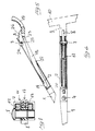
- Figure 1 is an exploded perspective view showing all the parts which make up the hinge and provide for its elastic features;
- Figure 2 is a partly sectional plan views of the hinge leg showing the elastic devices;
- Figure 3 is a plan view of the leg and hinge;
- Figure 4 is a side elevation view of the leg and hinge;
- Figure 5 is a partly sectional view showing this hinge in an extra opened position;
- Figure 6 is a partly sectional side elevation view of the hinge and leg;
- Figure 7 is a sectional view of the leg taken through the pivot point thereof;
- Figure 8 shows a modification of the elastic devices, as depicted in a sectional view through the leg and hinge;
- Figure 9 is a perspective view of the mushroom head shown in the embodiment of Figure 8;
- Figure 10 is a modified embodiment of the mushroom head related to plastic material eyeglasses frames;
- Figure 11 is an exploded view of a modified embodiment of the hinge according to the invention; and
- Figure 12 illustrates in section the assembling of the devices shown in Figure 11.
- Making reference to the drawing views, this invention may be seen to comprise a
leg 1 which is associated with ahollow metal pocket 2 having, in the embodiment of Figure 1, a substantially square cross-sectional configuration. - The two
parts nose 3 of theleg 1 into the hollow portion of thepocket element 2, followed by the insertion of a lock screw indicated at 4. - Said
hollow element 2 has, at the opposite end to the end connected to theleg 1, a round head 5, and in the proximities thereof, in the two horizontal cheeks, two holes indicated at 6 which allow ascrew 7 to be inserted forming the pivot element on amushroom head 8 which, in the instance of a metal eyeglasses frame, would be welded to a bracket-like body 9 attached to the frame 10 (Fig. 4). - Said
hollow element 2, which is conveniently formed from a metal material, has aside opening 11 formed in a wall thereof, and in the instance of Figure 1, arranged on the outward side of the leg to extend along the pocket element substantially over nearly one half its length from the rounded head 5. - Said opening 11 does not extend across the entire width of the wall but only the middle region thereof.
- Inserted into said
pocket 2, through the open side opposite to where theleg 1 has been previously mounted, are twolongitudinal plates opening 11. - The
plate 12 has a through hole, indicated at 14, intended to align with the hole 6, and theplate 13 has a corresponding threaded hole 15 wherein thescrew 7 is threaded which is also passed through thehole 16 formed in themushroom head 8. - Through the gap left between the two plates, 12 and 13, which corresponds, therefore, to the width of the
opening 11 as well as to the thickness of themushroom head 8, aleaf spring 17 is inserted which comprises three lozenge-shaped elements, a first thereof is indicated at 18 and identical to the others, said elements being obtained by stamping from a flexible metal foil material. - Said lozenge-shaped elements have one end, which will be that to be inserted into the pocket, formed with a
lug 19 which, on insertion of the element into the pocket, interlocks with a rectangular hole 20 (Figure 6) provided in the opposite wall of thepocket 2 to that having theopening 11. - At the middle region of the lozenge-
shaped element 18 is apivotal movement shoulder 21 which abuts theinside edge 22 of theopening 11 which will define the pivot point for theleaf spring 17. - The
opposite end 23 of heleaf spring 17 acts directly on all the substantially mutuallyorthogonal surfaces 24 and 25 (Figure 5) of themushroom head 8, to produce the elastic bias force. - As a direct extension of the
surface 25, there is arounded cutout 26 accommodating theend 23 to enable further rotation of theleg 1 and form the travel limit stop in the extra opened condition. - It should be noted that the
leaf spring 17 is inserted with the whole structure forming the hinge already assembled and the screws inserted, from the outside by pushing it into thepocket 2. - The operation of the hinge and related elastic device may be appreciated from the foregoing description and accompanying drawings.
- The
leaf spring 17 operates by deformation of two parts, one internal to the pocket and extending from thepivot point 21 to theinterlock point 19, and one external and extruding from thepivot point 21 to theend 23 acting on themushroom head 8. It will be apparent how the spring may be fabricated, by merely stamping it from a flexible steel sheet, and how the length of the lever arms extending from thepivot point 21 allows utilization of very low thrust forces on the mushroom head, owing to thesurface 25 forming with the hole center a relatively long lever arm, thereby the mushroom head may be extruded even from non-hard materials such as nickel silver or untreated steel. - The possibility of inserting the spring after the leg/hinge assembly has been assembled allows any types of treatment of the metal material which makes up the various parts without affecting the elastic properties of the leaf spring.
- The arrangement of the two
surfaces surface 24 and an opened position normal to the frame which corresponds to thesurface 25, while thecutout 26 enables an additional opening position with respect to the normal opened position and with spring return. - In a modified embodiment shown in Figures 8 and 9, the leaf spring, now indicated at 117, is arranged in a reverse position with respect to the former discussed hereinabove.
- More particularly, the
pocket element 102 has now theopening 111 on the inward side of the leg, now indicated at 101 and being connected to theelement 102 again through anose 103 inserted with alocking screw 104. - The
leaf spring 117 is quite identical to the one already discussed, whereas themushroom head 108 associated with thebracket element 109 is configured to be a mirror-image of the former, it still having two mutually orthogonal surfaces, respectively 125 and 124, which are acted upon by theend 123 of theleaf spring 117. - In this particular instance, it has been necessary to provide an unobstructed seat, indicated at 127, through which the
end 123 of theleaf spring 117 can be passed to move into a position of fully closed condition of theleg 101. - Where the eyeglasses frame is formed from a plastic material, the mushroom head should have the configuration shown in Figure 10, that is comprise a
shaped plate 201 which has its end on thepivoted side 202 provided with the two mutuallyorthogonal surfaces - Thus, there will occur a stepped down cross-section allowing an orthogonal bearing plate 204' to be inserted which permits the remaining portion to be embedded in the eyeglasses frame, there being again expediently provided a
hole 205 enabling the introduction of aretaining peg 206. - Illustrated in Figures 11 and 12 is a further embodiment of the invention hinge.
- In this embodiment, the leaf springs, now indicated at 301, are still lozenge-shaped and are used in a multiple set. Said springs have at one end a
recess 302 adapted to hook over ananchoring ridge 303 provided at one end of a stampedmetal leg 304. - The
springs 301 are, therefore, enclosed within ahinge body 305 machined from a metal section which is welded to theleg 304. -
Said body 305 has on the front two holes, one of which is shown and indicated at 306, which allows a pin, not shown, to be inserted therethrough which is also passed through ahole 307 provided in aplate 308 made rigid with abracket element 309 which is connected to thefront 310 of an eyeglasses frame. - Said
plate 308 also forms the cam whereon the end of thesprings 301 acts elastically. - In this embodiment, the
springs 301 are no longer exposed to view but rather fully contained within the eyeglasses legs, thus affording a greatly improved outward appearance. - This hinge, both as discussed in connection with its basic embodiment and variations, affords elasticity and an extra opened position both with metal frame and frames which are formed throughout or in part from plastic materials.
- The main advantages of the invention just described reside, on the one side, in that the various parts may be readily manufactured by merely stamping out metal plates, and in that the materials are not liable to develop problems from wear and may, accordingly, be less than specially hard and have untreated surfaces.
- An added advantage is that the length of the leaf spring affords, as mentioned, specific bias forces which are adequately weak with attendant low wear of the parts involved.
- A further important advantage is that the leaf spring can be inserted after all the other parts have been fully assembled and has been subjected to all of the processing steps envisaged.
- This affords a more economical manufacture and a finished product which has aesthetic characteristics far better, and costs much lower, than with the procedures followed heretofore.
- The faculty of providing the openings for the leaf springs either on the outward side or inward side relative to the leg also affords a high degree of design freedom to achieve unconditioned styling features.
- In practicing the invention, the materials and dimensions may be any selected ones to meet individual requirements.
Claims (10)
Priority Applications (1)
| Application Number | Priority Date | Filing Date | Title |
|---|---|---|---|
| AT84100812T ATE45047T1 (en) | 1983-02-04 | 1984-01-26 | SPRING HINGE FOR EYEGLASSES. |
Applications Claiming Priority (2)
| Application Number | Priority Date | Filing Date | Title |
|---|---|---|---|
| IT41521/83A IT1172735B (en) | 1983-02-04 | 1983-02-04 | ELASTIC HINGE FOR GLASSES |
| IT4152183 | 1983-02-04 |
Publications (3)
| Publication Number | Publication Date |
|---|---|
| EP0115826A2 EP0115826A2 (en) | 1984-08-15 |
| EP0115826A3 EP0115826A3 (en) | 1985-05-15 |
| EP0115826B1 true EP0115826B1 (en) | 1989-07-26 |
Family
ID=11250575
Family Applications (1)
| Application Number | Title | Priority Date | Filing Date |
|---|---|---|---|
| EP84100812A Expired EP0115826B1 (en) | 1983-02-04 | 1984-01-26 | Spring mount hinge for eyeglasses bows |
Country Status (11)
| Country | Link |
|---|---|
| US (1) | US4618226A (en) |
| EP (1) | EP0115826B1 (en) |
| JP (1) | JPS59148026A (en) |
| AT (1) | ATE45047T1 (en) |
| AU (1) | AU572817B2 (en) |
| CA (1) | CA1244686A (en) |
| DE (1) | DE3479162D1 (en) |
| ES (1) | ES277460Y (en) |
| IT (1) | IT1172735B (en) |
| PT (1) | PT78045B (en) |
| ZA (1) | ZA84333B (en) |
Cited By (2)
| Publication number | Priority date | Publication date | Assignee | Title |
|---|---|---|---|---|
| DE9005081U1 (en) * | 1990-05-04 | 1991-09-05 | Weber, Karl, 7000 Stuttgart, De | |
| WO2005081044A1 (en) * | 2004-02-19 | 2005-09-01 | Eye-Biz Pte Ltd | Spectacle frames |
Families Citing this family (36)
| Publication number | Priority date | Publication date | Assignee | Title |
|---|---|---|---|---|
| IT1187425B (en) * | 1985-07-05 | 1987-12-23 | Rino Sartor | GLASSES AUCTION |
| JPS61188120U (en) * | 1985-05-14 | 1986-11-22 | ||
| IT207535Z2 (en) * | 1986-03-03 | 1988-01-25 | Celes Optical | ELASTIC HINGE ADJUSTABLE PARTICULARLY FOR GLASSES. |
| JPS6345530U (en) * | 1986-09-12 | 1988-03-28 | ||
| IT1223738B (en) * | 1988-07-29 | 1990-09-29 | Fulvio Brucato | GLASSES |
| FR2626682B1 (en) * | 1989-01-31 | 1992-12-31 | Mugnier Marc | POSITIONING HINGES ADAPTED TO EYEWEAR MOUNTS |
| FR2651584B1 (en) * | 1989-09-07 | 1992-11-13 | Essilor Int | EYEWEAR MOUNT BRANCH WITH INTERCHANGEABLE BRANCH BODY. |
| FR2662516B1 (en) * | 1990-05-25 | 1993-08-20 | Chevassus | ELASTIC HINGE FOR GLASSES. |
| FR2665268B1 (en) * | 1990-07-27 | 1994-05-13 | Robert Sonthonnax | EYEWEAR MOUNT WITH ELASTIC HINGES. |
| US5258784A (en) * | 1991-07-17 | 1993-11-02 | Baines Ian J | Spectacle frame |
| US5835185A (en) * | 1993-09-10 | 1998-11-10 | Kallman; William R. | Spring-hinged frame for eyeware |
| US5455637A (en) * | 1993-09-10 | 1995-10-03 | Comdisco, Inc. | Electrochromic eyewear system, rechargeable eyewear and external charger therefor |
| US5455638A (en) * | 1993-09-10 | 1995-10-03 | Comdisco, Inc. | Electrochromic eyewear |
| US5900720A (en) * | 1993-09-10 | 1999-05-04 | Kallman; William R. | Micro-electronic power supply for electrochromic eyewear |
| US5657150A (en) * | 1993-09-10 | 1997-08-12 | Eyeonics Corporation | Electrochromic edge isolation-interconnect system, process, and device for its manufacture |
| US5666181A (en) * | 1996-04-11 | 1997-09-09 | Bausch & Lomb Incorporated | Spring temple for eyewear |
| FR2747482A1 (en) * | 1996-04-16 | 1997-10-17 | Vision Universelle Europ | Flexible joint for spectacle legs |
| FR2751762A1 (en) * | 1996-07-25 | 1998-01-30 | L Amy | Spring=loaded spectacle frame hinge |
| US5673095A (en) * | 1996-07-26 | 1997-09-30 | Bausch & Lomb Incorporated | Dual rate spring-action eyewear temple |
| FR2762348B1 (en) * | 1997-04-02 | 2000-03-03 | Richard Chene | EXTRA-FLAT EXTENSIBLE HINGE |
| JP2975361B1 (en) * | 1998-11-10 | 1999-11-10 | 株式会社タケダ企画 | Spring hinge for glasses |
| US6099117A (en) * | 1998-12-15 | 2000-08-08 | Ppg Industries Ohio, Inc. | Hinge with wire extending therethrough |
| FR2796731B1 (en) * | 1999-07-21 | 2001-09-14 | Nouvelle Idc Internat Design C | FLEXIBLE BRANCH DEVICE FOR EYEWEAR MOUNTING |
| US6196682B1 (en) | 1999-09-21 | 2001-03-06 | Steven Benjamin Walmsley | Clip-on eyewear with biased temple arms |
| US6163926A (en) * | 1999-11-12 | 2000-12-26 | Ppg Industries Ohio, Inc. | Split-pin hinge with wire extending therethrough |
| JP4471629B2 (en) | 2002-11-13 | 2010-06-02 | 花王株式会社 | Manufacturing method of parts for casting production |
| FR2864260B1 (en) * | 2003-12-17 | 2006-02-03 | Comotec | ELASTIC SHIELD OF EYEGLASS MOUNT, COMPRISING A LOW-SIZE ELASTIC RECALL MEMBER |
| DE102004054841B4 (en) * | 2004-04-16 | 2008-01-31 | Paris Frost | Elastic joint for glasses |
| JP3145561U (en) * | 2004-09-15 | 2008-10-16 | アイ−ビズ ピーティーイー リミテッド | Device for attaching spectacle frame and lens |
| ES2782350T3 (en) * | 2007-04-12 | 2020-09-14 | Killine Optical Ltd | Quick fixation for a spectacle temple |
| US8444265B2 (en) * | 2009-10-02 | 2013-05-21 | Oakley, Inc. | Eyeglass earstem with enhanced performance |
| ITTV20120133A1 (en) * | 2012-07-18 | 2014-01-19 | Ideal Srl | SPRING HINGE FOR GLASSES |
| ITUB20160923A1 (en) * | 2016-02-22 | 2017-08-22 | Safilo Sa Fabbrica Italiana Lavorazione Occhiali Spa | Spectacle frame |
| US10082677B2 (en) * | 2016-02-26 | 2018-09-25 | Four Nines Co., Ltd. | Eyeglass frame |
| US11714285B1 (en) | 2019-07-22 | 2023-08-01 | Apple Inc. | Head-mountable device with head securement mechanism |
| IT202100014378A1 (en) * | 2021-06-01 | 2022-12-01 | Wassa Optical Company Srls | Eyewear frame with hinge for quick assembly |
Family Cites Families (6)
| Publication number | Priority date | Publication date | Assignee | Title |
|---|---|---|---|---|
| US1599843A (en) * | 1925-03-30 | 1926-09-14 | American Optical Corp | Ophthalmic mounting |
| FR995032A (en) * | 1949-07-15 | 1951-11-26 | Joint for telescope arm | |
| FR1196398A (en) * | 1957-05-24 | 1959-11-24 | Leonardo Meccanoptica | Frame for glasses with snap-on temples by means of a flat spring |
| CH349425A (en) * | 1959-10-12 | 1960-10-15 | Rivo S A | Glasses frame |
| US3923384A (en) * | 1974-10-03 | 1975-12-02 | Foster Grant Co Inc | Self adjusting spectacle frame assembly |
| AU546755B2 (en) * | 1982-12-13 | 1985-09-19 | Safilo S.p.A. Societa: Azionaria Fabbrica Italiana Lavorazione Occhiali | Spectacle hinge |
-
1983
- 1983-02-04 IT IT41521/83A patent/IT1172735B/en active
-
1984
- 1984-01-17 ZA ZA84333A patent/ZA84333B/en unknown
- 1984-01-26 DE DE8484100812T patent/DE3479162D1/en not_active Expired
- 1984-01-26 EP EP84100812A patent/EP0115826B1/en not_active Expired
- 1984-01-26 AT AT84100812T patent/ATE45047T1/en not_active IP Right Cessation
- 1984-01-30 US US06/575,641 patent/US4618226A/en not_active Expired - Fee Related
- 1984-01-31 CA CA000446495A patent/CA1244686A/en not_active Expired
- 1984-02-01 AU AU23975/84A patent/AU572817B2/en not_active Ceased
- 1984-02-01 PT PT78045A patent/PT78045B/en not_active IP Right Cessation
- 1984-02-03 ES ES1984277460U patent/ES277460Y/en not_active Expired
- 1984-02-03 JP JP59018182A patent/JPS59148026A/en active Granted
Cited By (2)
| Publication number | Priority date | Publication date | Assignee | Title |
|---|---|---|---|---|
| DE9005081U1 (en) * | 1990-05-04 | 1991-09-05 | Weber, Karl, 7000 Stuttgart, De | |
| WO2005081044A1 (en) * | 2004-02-19 | 2005-09-01 | Eye-Biz Pte Ltd | Spectacle frames |
Also Published As
| Publication number | Publication date |
|---|---|
| AU572817B2 (en) | 1988-05-19 |
| IT8341521A0 (en) | 1983-02-04 |
| PT78045B (en) | 1986-04-17 |
| EP0115826A2 (en) | 1984-08-15 |
| EP0115826A3 (en) | 1985-05-15 |
| US4618226A (en) | 1986-10-21 |
| ES277460Y (en) | 1985-03-01 |
| JPH0531128B2 (en) | 1993-05-11 |
| JPS59148026A (en) | 1984-08-24 |
| AU2397584A (en) | 1984-08-09 |
| IT8341521A1 (en) | 1984-08-04 |
| ATE45047T1 (en) | 1989-08-15 |
| ZA84333B (en) | 1985-06-26 |
| IT1172735B (en) | 1987-06-18 |
| DE3479162D1 (en) | 1989-08-31 |
| PT78045A (en) | 1984-03-01 |
| ES277460U (en) | 1984-07-16 |
| CA1244686A (en) | 1988-11-15 |
Similar Documents
| Publication | Publication Date | Title |
|---|---|---|
| EP0115826B1 (en) | Spring mount hinge for eyeglasses bows | |
| JP2689282B2 (en) | Eyeglasses with spring hinges | |
| US5963296A (en) | Detachable cam-biased eyeglass temples | |
| US4780928A (en) | Spring biased hinge for spectacle frames | |
| EP0262099A2 (en) | A hinge for elastically articulating a leg to the face frame in optical frames | |
| CA2018533A1 (en) | Hinge structure, particularly for spectacle frames | |
| AT13927U2 (en) | Miniaturized elastic hinge, especially for spectacles | |
| US4222148A (en) | Spectacle hinge | |
| US3972090A (en) | Self-latching hinge | |
| US4499631A (en) | Furniture hinge permitting door opening angle of 110 degree or more | |
| US4617698A (en) | Spring-biased hinge assembly for spectacles | |
| US6019467A (en) | Hinge for temple and lens frame of eyeglasses | |
| US4790047A (en) | Hinge bushing adjustment means for a hinge assembly | |
| US4946268A (en) | Length-adjustable spectacle temple | |
| KR20040077418A (en) | Latch with switch | |
| US6587676B1 (en) | Hinge assembly | |
| US20080098574A1 (en) | Cord Lock | |
| EP0239011B1 (en) | Elastic hinge device for spectacle frames | |
| US4287641A (en) | Self-closing hinge | |
| US4884316A (en) | Hinge | |
| US4566160A (en) | End release inverse clevis buckle | |
| US4413385A (en) | Inverse clevis safety belt buckle | |
| JPH0424049Y2 (en) | ||
| JPH10331502A (en) | Automobile door checker | |
| US5013266A (en) | Twisted terminal for switching device |
Legal Events
| Date | Code | Title | Description |
|---|---|---|---|
| PUAI | Public reference made under article 153(3) epc to a published international application that has entered the european phase |
Free format text: ORIGINAL CODE: 0009012 |
|
| AK | Designated contracting states |
Designated state(s): AT BE CH DE FR GB LI NL SE |
|
| PUAL | Search report despatched |
Free format text: ORIGINAL CODE: 0009013 |
|
| AK | Designated contracting states |
Designated state(s): AT BE CH DE FR GB LI NL SE |
|
| 17P | Request for examination filed |
Effective date: 19851107 |
|
| 17Q | First examination report despatched |
Effective date: 19870304 |
|
| GRAA | (expected) grant |
Free format text: ORIGINAL CODE: 0009210 |
|
| AK | Designated contracting states |
Kind code of ref document: B1 Designated state(s): AT BE CH DE FR GB LI NL SE |
|
| PG25 | Lapsed in a contracting state [announced via postgrant information from national office to epo] |
Ref country code: NL Effective date: 19890726 Ref country code: BE Effective date: 19890726 Ref country code: AT Effective date: 19890726 |
|
| REF | Corresponds to: |
Ref document number: 45047 Country of ref document: AT Date of ref document: 19890815 Kind code of ref document: T |
|
| REF | Corresponds to: |
Ref document number: 3479162 Country of ref document: DE Date of ref document: 19890831 |
|
| ET | Fr: translation filed | ||
| PG25 | Lapsed in a contracting state [announced via postgrant information from national office to epo] |
Ref country code: SE Effective date: 19900101 |
|
| PLBE | No opposition filed within time limit |
Free format text: ORIGINAL CODE: 0009261 |
|
| STAA | Information on the status of an ep patent application or granted ep patent |
Free format text: STATUS: NO OPPOSITION FILED WITHIN TIME LIMIT |
|
| 26N | No opposition filed | ||
| PGFP | Annual fee paid to national office [announced via postgrant information from national office to epo] |
Ref country code: DE Payment date: 19971223 Year of fee payment: 15 |
|
| PGFP | Annual fee paid to national office [announced via postgrant information from national office to epo] |
Ref country code: CH Payment date: 19981221 Year of fee payment: 16 |
|
| PGFP | Annual fee paid to national office [announced via postgrant information from national office to epo] |
Ref country code: FR Payment date: 19981230 Year of fee payment: 16 |
|
| PGFP | Annual fee paid to national office [announced via postgrant information from national office to epo] |
Ref country code: GB Payment date: 19990115 Year of fee payment: 16 |
|
| PG25 | Lapsed in a contracting state [announced via postgrant information from national office to epo] |
Ref country code: DE Free format text: LAPSE BECAUSE OF NON-PAYMENT OF DUE FEES Effective date: 19991103 |
|
| PG25 | Lapsed in a contracting state [announced via postgrant information from national office to epo] |
Ref country code: GB Free format text: LAPSE BECAUSE OF NON-PAYMENT OF DUE FEES Effective date: 20000126 |
|
| PG25 | Lapsed in a contracting state [announced via postgrant information from national office to epo] |
Ref country code: LI Free format text: LAPSE BECAUSE OF NON-PAYMENT OF DUE FEES Effective date: 20000131 Ref country code: CH Free format text: LAPSE BECAUSE OF NON-PAYMENT OF DUE FEES Effective date: 20000131 |
|
| GBPC | Gb: european patent ceased through non-payment of renewal fee |
Effective date: 20000126 |
|
| REG | Reference to a national code |
Ref country code: CH Ref legal event code: PL |
|
| PG25 | Lapsed in a contracting state [announced via postgrant information from national office to epo] |
Ref country code: FR Free format text: LAPSE BECAUSE OF NON-PAYMENT OF DUE FEES Effective date: 20000929 |
|
| REG | Reference to a national code |
Ref country code: FR Ref legal event code: ST |