EP0114792B1 - Endermic injector device - Google Patents
Endermic injector device Download PDFInfo
- Publication number
- EP0114792B1 EP0114792B1 EP84830011A EP84830011A EP0114792B1 EP 0114792 B1 EP0114792 B1 EP 0114792B1 EP 84830011 A EP84830011 A EP 84830011A EP 84830011 A EP84830011 A EP 84830011A EP 0114792 B1 EP0114792 B1 EP 0114792B1
- Authority
- EP
- European Patent Office
- Prior art keywords
- injector device
- fluid
- phial
- valve
- shutter
- Prior art date
- Legal status (The legal status is an assumption and is not a legal conclusion. Google has not performed a legal analysis and makes no representation as to the accuracy of the status listed.)
- Expired
Links
- 239000012530 fluid Substances 0.000 claims description 19
- 238000002347 injection Methods 0.000 claims description 14
- 239000007924 injection Substances 0.000 claims description 14
- 238000006073 displacement reaction Methods 0.000 claims description 11
- 230000009471 action Effects 0.000 claims description 7
- 229910000831 Steel Inorganic materials 0.000 claims description 2
- 239000010959 steel Substances 0.000 claims description 2
- 239000007788 liquid Substances 0.000 description 18
- 239000003814 drug Substances 0.000 description 17
- 230000001105 regulatory effect Effects 0.000 description 8
- 238000005273 aeration Methods 0.000 description 4
- NOESYZHRGYRDHS-UHFFFAOYSA-N insulin Chemical compound N1C(=O)C(NC(=O)C(CCC(N)=O)NC(=O)C(CCC(O)=O)NC(=O)C(C(C)C)NC(=O)C(NC(=O)CN)C(C)CC)CSSCC(C(NC(CO)C(=O)NC(CC(C)C)C(=O)NC(CC=2C=CC(O)=CC=2)C(=O)NC(CCC(N)=O)C(=O)NC(CC(C)C)C(=O)NC(CCC(O)=O)C(=O)NC(CC(N)=O)C(=O)NC(CC=2C=CC(O)=CC=2)C(=O)NC(CSSCC(NC(=O)C(C(C)C)NC(=O)C(CC(C)C)NC(=O)C(CC=2C=CC(O)=CC=2)NC(=O)C(CC(C)C)NC(=O)C(C)NC(=O)C(CCC(O)=O)NC(=O)C(C(C)C)NC(=O)C(CC(C)C)NC(=O)C(CC=2NC=NC=2)NC(=O)C(CO)NC(=O)CNC2=O)C(=O)NCC(=O)NC(CCC(O)=O)C(=O)NC(CCCNC(N)=N)C(=O)NCC(=O)NC(CC=3C=CC=CC=3)C(=O)NC(CC=3C=CC=CC=3)C(=O)NC(CC=3C=CC(O)=CC=3)C(=O)NC(C(C)O)C(=O)N3C(CCC3)C(=O)NC(CCCCN)C(=O)NC(C)C(O)=O)C(=O)NC(CC(N)=O)C(O)=O)=O)NC(=O)C(C(C)CC)NC(=O)C(CO)NC(=O)C(C(C)O)NC(=O)C1CSSCC2NC(=O)C(CC(C)C)NC(=O)C(NC(=O)C(CCC(N)=O)NC(=O)C(CC(N)=O)NC(=O)C(NC(=O)C(N)CC=1C=CC=CC=1)C(C)C)CC1=CN=CN1 NOESYZHRGYRDHS-UHFFFAOYSA-N 0.000 description 4
- 238000012423 maintenance Methods 0.000 description 3
- 238000005259 measurement Methods 0.000 description 3
- 102000004877 Insulin Human genes 0.000 description 2
- 108090001061 Insulin Proteins 0.000 description 2
- 230000008901 benefit Effects 0.000 description 2
- 210000001520 comb Anatomy 0.000 description 2
- 238000004891 communication Methods 0.000 description 2
- 230000006835 compression Effects 0.000 description 2
- 238000007906 compression Methods 0.000 description 2
- 230000001143 conditioned effect Effects 0.000 description 2
- 230000003750 conditioning effect Effects 0.000 description 2
- 238000011109 contamination Methods 0.000 description 2
- 229940125396 insulin Drugs 0.000 description 2
- 238000012856 packing Methods 0.000 description 2
- 230000002093 peripheral effect Effects 0.000 description 2
- 230000001954 sterilising effect Effects 0.000 description 2
- 238000004659 sterilization and disinfection Methods 0.000 description 2
- 229910001369 Brass Inorganic materials 0.000 description 1
- 238000005452 bending Methods 0.000 description 1
- 239000010951 brass Substances 0.000 description 1
- 230000001276 controlling effect Effects 0.000 description 1
- 229920001971 elastomer Polymers 0.000 description 1
- 239000004615 ingredient Substances 0.000 description 1
- 238000003780 insertion Methods 0.000 description 1
- 230000037431 insertion Effects 0.000 description 1
- 238000012768 mass vaccination Methods 0.000 description 1
- 238000000034 method Methods 0.000 description 1
- 238000003801 milling Methods 0.000 description 1
- 239000000203 mixture Substances 0.000 description 1
- 238000012986 modification Methods 0.000 description 1
- 230000004048 modification Effects 0.000 description 1
- 230000035515 penetration Effects 0.000 description 1
- 230000000750 progressive effect Effects 0.000 description 1
- 230000000284 resting effect Effects 0.000 description 1
- 238000007789 sealing Methods 0.000 description 1
- 229920002379 silicone rubber Polymers 0.000 description 1
- 239000004945 silicone rubber Substances 0.000 description 1
- 238000001356 surgical procedure Methods 0.000 description 1
Images


Classifications
-
- A—HUMAN NECESSITIES
- A61—MEDICAL OR VETERINARY SCIENCE; HYGIENE
- A61M—DEVICES FOR INTRODUCING MEDIA INTO, OR ONTO, THE BODY; DEVICES FOR TRANSDUCING BODY MEDIA OR FOR TAKING MEDIA FROM THE BODY; DEVICES FOR PRODUCING OR ENDING SLEEP OR STUPOR
- A61M5/00—Devices for bringing media into the body in a subcutaneous, intra-vascular or intramuscular way; Accessories therefor, e.g. filling or cleaning devices, arm-rests
- A61M5/178—Syringes
- A61M5/30—Syringes for injection by jet action, without needle, e.g. for use with replaceable ampoules or carpules
-
- A—HUMAN NECESSITIES
- A61—MEDICAL OR VETERINARY SCIENCE; HYGIENE
- A61M—DEVICES FOR INTRODUCING MEDIA INTO, OR ONTO, THE BODY; DEVICES FOR TRANSDUCING BODY MEDIA OR FOR TAKING MEDIA FROM THE BODY; DEVICES FOR PRODUCING OR ENDING SLEEP OR STUPOR
- A61M5/00—Devices for bringing media into the body in a subcutaneous, intra-vascular or intramuscular way; Accessories therefor, e.g. filling or cleaning devices, arm-rests
- A61M5/178—Syringes
- A61M5/19—Syringes having more than one chamber, e.g. including a manifold coupling two parallelly aligned syringes through separate channels to a common discharge assembly
-
- A—HUMAN NECESSITIES
- A61—MEDICAL OR VETERINARY SCIENCE; HYGIENE
- A61M—DEVICES FOR INTRODUCING MEDIA INTO, OR ONTO, THE BODY; DEVICES FOR TRANSDUCING BODY MEDIA OR FOR TAKING MEDIA FROM THE BODY; DEVICES FOR PRODUCING OR ENDING SLEEP OR STUPOR
- A61M5/00—Devices for bringing media into the body in a subcutaneous, intra-vascular or intramuscular way; Accessories therefor, e.g. filling or cleaning devices, arm-rests
- A61M5/178—Syringes
- A61M5/20—Automatic syringes, e.g. with automatically actuated piston rod, with automatic needle injection, filling automatically
- A61M5/204—Automatic syringes, e.g. with automatically actuated piston rod, with automatic needle injection, filling automatically connected to external reservoirs for multiple refilling
-
- A—HUMAN NECESSITIES
- A61—MEDICAL OR VETERINARY SCIENCE; HYGIENE
- A61M—DEVICES FOR INTRODUCING MEDIA INTO, OR ONTO, THE BODY; DEVICES FOR TRANSDUCING BODY MEDIA OR FOR TAKING MEDIA FROM THE BODY; DEVICES FOR PRODUCING OR ENDING SLEEP OR STUPOR
- A61M5/00—Devices for bringing media into the body in a subcutaneous, intra-vascular or intramuscular way; Accessories therefor, e.g. filling or cleaning devices, arm-rests
- A61M5/178—Syringes
- A61M5/20—Automatic syringes, e.g. with automatically actuated piston rod, with automatic needle injection, filling automatically
- A61M5/2066—Automatic syringes, e.g. with automatically actuated piston rod, with automatic needle injection, filling automatically comprising means for injection of two or more media, e.g. by mixing
Definitions
- US-A-2,737,946 too concerns an injector having a very complicated structure.
- the medicament is held in a special phial, which is inserted near the head of the injector at the time when it is to be used.
- This apparatus has a very heavy, complex structure and also comprises a very complicated system for fitting and positioning the phial, thereby entailing overall some considerable handling difficulties.
- the phial itself is hardly protected at all and is subject to breakage, a fact which restricts the ability to carry the device from place to place by hand or on the person..'
- a noteworthy shortcoming of said device is the presence of an air filter fitted near the container of the phial, this filter being needed to maintain the required pressure within the phial itself during the loading of the medicinal and also to maintain sterile conditions within the phial itself.
- the known device provides difficulties in dismantling for sterilization and maintenance and needs service keys, but the head of the piston can be easily dismantled as it is clamped to the piston by means of a resiliently expandable ring.
- a further drawback lies in the fact that, if the valve is ever left inadvertently in the drawing position, the phial may explode when the apparatus is operated. Besides, after being operated, the device has to be fully unloaded before it can be recharged.
- US-A-3,908,651 proposes an. injector which enables the dose to be measured and the medicament to be loaded from the outside and to be drawn from normal, commercially available phials.
- This apparatus has an injecting head with a complex structure and with a safety device that hinders the return of the medicament into the phial in the case of wrong usage.
- a further drawback lies in the fact that the device needs service keys when it has to be dismantled.
- Another purpose of the invention is to provide an endermic injector device which can be used readily and at once and of which the need for maintenance can be substantially overlooked.
- a further purpose of the invention is to provide an injector of a relatively simple structure, easy to dismantle and to sterilize and provided with an outstanding degree of safety against wrong usage.
- said valve has at least three positions, of which one allows the loaded liquid to be expelled, whereas the other two enable liquid to be aspirated from one or the other of said two phials, as desired, and the quantities to be measured from them in sequence.
- Said spring means can be pre-loaded to the required value so as to supply the desired injection pressure and can be pre-loaded in steps or continuously.
- the attached tables contain the following:-
- the central body 11 can have ridges or milling so as to be easier to grip.
- Each socket 214 has within it an aeration needle 16 and a needle 17 to draw liquid.
- the invention envisages the ability to close with said plug the front part of the head 12 where the nozzle means 18 are located, thus isolating the head 12 from the environment.
- the invention likewise envisages the ability to plug the phial receiving sockets 214 with suitable plugs (not shown) when the device is not in use and phials 15 are not fitted to the connector 114.
- the connector 114 is secured to the valve body 119 with at least locking pin means 59 inserted under pressure in a hole 159 in our example.
- the reciprocal axial positions of the head 12 and body 11 can be regulated advantageously so as to enable the working pressure to be regulated; said regulation can be obtained in ways which we shall describe hereinafter.
- the regulation can be envisaged as being obtained in steps or continuously.
- the loading and tripping means 20 constitute a group to control aspiration and expulsion and comprise a rotatable cover 22, with a crank 23, from which a trigger 24 protrudes so as to trip the device as soon as the latter has been filled.
- crank 23 is pivoted at 123 so that it can be folded back, as shown in Fig. 1a, when the device is not in use.
- the measurement means 21 have on their outside a ring 25 which is preferably milled. Said ring 25 can be rotated and is towed periodically by the rotation of the rotatable cover 22 according to a ratio which is suitably pre-set.
- the connector 114 In the upper part of the head 12 there is the connector 114, of which it is possible to see one phial receiving socket 214 with needles 16 and 17.
- each socket 214 gets air from a conduit 116 which communicates with the outside and which is opened and closed by the shutter 31 of the valve 19, which in our example can slide axially within the valve body 119.
- the shutter 31 will comprise advantageously circumferential sealing grooves 62.
- These grooves 62 which can be seen in Figs. 3a and 3b, where they are drawn with thin lines, have a depth of about some hundredths of a millimetre and create a labyrinth seal, thus not requiring rubber packings, which deteriorate readily, on the shutter 31.
- An alignment head means 32 (Fig. 4b) with fins' 132 is able to slide axially on the valve body 119 and, by cooperating with the side notches 45 in the shutter 31, serves to ensure the right positioning of said shutter 31 during ejection of the liquid (thus preventing wrong usage during the ejection, as will become clear hereinafter) and also to ensure the right positioning of the shutter 31 in its two end positions during filling of fluid.
- An extension 219 which is located behind the valve body 119 accommodates a cylindrical chamber 33, wherein a small piston 34 which can move axially cooperates.
- the small piston 34 is located at the end of a plunger 35, which in its turn can slide in a chamber 135.
- All the rear part 219 of the valve body 119 is contained within a sleeve 112 fixed within the body 11.
- valve body 119 can be readily connected to and disconnected from said sleeve 112 by means of a bayonet fitting 319 tocated in the rear extension 219 and cooperating with a suitable seating in said sleeve 112.
- Fig. 2b shows the propulsion and regulation group 28, which comprises the regulation subgroup 60.
- the chamber 135 also lodges spring means 52, which may consist of one or more compression springs.
- spring means 52 comprise sets of springs 152 and 252 which are shown as being located one within the other.
- Guide shafts 352 prevent sideways bending of the springs 152-252 during the cocking and loading phase and thus enable the axial thrust of said springs to be exploited to the utmost.
- springs 52 rather than a compressed gas eliminates not only the difficulties connected with the employment of seals between the various parts but also all problems arising from the employment of gas under pressure.
- the prong 211 When the elastic tongue 111 is raised, the prong 211 is disengaged from the hollow 212 and permits rotation of the sleeve 112, which can be thus rotated as desired by being screwed up or unscrewed.
- the system shown which envisages one or more hollows 212, enables regulation to be carried out in steps.
- This group constitutes the means 60 for regulating the pre-loading of the spring means 52.
- Reference means 56 consisting of notches or marks or any desired sign make it possible to check visually the axial position of the sleeve 112 in relation to the body 11 and thus the value of the pre-loading of the springs.
- the plunger35 is made to go backwards and compresses the springs 52 by means of the collar 235 against which the springs 52 thrust and to which the guide shafts 352 are solidly fixed in our example.
- Said backward movement of the plunger 35 is caused by the action of two or more comb-wise means 36, which consist of threaded half-rings or segments of rings on the threaded stub end 335.
- Said comb-wise means 36 are lodged and radially guided within grooves on the sides of a sleeve 37, which is solidly fixed to the cover 22 and revolvably anchored to the body 11 by means of the bearing 137 and ridge 237 in our example.
- said sleeve 37 is embodied with two counterpart halves so that it can be fitted to the body 11.
- the actuation means 40 being actuated by the trigger 24 and resting on the pressure ring 122, thrusts the cup means 38 forwards and overcomes the elastic action of the spring 39.
- the tooth 138 begins to cooperate with the bevel 136; the comb means 36 are freed thereby and can move backwards in a radial direction within the cup means 38 owing to the inner diameter of the cup means 38 being greater than that of the end portion 138 thereof, and thus become disengaged from the screw threads of the stub end 335.
- the stub end 335 being thus disengaged from the comb means 36 and freed from said conditioning, is thrust forwards by the springs 52 acting on the collar 235.
- a steel wire 58 drawn by the sleeve 37, runs between the cam 41 and ring 25. Said wire 58 is lodged partly in the sleeve 37 within a peripheral lengthwise seating 158 and is solidly fixed circumferentially to the sleeve 37 itself.
- the ring 25 carries out a number of clicks determined by the number of the ridges 141 and also carries out, for each click, a forward movement determined by the circumferential extent of the ridge 141.
- the clicks are fixed momentarily by notch means 61 or hollows made in the ring 25 and cooperating with spring means (tongue-wise, spring with ball, etc.) located in the sleeve 26.
- the number of clicks can be read on the numbered scale 125 through the window 126 (Fig. 1b) and in this way the quantity of the dose loaded can be determined.
- the valve 119 works as follows: the shutter 31 (Fig. 4) can be moved sideways to one side or the other to select the phial from which it is wished to draw the liquid. In this way one or the other of two filling holes 42 is placed so as to coincide with the relative channel 117 of the valve 19.
- the form of the holes 42 (see Fig. 4) is such that in each of the two sideways positions of the shutter 31 said holes 42 put the relative filling channel 117 into communication with that tract of the central channel 43 of the valve body 119 which is oriented towards the chamber 33 with which it communicates.
- aeration holes 44 are made to coincide with the aeration channels 116, which are thus open and communicate with the outside after the fitting of suitable filter means.
- the shutter 31 can take up, as wished, the partly axially displaced two side positions (Fig. 4b - see the line of dashes 31A) while the head 32 is in the fully outward position 32A.
- the fins 132 delimit sideways axial deviation, and the shutter 31 puts the holes 42-44 in positions 42A and 44A so that said holes 42-44 are ready for the operations of charging fluid from the phials 15 and of sending air into said phials 15.
- Fig. 6 shows a detail of the small piston 34.
- a stub 134 with an elastic ring 234 is inserted within the head 35A of the plunger 35.
- the elastic ring 234 is engaged in an appropriate circumferential seating 53 located in the head 35A and permits ready attachment and removal of the small piston 34, which in this way can be speedily replaced.
- the head 334 of the small piston 34 of our example comprises a brass ring 47, an 0-ring 48 with outer ring 49 and a frontal ring 50 connected to the pin 51 by caulking 151.
- the plunger 35 goes backward initially without drawing the small piston 34, until the bevelled surface 153 of the seating 53 engages the ring 234.
- the device of the invention works in the following way:
- the sum of the quantities of liquid aspirated from the first and second phials 15 is read in the window 126.
- the stub end 335 is therefore disengaged therefrom and the plunger 35, being thrust by the springs, pushes the small piston 34 back into the chamber 33.
- the liquid is ejected thereby at the desired pressure through the central channel 43 and nozzle 118.
Landscapes
- Health & Medical Sciences (AREA)
- Vascular Medicine (AREA)
- Engineering & Computer Science (AREA)
- Anesthesiology (AREA)
- Biomedical Technology (AREA)
- Heart & Thoracic Surgery (AREA)
- Hematology (AREA)
- Life Sciences & Earth Sciences (AREA)
- Animal Behavior & Ethology (AREA)
- General Health & Medical Sciences (AREA)
- Public Health (AREA)
- Veterinary Medicine (AREA)
- Infusion, Injection, And Reservoir Apparatuses (AREA)
- Measuring Pulse, Heart Rate, Blood Pressure Or Blood Flow (AREA)
- Surgical Instruments (AREA)
- Processing Of Meat And Fish (AREA)
- Threshing Machine Elements (AREA)
- Catching Or Destruction (AREA)
Abstract
Description
- This invention concerns an endermic injector device. To be more exact, the invention concerns an endermic injector able to carry out intra- cutaneous injection of liquids without a needle by means of a jet of fluid under high pressure.
- The injector of the invention makes it possible to regulate the dose of the liquid to be injected and also makes it possible to regulate the possible dosing and mixture of two or more liquids and is particularly suitable for injections of insulin although it is not restricted thereto.
- Indeed, the use of two or more different qualities of insulin for suitable mixing is often required for such injections.
- The known art envisages various endermic injection devices, but they all entail many drawbacks.
- US-A-2,717,597 shows an injector apparatus with a very complicated structure. Said injector comprises in the zone of its head a chamber for lodging a special phial containing the medicament.
- This apparatus involves considerable difficulties during loading since it cannot be loaded from outside but has to be partly dismantled for insertion of said phial for each injection.
- Said apparatus also has an inadequate safety system and is not completely hygienic, besides not allowing the medicament to be drawn from the normal phials.commercially available.
- Moreover, with this device the dose injected is fixed or else, if it is wished to vary the dose, it is necessary to use phials of differing capacities.
- US-A-2,737,946 too concerns an injector having a very complicated structure. In this case also the medicament is held in a special phial, which is inserted near the head of the injector at the time when it is to be used.
- This known device, like the one before it, does not allow the medicament to be loaded from the outside with the normal, commercially available phials nor does it allow every desired dose to be administered.
- Furthermore, the pressure which thrusts the medicament through the small outlet hole is generated by a gas which is compressed beforehand during loading and which is held momentarily in a chamber within said apparatus. The high pressures to which the gas has to be compressed entail difficulties in providing a gastight seal and prejudice the working life of the apparatus itself.
- US-A-2,928,390 envisages an injector device which enables the medicament to be loaded and the dose to be regulated from the outside and to be drawn from normal, commercially available phials.
- Said device works in two stages, of which the first and speedier stage enables the medicament to overcome the compactness of the skin, whereas the next and slower stage permits excellent penetration by the medicament.
- This device has an outstandingly complex structure, which makes it heavy, hard to handle and very costly; moreover, sterilization and maintenance of the device are a great problem.
- The loading of the springs which provide the thrust for the cylinders that generate the outlet pressure of the medicament is also carried out with compressed air. This involves a considerable drawback as the injections can only be administered when an independent means to compress air is available.
- The device disclosed in US-A-3,330,276 enables the dose to be regulated and the medicament to be loaded from outside and to be drawn from normal, commercially available phials.
- This apparatus has a very heavy, complex structure and also comprises a very complicated system for fitting and positioning the phial, thereby entailing overall some considerable handling difficulties.
- Moreover, the phial itself is hardly protected at all and is subject to breakage, a fact which restricts the ability to carry the device from place to place by hand or on the person..'
- Furthermore, with such a device only one type of medicinal can be loaded at a time; this factor limits its use since some patients such as diabetics, for instance, need injections of which the components are drawn from different phials and mixed advantageously before being injected.
- In said known device the thrust applied by the elastic means to expel the medicament may not be strong enough, above all because of the complexity and weight of the parts of which the device consists.
- The power of the means that propels the medicament can be regulated by the reciprocal action of two sleeves, of which one can be screwed onto the other.
- Moreover, a noteworthy shortcoming of said device is the presence of an air filter fitted near the container of the phial, this filter being needed to maintain the required pressure within the phial itself during the loading of the medicinal and also to maintain sterile conditions within the phial itself.
- Moreover, the known device provides difficulties in dismantling for sterilization and maintenance and needs service keys, but the head of the piston can be easily dismantled as it is clamped to the piston by means of a resiliently expandable ring.
- A further drawback lies in the fact that, if the valve is ever left inadvertently in the drawing position, the phial may explode when the apparatus is operated. Besides, after being operated, the device has to be fully unloaded before it can be recharged.
- US-A-3,330,277 proposes a variant of 3,330,276 but without applying any substantial functional modifications or improvements thereto.
- US-A-3,526,225 discloses an injector device for use in conjunction with an outside source of compressed air. The known device is therefore suitable only for use in a surgery (mass vaccinations). Moreover, it does not envisage the possibility of mixing ingredients but does arrange for a possible regulation of the preloading.
- US-A-3,714,943 concerns a device able to accommodate within itself a plurality of special phials of which the contents can be injected one by one, but in this case too it is not possible to use the normal, commercially available phials and to load the medicament from the outside.
- Moreover, the pressure needed to expel the medicament is generated with a gas compressed beforehand in a chamber within the device itself. This leads to problems of a gastight seal, as we said earlier.
- US-A-3,827,601 proposes a device using manual compression of a low power and is not relevant for the purposes of this invention.
- US-A-3,908,651 proposes an. injector which enables the dose to be measured and the medicament to be loaded from the outside and to be drawn from normal, commercially available phials.
- This apparatus has an injecting head with a complex structure and with a safety device that hinders the return of the medicament into the phial in the case of wrong usage.
- The device comprises also:
- - an aspiration and ejection means with valve means to draw and deliver fluid, a cylindrical chamber to contain fluid together with a removable small piston and ejection nozzle,
- - means to control aspiration and expulsion which includes means for axial rearward displacement of said piston, spring means for the forward axial displacement of said piston and tripping means for releasing the piston under the action of the spring means,
- - means to hold and position a phial, said means comprising one phial receiving socket including two needles cooperating with the valve means for temporary connection to the cylindrical chamber and to the exterior, said valve means comprising a shutter able to take up an injection position and a specific filling position for the phial receiving socket, and
- - means to regulate the pre-loading of spring means.
- Said device also comprises a very complicated fixture system and is suitable for administering the medicament from only one phial at a time, a fact which is a great drawback, as we said earlier. Moreover, the patent does not show how the injecting action is obtained, graduated and developed.
- A further drawback lies in the fact that the device needs service keys when it has to be dismantled.
- Our invention tends to overcome the drawbacks of the known art and provides many benefits and advantages.
- Thus it is a purpose of the invention to provide an injector which makes possible a speedy and desired measured loading of the components to be injected during the filling stage.
- It is also a purpose of the invention to enable two or more liquids to be loaded in measured quantities in sequence and to be mixed, also during the filling stage.
- Another purpose of the invention is to provide an endermic injector device which can be used readily and at once and of which the need for maintenance can be substantially overlooked. A further purpose of the invention is to provide an injector of a relatively simple structure, easy to dismantle and to sterilize and provided with an outstanding degree of safety against wrong usage.
- According to the invention it is possible to select aspiration from two or more commercially available phials suitably connected to the device, by pre-setting an appropriate valve.
- In the case of two phials said valve has at least three positions, of which one allows the loaded liquid to be expelled, whereas the other two enable liquid to be aspirated from one or the other of said two phials, as desired, and the quantities to be measured from them in sequence.
- According to the invention the injector device is equipped with dosage indicator means able to show the quantity of liquid aspirated from time to time during filling.
- Filling takes place simply by means of negative pressure through the use of piston means drawn backwards with screw means, thereby overcoming the resistance of contrast spring means. Said spring means can be pre-loaded to the required value so as to supply the desired injection pressure and can be pre-loaded in steps or continuously.
- Actuation of a trigger means makes possible the speedy disengagement of the piston, which is thrust quickly forward by the spring means into the chamber where there is the loaded fluid, with a resultant creation of the desired pressure in said frontal chamber holding said piston. Said pressure causes the discharge, through a nozzle, of the fluid held in said frontal chamber in the form of a jet under high pressure.
- The invention is therefore embodied with an endermic injector device for making intra- cutaneous injections without a needle, which is suitable to inject under pressure at least one fluid drawn in a measured dose from replaceable phials and comprises in cooperation:
- - an aspiration and ejection means with valve means to draw and deliver fluid, a cylindrical chamber to contain fluid together with a removable small piston and ejection nozzle,
- - a means to control aspiration and expulsion which includes means for axial rearward displacement of said piston, spring means for the forward axial displacement of said piston and tripping means for releasing the piston under the action of the spring means,
- - means to hold and position a phial, said means comprising one phial receiving socket including two needles cooperating with the valve means for temporary connection to the cylindrical chamber and to the exterior, said valve means comprising a shutter able to take up an injection position and a specific filling position for the phial receiving socket, and
- - means to regulate the pre-loading of spring means, the device being characterized in that:
- - the means to hold and position phials comprises two phial receiving sockets, each of which includes two separate needles,
- - and in that there are provided safety means with an alignment head sliding axially on the valve means, said safety means ensuring the correct position of the shutter during aspiration and ejection of the fluid to be injected, and
- - means for displaying the quantity of the doses to be injected.
- We shall describe hereinafter, as a non-restrictive example, a preferred embodiment of the device of the invention.
- The attached tables contain the following:-
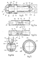
- Fig. 1a shows a three-dimensional view of the device of the invention;
- Fig. 1 b shows a side view of the device of Fig. 1a;
- Fig. 2a shows a section of the zone of the chamber of the fluid and of the injector zone;
- Fig. 2b shows a section of the zone of the contrast spring;
- Fig. 2c shows a section of the loading and tripping zone;
- Figs. 3a and 3b give two views, at right angles to each other, of the shutter of the valve;
- Fig. 4a shows a section of the seating of the shutter of Fig. 3 in the body of the valve;
- Fig. 4b shows the interacting working of the valve and of the alignment and safety head;
- Fig. 5 shows the graduated crown with the flange;
- Fig. 6 shows a preferred conformation of the small piston.
- In the figures, 10 is the endermic injector of the invention. Outwardly the
injector 10 consists substantially of acentral body 11 of a substantially and advantageously cylindrical or prismatic shape, to which ahead 12 andrear part 13 are connected. - The
central body 11 can have ridges or milling so as to be easier to grip. - The
head 12 comprises means 14 to fix andsupport phials 15 which can be perforated and of which in our example two can be inserted. - Said means 14 to fix phials consist, in this instance, of a
connector 114 with twophial receiving sockets 214, one on each side; when twophials 15 are envisaged, there is one socket for each phial. - Each
socket 214 has within it anaeration needle 16 and aneedle 17 to draw liquid. - On the
connector 114 means 57 are envisaged for fixture of a plug to protect the nozzle (not shown here) when the device is not in use. - Said means 57 to fix a plug to protect the nozzle have the purpose of preventing said plug from being rested on outside surfaces with the danger of contamination by microbes.
- Indeed, the invention envisages the ability to close with said plug the front part of the
head 12 where the nozzle means 18 are located, thus isolating thehead 12 from the environment. - For the same reason the invention likewise envisages the ability to plug the
phial receiving sockets 214 with suitable plugs (not shown) when the device is not in use andphials 15 are not fitted to theconnector 114. - The
connector 114 is secured to thevalve body 119 with at least locking pin means 59 inserted under pressure in ahole 159 in our example. - The
head 12 also comprises nozzle means 18 and valve means 19. The functions of said valve means 19 will be detailed in the description hereinafter. - The reciprocal axial positions of the
head 12 andbody 11 can be regulated advantageously so as to enable the working pressure to be regulated; said regulation can be obtained in ways which we shall describe hereinafter. The regulation can be envisaged as being obtained in steps or continuously. - The
rear part 13 includes loading and trippingmeans 20 and means 21 for measuring or displaying the doses. - Outwardly the loading and tripping
means 20 constitute a group to control aspiration and expulsion and comprise arotatable cover 22, with acrank 23, from which atrigger 24 protrudes so as to trip the device as soon as the latter has been filled. - The
crank 23 is pivoted at 123 so that it can be folded back, as shown in Fig. 1a, when the device is not in use. - The measurement means 21 have on their outside a
ring 25 which is preferably milled. Saidring 25 can be rotated and is towed periodically by the rotation of therotatable cover 22 according to a ratio which is suitably pre-set. - The
ring 25 bears a numberedscale 125 of which the indications can be seen through thewindow 126 in theimmovable sleeve 26 solidly fixed to thebody 11. - From a working point of view the
device 10 can be deemed to consist of four sections (Figs. 2) or working groups cooperating closely with each other:- - a) an aspiration and
ejection group 27 whither the fluid is aspirated and whence it is ejected at the required pressure; - b) a propulsion and pressure-
regulation group 28 comprising the means which generate and regulate the pressure required; - c) loading group or group to control aspiration and
expulsion 29, which comprises means to cock the means which generate the ejection pressure; - d) measurement group or means to display quantity of
dose 30, which comprises the means able to make it possible to control the dose being loaded. - Fig. 2a shows a section of part of the
body 11 and of thewhole head 12, that is to say, it is possible to see both the aspiration andejection group 27 and thepart 60 regulating pressure in thegroup 28. - In the upper part of the
head 12 there is theconnector 114, of which it is possible to see onephial receiving socket 214 withneedles - The
needle 16 of eachsocket 214 gets air from aconduit 116 which communicates with the outside and which is opened and closed by theshutter 31 of thevalve 19, which in our example can slide axially within thevalve body 119. - According to the invention the
shutter 31 will comprise advantageously circumferential sealinggrooves 62. Thesegrooves 62, which can be seen in Figs. 3a and 3b, where they are drawn with thin lines, have a depth of about some hundredths of a millimetre and create a labyrinth seal, thus not requiring rubber packings, which deteriorate readily, on theshutter 31. - The
needles socket 214 are inserted with force into the respective channels 116-117 within thevalve body 119 so as to ensure a hydraulic seal. - A packing 314, which is made preferably of silicone rubber, is positioned between the
valve body 119 andconnector 114 and improves this seal by preventing any possible inflow of air or loss of fluid and therefore any danger of contamination. - The nozzle means 18 consist of a
nozzle 118 which can be screwed onto the front of thevalve body 119. - An alignment head means 32 (Fig. 4b) with fins' 132 is able to slide axially on the
valve body 119 and, by cooperating with theside notches 45 in theshutter 31, serves to ensure the right positioning of saidshutter 31 during ejection of the liquid (thus preventing wrong usage during the ejection, as will become clear hereinafter) and also to ensure the right positioning of theshutter 31 in its two end positions during filling of fluid. - An
extension 219 which is located behind thevalve body 119 accommodates acylindrical chamber 33, wherein asmall piston 34 which can move axially cooperates. - The
small piston 34 is located at the end of aplunger 35, which in its turn can slide in achamber 135. - This part of the
head 12 forms the aspiration andejection group 27. - All the
rear part 219 of thevalve body 119 is contained within asleeve 112 fixed within thebody 11. - The
valve body 119 can be readily connected to and disconnected from saidsleeve 112 by means of a bayonet fitting 319 tocated in therear extension 219 and cooperating with a suitable seating in saidsleeve 112. - Fig. 2b shows the propulsion and
regulation group 28, which comprises theregulation subgroup 60. - In this figure the
chamber 135 also lodges spring means 52, which may consist of one or more compression springs. In the example shown the spring means 52 comprise sets ofsprings - The employment of a double set of spring means makes possible an ejecting characteristic consisting of initially very great pressure so as to overcome the resistance of the skin, said pressure lessening thereafter so as to provide a gradual injection of liquid.
-
Guide shafts 352 prevent sideways bending of the springs 152-252 during the cocking and loading phase and thus enable the axial thrust of said springs to be exploited to the utmost. - The use of
springs 52 rather than a compressed gas eliminates not only the difficulties connected with the employment of seals between the various parts but also all problems arising from the employment of gas under pressure. - So as to permit the pressure to be regulated, it is possible to regulate the pre-loading of the springs by altering the axial position of the
sleeve 112 which lodges theextension 119, and thus to use the group, or means, which regulates pre-loading orpressure 60. - In our example this axial positioning is obtained momentarily with a tongue 111 (Fig. 1a) bearing a
prong 211 which is engaged, through ahole 311 in thebody 11, in a hollow 212 made axially and peripherally in thesleeve 112. - When the
elastic tongue 111 is raised, theprong 211 is disengaged from the hollow 212 and permits rotation of thesleeve 112, which can be thus rotated as desired by being screwed up or unscrewed. - After each full revolution or desired portion of a revolution the
sleeve 112 is clamped again by theprong 211. - The system shown, which envisages one or
more hollows 212, enables regulation to be carried out in steps. This group constitutes themeans 60 for regulating the pre-loading of the spring means 52. - Reference means 56 consisting of notches or marks or any desired sign make it possible to check visually the axial position of the
sleeve 112 in relation to thebody 11 and thus the value of the pre-loading of the springs. - With the help of the loading group or group controlling aspiration and
expulsion 29,the plunger35 is made to go backwards and compresses thesprings 52 by means of thecollar 235 against which thesprings 52 thrust and to which theguide shafts 352 are solidly fixed in our example. - Said backward movement of the
plunger 35 is caused by the action of two or more comb-wise means 36, which consist of threaded half-rings or segments of rings on the threadedstub end 335. - Said comb-wise means 36 are lodged and radially guided within grooves on the sides of a
sleeve 37, which is solidly fixed to thecover 22 and revolvably anchored to thebody 11 by means of thebearing 137 andridge 237 in our example. - In the lay-out shown said
sleeve 37 is embodied with two counterpart halves so that it can be fitted to thebody 11. - The annular
circumferential ridge 237 cooperates with a suitable circumferential groove and thus hinders axial sliding of thesleeve 37 in relation to thebody 11 itself but permits circumferential rotation of saidsleeve 37. - A cup means 38 keeps the comb means 36 in position and conditions them. The
spring 39 normally keeps thesleeve 37 and cup means 38 apart. - The actuation means 40, being actuated by the
trigger 24 and resting on thepressure ring 122, thrusts the cup means 38 forwards and overcomes the elastic action of thespring 39. - The mutual cooperation of the
forward end tooth 138 and thefront bevel 136 of the comb means 36 creates the required conditioning. - Displacing the cup means 38 forwards, the
tooth 138 begins to cooperate with thebevel 136; the comb means 36 are freed thereby and can move backwards in a radial direction within the cup means 38 owing to the inner diameter of the cup means 38 being greater than that of theend portion 138 thereof, and thus become disengaged from the screw threads of thestub end 335. - The
stub end 335, being thus disengaged from the comb means 36 and freed from said conditioning, is thrust forwards by thesprings 52 acting on thecollar 235. - The
measurement group 30 comprises an immovable cam 41 (Fig. 5) coaxial with thering 25 and secured to thecentral body 11. - A
steel wire 58, drawn by thesleeve 37, runs between thecam 41 andring 25. Saidwire 58 is lodged partly in thesleeve 37 within a peripherallengthwise seating 158 and is solidly fixed circumferentially to thesleeve 37 itself. - When the
wire 58 meets aridge 141, it moves radially outwards in our example and engages anotch 225, thus pulling thering 25 through a number of clicks determined by the circumferential peripheral extent of theridge 141. - The
notches 225 run near theridges 141, so that, as thewire 58 runs on thecam 41, it has to act on the relative notch when theridge 141 rises again. - At every revolution of the
sleeve 37 solidly fixed to thecover 22, therefore, thering 25 carries out a number of clicks determined by the number of theridges 141 and also carries out, for each click, a forward movement determined by the circumferential extent of theridge 141. - The clicks are fixed momentarily by notch means 61 or hollows made in the
ring 25 and cooperating with spring means (tongue-wise, spring with ball, etc.) located in thesleeve 26. - The number of clicks can be read on the numbered
scale 125 through the window 126 (Fig. 1b) and in this way the quantity of the dose loaded can be determined. - Figs. 3 and 4 respectively show the
shutter 31 andvalve body 119. - The
valve 119 works as follows: the shutter 31 (Fig. 4) can be moved sideways to one side or the other to select the phial from which it is wished to draw the liquid. In this way one or the other of two fillingholes 42 is placed so as to coincide with therelative channel 117 of thevalve 19. - The sideways path of the
shutter 31 and its circumferential position are conditioned by the cooperation of thefins 132 of thehead 32 in the fullyforward position 32A (see Fig. 4b) together with theside notches 45. - The form of the holes 42 (see Fig. 4) is such that in each of the two sideways positions of the
shutter 31 saidholes 42 put therelative filling channel 117 into communication with that tract of thecentral channel 43 of thevalve body 119 which is oriented towards thechamber 33 with which it communicates. - Likewise the aeration holes 44 are made to coincide with the
aeration channels 116, which are thus open and communicate with the outside after the fitting of suitable filter means. - When the
shutter 31 is in its middle position, the holes 42-44 no longer coincide with the respective channels 117-116, which are therefore closed. - The middle position of the
shutter 31 is obtained automatically by means offins 132 owing to the backward movement of thehead 32 when the latter is thrust against the skin of the patient. Indeed, thefins 132 act on theside notches 45 and align theshutter 31 in the middle position. - The
shutter 31 can take up, as wished, the partly axially displaced two side positions (Fig. 4b - see the line ofdashes 31A) while thehead 32 is in the fullyoutward position 32A. In this case thefins 132 delimit sideways axial deviation, and theshutter 31 puts the holes 42-44 inpositions 42A and 44A so that said holes 42-44 are ready for the operations of charging fluid from thephials 15 and of sending air into saidphials 15. - In the middle position the
central orifice 46 coincides with thecentral channel 43 and puts thechamber 33 into communication with thenozzle 18. In this way the liquid which has been aspirated beforehand can then be ejected through saidchannel 43. - Fig. 6 shows a detail of the
small piston 34. Astub 134 with anelastic ring 234 is inserted within thehead 35A of theplunger 35. - The
elastic ring 234 is engaged in an appropriatecircumferential seating 53 located in thehead 35A and permits ready attachment and removal of thesmall piston 34, which in this way can be speedily replaced. - During aspiration this lay-out prevents the
small piston 34 from becoming detached from theplunger 35 since the force required for this would be greater than the force applied by the negative pressure developing in thechamber 33. - The
head 334 of thesmall piston 34 of our example comprises abrass ring 47, an 0-ring 48 withouter ring 49 and afrontal ring 50 connected to thepin 51 bycaulking 151. - In the lay-out shown the
small piston 34 can be replaced if it becomes worn. - When the
injector device 10 is being filled, theplunger 35 goes backward initially without drawing thesmall piston 34, until thebevelled surface 153 of theseating 53 engages thering 234. - After this initial travel without filling, the
small piston 34 goes backwards together with theplunger 35 and aspirates liquid into thechamber 33. - Account of said travel without filling is taken by envisaging an appropriate corresponding dead space at the beginning of the numbered scale on the
ring 25. - During ejection the
forward surface 54 of theplunger 35 acts against thecollar 55 of thesmall piston 34, which bears the thrust. - The device of the invention works in the following way:
- a) One or
more phials 15 are inserted into theconnector 114. Thehead 32 is brought to theforward position 32A (Fig. 1b). - b) The
shutter 31 is displaced sideways so as to select thephial 15 desired. The course of theshutter 31 and its circumferential position are conditioned by thefins 132 cooperating with thenotches 45. - In this way the
aeration channel 116 and fillingchannel 117 respectively corresponding to the selectedphial 15 are opened. - c) The
rotatable cover 22, which draws thesleeve 37 with thecombs 36 engaged in the threadedtract 335 of theplunger 35 is rotated by means of thecrank 23. - By rotating, said combs 36 make the
stud end 335 go backwards and therewith theplunger 35, which pulls back thesmall piston 34, thus creating the required negative pressure in thechamber 33. - The chamber 33'is thus filled with .liquid to the value desired since it is possible to read the quantity of liquid aspirated through the
window 126. - d) Any aspiration of the second fluid from the
other phial 15 is now carried out and the two liquids are thus mixed in thechamber 33, which has been left free owing to the backward movement of thesmall piston 34. Theshutter 31 is switched to the other phial and the procedure goes on as in b) and c). - The sum of the quantities of liquid aspirated from the first and
second phials 15 is read in thewindow 126. - e) The
end 12 of thedevice 10 is pressed against the patient's skin so that thehead 32 moves back and theoblique fins 132 align theshutter 31 in thevalve body 119, thereby closing thechannels central channel 43 in line with thecentral orifice 46. - f) Actuation of the
trigger 24 displaces axially the cup means 38, which causes radial movement of the comb means 36 within the cup means 38 itself, thus preventing the further displacement of said comb means 36. - The
stub end 335 is therefore disengaged therefrom and theplunger 35, being thrust by the springs, pushes thesmall piston 34 back into thechamber 33. The liquid is ejected thereby at the desired pressure through thecentral channel 43 andnozzle 118. - We have described herein a preferred embodiment of the invention, but many variants are possible. The shapes and sizes of the parts can be changed and the
phials 15 can be more than two in number and be positioned differently. - It is also possible to use varied kinds of spring means, perhaps having a progressive action. It is also possible to arrange for a
shutter 31 which rotates instead of sliding axially within thevalve body 19.
Claims (8)
such ring means (25) being periodically advanced (tripped) temporarily by steel wire means (58) solidly fixed to the rearward displacement means and acting between the cam means (41) and the notches (225).
Priority Applications (1)
| Application Number | Priority Date | Filing Date | Title |
|---|---|---|---|
| AT84830011T ATE30117T1 (en) | 1983-01-24 | 1984-01-17 | HYPODERMATIC INJECTION DEVICE. |
Applications Claiming Priority (2)
| Application Number | Priority Date | Filing Date | Title |
|---|---|---|---|
| IT8331083 | 1983-01-24 | ||
| IT83310/83A IT1195615B (en) | 1983-01-24 | 1983-01-24 | TTANCUTANEO INJECTOR DEVICE |
Publications (3)
| Publication Number | Publication Date |
|---|---|
| EP0114792A2 EP0114792A2 (en) | 1984-08-01 |
| EP0114792A3 EP0114792A3 (en) | 1984-08-22 |
| EP0114792B1 true EP0114792B1 (en) | 1987-10-07 |
Family
ID=11319911
Family Applications (1)
| Application Number | Title | Priority Date | Filing Date |
|---|---|---|---|
| EP84830011A Expired EP0114792B1 (en) | 1983-01-24 | 1984-01-17 | Endermic injector device |
Country Status (12)
| Country | Link |
|---|---|
| US (1) | US4560377A (en) |
| EP (1) | EP0114792B1 (en) |
| JP (1) | JPS59155263A (en) |
| AT (1) | ATE30117T1 (en) |
| BR (1) | BR8400261A (en) |
| CA (1) | CA1228519A (en) |
| DE (1) | DE3466649D1 (en) |
| ES (1) | ES277038Y (en) |
| IL (1) | IL70615A (en) |
| IT (1) | IT1195615B (en) |
| MX (1) | MX157306A (en) |
| ZA (1) | ZA84143B (en) |
Families Citing this family (28)
| Publication number | Priority date | Publication date | Assignee | Title |
|---|---|---|---|---|
| DE3427189A1 (en) * | 1984-07-24 | 1986-02-20 | Hoechst Ag, 6230 Frankfurt | LOCKING FOR THE DETACHABLE VACCINE PUMP OF A NEEDLE-FREE INJECTION DEVICE |
| DE3427187A1 (en) * | 1984-07-24 | 1986-01-30 | Hoechst Ag, 6230 Frankfurt | NEEDLE-FREE INJECTION DEVICE |
| US4680027A (en) * | 1985-12-12 | 1987-07-14 | Injet Medical Products, Inc. | Needleless hypodermic injection device |
| EP0250022A3 (en) * | 1986-06-17 | 1988-06-22 | SICIM SpA | Portable endermic injector |
| IT1201801B (en) * | 1986-08-04 | 1989-02-02 | Pietro Cosmai | MIXER LOADER FOR TRANSCUTANEOUS INJECTORS |
| FR2630010A1 (en) * | 1988-04-19 | 1989-10-20 | Bearn Mecanique Aviat Sa | Needleless injection apparatus, in particular for the simultaneous injection of at least two separate products |
| FR2648701B1 (en) * | 1989-06-22 | 1995-10-20 | Rhone Merieux | PORTABLE AVIATION VACCINATION FACILITY |
| HU200699B (en) * | 1989-07-05 | 1990-08-28 | Gyula Erdelyi | Neddleless hypodermic syringe particularly for blinds and poor-sighted persons |
| FR2652257B1 (en) * | 1989-09-26 | 1992-11-27 | Rhone Merieux | PORTABLE PORCINE VACCINATION INSTALLATION. |
| US5746714A (en) * | 1993-04-05 | 1998-05-05 | P.A.T.H. | Air powered needleless hypodermic injector |
| EP0800841A1 (en) * | 1996-03-16 | 1997-10-15 | Wagner, Wolfgang, Dr.med. | Jet injector |
| JP4699588B2 (en) * | 2000-05-30 | 2011-06-15 | 充 星 | Injection syringe |
| US20030036725A1 (en) * | 2000-09-21 | 2003-02-20 | Gilad Lavi | Reconstitution and injection system |
| US6601782B1 (en) | 2002-12-23 | 2003-08-05 | Plas-Pak Industries, Inc. | Disposable spray nozzle assembly |
| JP4485878B2 (en) * | 2003-12-26 | 2010-06-23 | 株式会社島津製作所 | Injection syringe |
| EP1819383A4 (en) | 2004-12-01 | 2010-08-18 | Acushot Inc | Needle-free injector |
| US20070055199A1 (en) | 2005-08-10 | 2007-03-08 | Gilbert Scott J | Drug delivery device for buccal and aural applications and other areas of the body difficult to access |
| WO2007075677A2 (en) * | 2005-12-20 | 2007-07-05 | Antares Pharma, Inc. | Needle-free injection device |
| US20090074262A1 (en) * | 2006-05-04 | 2009-03-19 | Koninklijke Philips Electronics N.V. | Medical injector with automatic dosage determination and electronic means for authentication of user |
| US7547293B2 (en) | 2006-10-06 | 2009-06-16 | Bioject, Inc. | Triggering mechanism for needle-free injector |
| US7744563B2 (en) | 2007-02-23 | 2010-06-29 | Bioject, Inc. | Needle-free injection devices and drug delivery systems therefor |
| DE102007034682A1 (en) * | 2007-07-25 | 2009-01-29 | Innovacell Biotechnologie Gmbh | Injection device for injection into biological tissue with injection syringe into organism, has actuating device with actuating element that forms abutment for piston device of injection syringe on guide device |
| US8398583B2 (en) | 2008-07-09 | 2013-03-19 | Massachusetts Institute Of Technology | Method and apparatus for extraction of a sample from a sample source |
| EP2678055B1 (en) * | 2011-02-22 | 2023-03-29 | Tav - Tech Ltd | A device for administering therapeutic substances using a high velocity liquid-gas stream |
| WO2016038641A1 (en) * | 2014-09-11 | 2016-03-17 | Brovedani S.P.A. | Needleless injection device with dosing |
| CN110237365B (en) * | 2019-07-08 | 2024-02-23 | 深圳惠迈智能科技有限公司 | Medical injection device capable of replacing medicine bottle |
| WO2022242831A1 (en) | 2021-05-18 | 2022-11-24 | Be You Technology Germany GmbH | Application device |
| DE202021102717U1 (en) | 2021-05-19 | 2021-06-21 | Be You Technology Germany GmbH | Application device |
Family Cites Families (11)
| Publication number | Priority date | Publication date | Assignee | Title |
|---|---|---|---|---|
| US2754818A (en) * | 1950-06-24 | 1956-07-17 | Scherer Corp R P | Hypo jet injector |
| US2928390A (en) * | 1957-07-15 | 1960-03-15 | Scherer Corp R P | Multi-dose hypodermic injector |
| US3202151A (en) * | 1963-04-08 | 1965-08-24 | Scherer Corp R P | Multidose jet injector |
| US3330276A (en) * | 1963-10-07 | 1967-07-11 | Scherer Corp R P | Hypodermic jet injector |
| US3526225A (en) * | 1967-03-31 | 1970-09-01 | Tokyo Sokuhan Kk | Jet-type hypodermic injection device |
| US3521633A (en) * | 1967-11-13 | 1970-07-28 | Scherer Corp R P | Brake device for hypodermic jet injector |
| JPS5627678Y2 (en) * | 1971-09-20 | 1981-07-01 | ||
| US3763859A (en) * | 1971-11-11 | 1973-10-09 | Pigmy Health Prod Inc | Injector apparatus |
| US3908651A (en) * | 1974-05-17 | 1975-09-30 | Daystrol Scient Inc | Medicament injection device |
| JPS51130094A (en) * | 1975-05-08 | 1976-11-12 | Asahi Chemical Ind | Twoostage pressure injector |
| JPS5651782A (en) * | 1979-10-02 | 1981-05-09 | Seiwa Electric Mfg | Color display controller |
-
1983
- 1983-01-24 IT IT83310/83A patent/IT1195615B/en active
-
1984
- 1984-01-04 IL IL70615A patent/IL70615A/en unknown
- 1984-01-06 ZA ZA84143A patent/ZA84143B/en unknown
- 1984-01-17 DE DE8484830011T patent/DE3466649D1/en not_active Expired
- 1984-01-17 AT AT84830011T patent/ATE30117T1/en not_active IP Right Cessation
- 1984-01-17 EP EP84830011A patent/EP0114792B1/en not_active Expired
- 1984-01-20 US US06/572,387 patent/US4560377A/en not_active Expired - Fee Related
- 1984-01-23 BR BR8400261A patent/BR8400261A/en unknown
- 1984-01-23 CA CA000445851A patent/CA1228519A/en not_active Expired
- 1984-01-23 ES ES1984277038U patent/ES277038Y/en not_active Expired
- 1984-01-23 MX MX200122A patent/MX157306A/en unknown
- 1984-01-24 JP JP59009603A patent/JPS59155263A/en active Pending
Also Published As
| Publication number | Publication date |
|---|---|
| CA1228519A (en) | 1987-10-27 |
| MX157306A (en) | 1988-11-14 |
| DE3466649D1 (en) | 1987-11-12 |
| ES277038U (en) | 1984-07-01 |
| ATE30117T1 (en) | 1987-10-15 |
| EP0114792A2 (en) | 1984-08-01 |
| ES277038Y (en) | 1985-02-16 |
| IT8383310A0 (en) | 1983-01-24 |
| IL70615A0 (en) | 1984-04-30 |
| EP0114792A3 (en) | 1984-08-22 |
| IT1195615B (en) | 1988-10-19 |
| ZA84143B (en) | 1984-08-29 |
| US4560377A (en) | 1985-12-24 |
| IL70615A (en) | 1986-12-31 |
| JPS59155263A (en) | 1984-09-04 |
| BR8400261A (en) | 1984-08-28 |
Similar Documents
| Publication | Publication Date | Title |
|---|---|---|
| US4560377A (en) | Endermic injector device | |
| US5279585A (en) | Medication delivery pen having improved dose delivery features | |
| EP1838366B1 (en) | Automatic reconstitution injector device | |
| US4194505A (en) | Containerized hypodermic module | |
| US6692468B1 (en) | Dual-chamber syringe and methods | |
| US5921966A (en) | Medication delivery pen having an improved clutch assembly | |
| CA1178503A (en) | Needleless hypodermic injector | |
| JP3685499B2 (en) | Subcutaneous fluid dispenser | |
| US4717384A (en) | Pneumatic hypodermic syringe pole | |
| EP0427457A2 (en) | Ampule for Needleless Hypodermic Injection Device | |
| EP0250022A2 (en) | Portable endermic injector | |
| US4856567A (en) | Loader-mixer device for endermic injectors | |
| US3182660A (en) | Hypodermic syringe with spring biassed piston | |
| WO1998017332A9 (en) | Hypodermic fluid dispenser | |
| WO1995016481A1 (en) | Medical jet injector for administering injections without a needle | |
| US20230087224A1 (en) | Adjustable Dose Needleless Injector | |
| US2705008A (en) | Medication cartridge-needle-needle guard unit for hypodermic syringe | |
| US2475061A (en) | Hypodermic syringe | |
| US2704073A (en) | Injection apparatus |
Legal Events
| Date | Code | Title | Description |
|---|---|---|---|
| PUAI | Public reference made under article 153(3) epc to a published international application that has entered the european phase |
Free format text: ORIGINAL CODE: 0009012 |
|
| PUAL | Search report despatched |
Free format text: ORIGINAL CODE: 0009013 |
|
| AK | Designated contracting states |
Designated state(s): AT BE CH DE FR GB LI LU NL SE |
|
| AK | Designated contracting states |
Designated state(s): AT BE CH DE FR GB LI LU NL SE |
|
| 17P | Request for examination filed |
Effective date: 19840927 |
|
| GRAA | (expected) grant |
Free format text: ORIGINAL CODE: 0009210 |
|
| AK | Designated contracting states |
Kind code of ref document: B1 Designated state(s): AT BE CH DE FR GB LI LU NL SE |
|
| REF | Corresponds to: |
Ref document number: 30117 Country of ref document: AT Date of ref document: 19871015 Kind code of ref document: T |
|
| REF | Corresponds to: |
Ref document number: 3466649 Country of ref document: DE Date of ref document: 19871112 |
|
| ET | Fr: translation filed | ||
| PG25 | Lapsed in a contracting state [announced via postgrant information from national office to epo] |
Ref country code: LU Free format text: LAPSE BECAUSE OF NON-PAYMENT OF DUE FEES Effective date: 19880131 |
|
| PLBE | No opposition filed within time limit |
Free format text: ORIGINAL CODE: 0009261 |
|
| STAA | Information on the status of an ep patent application or granted ep patent |
Free format text: STATUS: NO OPPOSITION FILED WITHIN TIME LIMIT |
|
| 26N | No opposition filed | ||
| PGFP | Annual fee paid to national office [announced via postgrant information from national office to epo] |
Ref country code: NL Payment date: 19890131 Year of fee payment: 8 |
|
| PGFP | Annual fee paid to national office [announced via postgrant information from national office to epo] |
Ref country code: LU Payment date: 19901214 Year of fee payment: 8 |
|
| PGFP | Annual fee paid to national office [announced via postgrant information from national office to epo] |
Ref country code: FR Payment date: 19901219 Year of fee payment: 8 |
|
| PGFP | Annual fee paid to national office [announced via postgrant information from national office to epo] |
Ref country code: BE Payment date: 19910109 Year of fee payment: 8 |
|
| PGFP | Annual fee paid to national office [announced via postgrant information from national office to epo] |
Ref country code: AT Payment date: 19910114 Year of fee payment: 8 |
|
| PGFP | Annual fee paid to national office [announced via postgrant information from national office to epo] |
Ref country code: GB Payment date: 19910117 Year of fee payment: 8 Ref country code: SE Payment date: 19910117 Year of fee payment: 8 |
|
| PGFP | Annual fee paid to national office [announced via postgrant information from national office to epo] |
Ref country code: CH Payment date: 19910124 Year of fee payment: 8 |
|
| PGFP | Annual fee paid to national office [announced via postgrant information from national office to epo] |
Ref country code: DE Payment date: 19910328 Year of fee payment: 8 |
|
| EPTA | Lu: last paid annual fee | ||
| PG25 | Lapsed in a contracting state [announced via postgrant information from national office to epo] |
Ref country code: AT Effective date: 19920117 Ref country code: GB Effective date: 19920117 |
|
| PG25 | Lapsed in a contracting state [announced via postgrant information from national office to epo] |
Ref country code: SE Effective date: 19920118 |
|
| PG25 | Lapsed in a contracting state [announced via postgrant information from national office to epo] |
Ref country code: LI Effective date: 19920131 Ref country code: CH Effective date: 19920131 Ref country code: BE Effective date: 19920131 |
|
| BERE | Be: lapsed |
Owner name: SICIM S.P.A. Effective date: 19920131 |
|
| PG25 | Lapsed in a contracting state [announced via postgrant information from national office to epo] |
Ref country code: NL Effective date: 19920801 |
|
| NLV4 | Nl: lapsed or anulled due to non-payment of the annual fee | ||
| REG | Reference to a national code |
Ref country code: GB Ref legal event code: PCNP |
|
| PG25 | Lapsed in a contracting state [announced via postgrant information from national office to epo] |
Ref country code: FR Effective date: 19920930 |
|
| REG | Reference to a national code |
Ref country code: CH Ref legal event code: PL |
|
| PG25 | Lapsed in a contracting state [announced via postgrant information from national office to epo] |
Ref country code: DE Effective date: 19921001 |
|
| REG | Reference to a national code |
Ref country code: FR Ref legal event code: ST |
|
| EUG | Se: european patent has lapsed |
Ref document number: 84830011.7 Effective date: 19920806 |