EP0114327A2 - Play-free ball-joint, in particular for test-equipment and joint assembly comprising such ball-joints - Google Patents
Play-free ball-joint, in particular for test-equipment and joint assembly comprising such ball-joints Download PDFInfo
- Publication number
- EP0114327A2 EP0114327A2 EP83112734A EP83112734A EP0114327A2 EP 0114327 A2 EP0114327 A2 EP 0114327A2 EP 83112734 A EP83112734 A EP 83112734A EP 83112734 A EP83112734 A EP 83112734A EP 0114327 A2 EP0114327 A2 EP 0114327A2
- Authority
- EP
- European Patent Office
- Prior art keywords
- ball
- joint
- bearing
- clamping
- joints
- Prior art date
- Legal status (The legal status is an assumption and is not a legal conclusion. Google has not performed a legal analysis and makes no representation as to the accuracy of the status listed.)
- Granted
Links
Images


Classifications
-
- F—MECHANICAL ENGINEERING; LIGHTING; HEATING; WEAPONS; BLASTING
- F16—ENGINEERING ELEMENTS AND UNITS; GENERAL MEASURES FOR PRODUCING AND MAINTAINING EFFECTIVE FUNCTIONING OF MACHINES OR INSTALLATIONS; THERMAL INSULATION IN GENERAL
- F16C—SHAFTS; FLEXIBLE SHAFTS; ELEMENTS OR CRANKSHAFT MECHANISMS; ROTARY BODIES OTHER THAN GEARING ELEMENTS; BEARINGS
- F16C11/00—Pivots; Pivotal connections
- F16C11/04—Pivotal connections
- F16C11/06—Ball-joints; Other joints having more than one degree of angular freedom, i.e. universal joints
- F16C11/0619—Ball-joints; Other joints having more than one degree of angular freedom, i.e. universal joints the female part comprising a blind socket receiving the male part
- F16C11/0623—Construction or details of the socket member
- F16C11/0628—Construction or details of the socket member with linings
- F16C11/0633—Construction or details of the socket member with linings the linings being made of plastics
-
- F—MECHANICAL ENGINEERING; LIGHTING; HEATING; WEAPONS; BLASTING
- F16—ENGINEERING ELEMENTS AND UNITS; GENERAL MEASURES FOR PRODUCING AND MAINTAINING EFFECTIVE FUNCTIONING OF MACHINES OR INSTALLATIONS; THERMAL INSULATION IN GENERAL
- F16C—SHAFTS; FLEXIBLE SHAFTS; ELEMENTS OR CRANKSHAFT MECHANISMS; ROTARY BODIES OTHER THAN GEARING ELEMENTS; BEARINGS
- F16C11/00—Pivots; Pivotal connections
- F16C11/04—Pivotal connections
- F16C11/06—Ball-joints; Other joints having more than one degree of angular freedom, i.e. universal joints
- F16C11/0619—Ball-joints; Other joints having more than one degree of angular freedom, i.e. universal joints the female part comprising a blind socket receiving the male part
- F16C11/0623—Construction or details of the socket member
- F16C11/0647—Special features relating to adjustment for wear or play; Wear indicators
-
- F—MECHANICAL ENGINEERING; LIGHTING; HEATING; WEAPONS; BLASTING
- F16—ENGINEERING ELEMENTS AND UNITS; GENERAL MEASURES FOR PRODUCING AND MAINTAINING EFFECTIVE FUNCTIONING OF MACHINES OR INSTALLATIONS; THERMAL INSULATION IN GENERAL
- F16C—SHAFTS; FLEXIBLE SHAFTS; ELEMENTS OR CRANKSHAFT MECHANISMS; ROTARY BODIES OTHER THAN GEARING ELEMENTS; BEARINGS
- F16C11/00—Pivots; Pivotal connections
- F16C11/04—Pivotal connections
- F16C11/10—Arrangements for locking
- F16C11/103—Arrangements for locking frictionally clamped
- F16C11/106—Arrangements for locking frictionally clamped for ball joints
-
- G—PHYSICS
- G01—MEASURING; TESTING
- G01M—TESTING STATIC OR DYNAMIC BALANCE OF MACHINES OR STRUCTURES; TESTING OF STRUCTURES OR APPARATUS, NOT OTHERWISE PROVIDED FOR
- G01M13/00—Testing of machine parts
- G01M13/02—Gearings; Transmission mechanisms
- G01M13/027—Test-benches with force-applying means, e.g. loading of drive shafts along several directions
Definitions
- the invention relates to a play-free ball joint, in particular for test equipment, with a ball head which has a ball pin on which tensile and compressive forces act essentially in the pin axis, with two bearing shells for the articulated mounting of the ball head, one of which bearing hole is a breakthrough for has the ball stud, the parting plane between the two bearing shells being essentially perpendicular to the pin axis or to the direction of loading and a distance or gap remaining between the bearing shells, and a joint arrangement with such ball joints.
- axle and body test benches have a number of disadvantages, such as complicated structure, too great a distance between the actual force application points and the theoretically correct force application point, great weight or mass, play on the joints (results in problems with controlled devices and wear problems), poor accessibility etc.
- Another object of the invention is to eliminate the difficulties encountered in axle and body test benches in the joint introduction of several forces at one point.
- the pretensioning of the clamping elements ensures that the dynamic loading of these elements remains very low. Without relief or release elements, the clamping elements would have to be dimensioned many times stronger for the transmission of the same forces. In addition, additional safeguards on the clamping elements against loosening of these elements would be required such.
- clamping and relief elements are designed as screws, so that the adjustment and readjustment of the bearing can be carried out in a simple manner.
- suitably designed spring elements or intermediate elements can also be used, the spring rate of which is advantageously greater than the spring rate of the clamping screws.
- the ball head and / or the bearing shells can be provided with a coating which has favorable friction and wear values.
- the advantages of the joint arrangement according to the invention can be seen in particular in the fact that the individual joint points are at a very small distance from one another, are easily adjustable and that the joint arrangement has a small mass.
- the freedom from play of the joint arrangement avoids difficulties, such as can occur, for example, in the case of regulated systems when applying forces with changing directions (tension / compression).
- the ball head 1 has a ball head 1 with a ball pin 2 to which a force transmission element (not shown) for introducing tensile and compressive forces ( ⁇ F) can be connected.
- the ball head 1 is accommodated in two bearing shells 3 and 4.
- the bearing shell 3 has an opening for the passage of the ball pin 2.
- the bearing shell 4 can e.g. be connected to the component to be tested.
- the parting plane between the two bearing shells 3 and 4 is approximately perpendicular to the direction of loading (force ⁇ F) or to the axis of the ball pin 2.
- the two bearing shells 3 and 4 are thin clamping screws 5, which are arranged on the bearing shell 3, braced against one another or against the ball head 1.
- the size and number of screws and the preload force of the clamping screws 5 will chosen so that the static and dynamic loading forces occurring at the ball joint can be transferred without any problems.
- the clamping force of the clamping screws 5 on the ball head 1 is partially released by loosening screws 6, Bearing cups is made.
- the clamping screws 5 are preloaded high.
- the high preload means that with all dynamic loads e.g. with threshold loads or with alternating loads, the clamping screws 5 are only exposed to a small additional load, since the dynamic operating load portion of the clamping screws remains small.
- the clamping screws are pretensioned by hard spring elements, intermediate elements or in some other suitable way.
- the ball head and / or the bearing shells can be provided with a sliding layer 7 made of a suitable material, e.g. PTFE, polyimide, bearing bronze, etc. are coated.
- a suitable material e.g. PTFE, polyimide, bearing bronze, etc. are coated.
- the size and number of the loosening screws 6 and the support length of these screws are chosen so that the loosening screws represent the hardest possible spring.
- the support length of the loosening screws 6 essentially means the free length of the screws between the two bearing shells 3 and 4.
- the clamping screws 3 and the loosening screws 4 can also be attached to a bearing shell, i.e. can be arranged either on the bearing shell 3 or on the bearing shell 4.
- Fig. 2 shows arrangements in which the clamping or loosening screws are replaced by the arrangement of threads on a bearing shell and appropriate counter threads.
- the bearing shell 3 has a thread 8 on its outer circumference, with which it is guided in a threaded ring 9.
- the bearing shell is clamped by the clamping screws 5 against the ball head 1 or the bearing shell 4.
- the bearing can be adjusted in a similar manner as with the loosening screws or the var tension of the clamping screws can be applied.
- the bearing shell 3 is inserted into the bearing shell 4 with the aid of a thread 8 and braced against the ball head 1 or the bearing shell 4. With the release screws 6, the joint is set as described in Fig. 1.
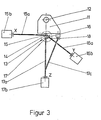
- Fig. 3 is a schematic diagram of a test setup with a force introduction element 11, which serves for example as a wheel replacement of an axle or vehicle test stand and which is connected in a suitable manner to the axle 12 to be tested.
- the force introduction element 11 has a joint arrangement or a joint node 13, which is arranged at the theoretical force introduction point or wheel contact point (RAP) 14.
- the joint node 13 consists of three play-free ball joints 15, 16, 17, which are connected to force transmission elements, for example tension / compression rods 15a, 16a, 17a.
- force or paths can be introduced into the joint node 13 via the force transmission elements and via actuating elements 15b, 16b, 17b.
- the actuating elements 15b, 16b, 17b can be designed, for example, as hydraulic actuating cylinders.
- the theoretical force introduction point or wheel contact point 14 coincides with the center of the ball joint 15, i.e. the ball joint 15 is arranged at the theoretical force introduction point 14.
- the two remaining joints 16 and 17 are in close proximity to joint 15 and RAP 14, respectively.
- the directions of action of the rods 15a, 16a, 17a are essentially perpendicular to one another and intersect at the wheel contact point 14 or at the theoretical point of force application.
- the effectiveness of the rod 15a defines the x direction, that of the rod 16a the y direction and that of the rod 17a the z direction.
- the bars 15a, 16a therefore form the xy plane, the bars 15a, 17a the xz plane and the bars 16a, 17a the yz plane.
- a further joint 18 is arranged on the force introduction element 11.
- This joint is connected to the rod 17a via an auxiliary rod 17c and serves to support the torque of the force introduction element 11 rotatably mounted on the axis 12, e.g. when longitudinal forces are introduced via the joint 15 and the rod 15a. If the force introduction element 11 is firmly connected to the axis 12, e.g. in tests with the wheel braked, the auxiliary rod 17c is omitted or it is switched off or removed.
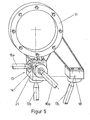
- FIG. 5 shows the joint arrangement 13 with the force introduction element 11 and the application of the auxiliary rod 17c in a perspective sketch.
- the reference numerals correspond to those in FIG. 3.
- the sketch also shows the base body 21 of the joint arrangement shown in FIGS. 4a-c in a more concrete, but still schematically illustrated form.
- the force introduction element 11 is in FIG. 5 as one in essence Lichen round element shown. However, as indicated in FIG. 3, it can also have a trapezoidal shape or another suitable shape.
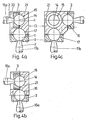
- the sections shown in FIGS. 4a-c through the joint arrangement or the joint node 13 with a base body 21 each pass through the theoretical force introduction point or wheel contact point 14.
- the base body 21 can be designed, for example, as a cubic or rectangular body and cylindrical approaches for individual ball joints exhibit.
- Fig. 4a with the section in the xz plane shows the play-free ball joint 15 with the ball head 1 and the ball pin 2.
- the ball pin 2 is connected to the rod 15a in a suitable manner, e.g. welded.
- the ball joint 15 is arranged in a recess 22 of the base body 21.
- a bearing shell 3 is provided with an opening, via which the ball head 1 is connected to the base body 21 in the manner described above.
- the clamping and loosening screws required for this are arranged on the bearing shell 3 and are only indicated schematically for the sake of clarity.
- the ball joint 17 is arranged in the base body 22 below the ball joint 15.
- the ball joint 17 is made larger than the ball joint 15, so that higher forces can be transmitted via the joint 17.
- a ball head 1 is connected to a ball pin 2 in ball joint 17 and this is connected to rod 17a. Via a bearing shell 3 provided with an opening, the ball head 1 is supported in the base body 21 without play by means of clamping and loosening screws.
- FIGS. 4b and 4c show the sections corresponding to FIG. 4a in the xy plane passing through the force introduction point 14 and the yz plane with the wheel contact point 14, the ball joints 15, 16, 17, the tension / compression rods 15a, 16a, 17a , the bearing shells 3 and the base body 21. All three ball joints can be seen in FIG. 4c, since they lie in the yz sectional plane shown here.
- the ball joints can also be arranged so that all joints are in the xy or xz plane.
- the joint node 13 can also have only two joints instead of three ball joints.
- the individual ball joints can be shown in a manner not shown by cuffs or similar sealing elements e.g. be sealed against dust.
- the sleeves or sealing elements can e.g. be arranged between the tension / compression rods 15a, 16a, 17a and the base body 21.
Abstract
Description
Spielfreies Kugelgelenk, insbesondere für Prüfeinrichtungen, und Gelenkanordnung mit solchen KugelgelenkenBacklash-free ball joint, in particular for test facilities, and joint arrangement with such ball joints
Die Erfindung betrifft ein spielfreies Kugelgelenk, insbesondere für Prüfeinrichtungen, mit einem Kugelkopf, der einen Kugelzapfen aufweist, an dem im wesentlichen in der Zapfenachse wirkende Zug- und Druckkräfte angreifen, mit zwei Lagerschalen zur gelenkigen Lagerung des Kugelkopfes, von denen eine Lagerschale ein Durchbruch für den Kugelzapfen aufweist, wobei die Trennebene zwischen den beiden Lagerschalen im wesentlichen senkrecht zur Zapfenachse bzw. zur Belastungsrichtung liegt und zwischen den Lagerschalen ein Abstand bzw. Spalt verbleibt, sowie eine Gelenkanordnung mit solchen Kugelgelenken.The invention relates to a play-free ball joint, in particular for test equipment, with a ball head which has a ball pin on which tensile and compressive forces act essentially in the pin axis, with two bearing shells for the articulated mounting of the ball head, one of which bearing hole is a breakthrough for has the ball stud, the parting plane between the two bearing shells being essentially perpendicular to the pin axis or to the direction of loading and a distance or gap remaining between the bearing shells, and a joint arrangement with such ball joints.
Bei einem bekannten spielfreien Kugelgelenk, das in erster Linie bei Lenkgetängen von Fahrzeugen verwendet wird (DE-AS 1 916 579), sind die Lagerkörper bzw. Lagerschalen elastisch ausgebildet. Ein solches Gelenk ist für hohe Kräfte nicht geeignet und weist keine Nachstellmöglichkeit auf. Bei Kugelgelenken die beispielsweise bei Prüfeinrich- tungen verwendet werden, darf bei Kraftumkehr (Zug- Druck) kein Spiel vorhanden sein. Trotzdem soll das Gelenk leicht beweglich sein und hohe Prüfkräfte übertragen.In a known backlash-free ball joint, which is primarily used in steering rods of vehicles (DE-AS 1 916 579), the bearing bodies or bearing shells are designed to be elastic. Such a joint is not suitable for high forces and has no possibility of adjustment. In the case of ball joints, which are used, for example, in test facilities , there must be no play when the force is reversed (tension-compression). Nevertheless, the joint should be easy to move and transmit high test loads.
Bei der Prüfung von Fahrzeugen unter Bedingungen, die dem Fahrversuch auf der Straße entsprechen, werden auf Prüfständen Kräfte in den drei Achsrichtungen x, y, z eines räumlichen Koordinatensystems in die Fahrzeugräder oder in die die Räder ersetzenden Krafteinletungselemente eingeleitet. Bei Achs- und Karosserieprüfständen ist es daher wünschenswert, die von der Prüfeinrichtung-in das Prüfobjekt einzuleitenden Kräfte an einem theoretischen Krafteinleitungspunkt aufzubringen, an dem die Kräfte in Wirklichkeit, z.B. beim Betrieb eines Fahrzeugs auf der Straße, auftreten. Ein solcher theoretischer Krafteinleitungspunkt ist z.B. der Radaufstandspunkt (RAP). Die gemeinsame Einleitung von mehreren Kräften an einem Punkt bereitet jedoch Schwierigkeiten.When testing vehicles under conditions that correspond to driving tests on the road, forces in the three axial directions x, y, z of a spatial coordinate system are introduced into the vehicle wheels or into the force introduction elements replacing the wheels on test benches. In the case of axle and body test stands, it is therefore desirable to apply the forces to be introduced into the test object by the test device at a theoretical force introduction point at which the forces actually occur, for example when a vehicle is operated on the road, occur. Such a theoretical force introduction point is, for example, the wheel contact point (RAP). However, it is difficult to initiate several forces together at one point.
Die bisher bekannten Lösungen bei Achs- und Karosserieprüfständen weisen eine Reihe von Nachteilen auf, wie z.B. komplizierter Aufbau, zu großer Abstand der tatsächlichen Krafteinleitungspunkte vom theoretisch richtigen Krafteinleitungspunkt, großes Gewicht bzw. große Masse, Spiel an den Gelenken (ergibt Probleme bei geregelten Einrichtungen sowie Verschleißprobleme), schlechte Zugänglichkeit u.a..The previously known solutions for axle and body test benches have a number of disadvantages, such as complicated structure, too great a distance between the actual force application points and the theoretically correct force application point, great weight or mass, play on the joints (results in problems with controlled devices and wear problems), poor accessibility etc.
Es ist Aufgabe der vorliegenden Erfindung, ein insbesondere für Prüfeinrichtungen verwendbares spielfreies Kugelgelenk zu schaffen, das die Übertragung hoher, insbesondere dynamischer Kräte ermöglicht, leicht nachstellbar ist und geringe Reibung im Gelenk aufweist, d.h. leicht beweglich ist. Diese Aufgabe wird durch die in Patentanspruch 1 angegebenen Merkmale gelöst.It is an object of the present invention to provide a backlash-free ball joint which can be used in particular for test facilities and which enables the transmission of high, in particular dynamic, loads, is easily adjustable and has low friction in the joint, i.e. is easy to move. This object is achieved by the features specified in
Eine weitere Aufgabe der Erfindung beteht darin, die bei Achs- und Karosserieprüfständen entstehenden Schwierigkeiten bei der gemeinsamen Einleitung von mehreren Kräften an einem Punkt zu beseitigen.Another object of the invention is to eliminate the difficulties encountered in axle and body test benches in the joint introduction of several forces at one point.
Durch die Verwendung von Klemm- und Entlastungselementen zur Verspannung der beiden Lagerschalen gegeneinander bzw. gegen den Kugelkopf kann das Spiel des Gelenks leicht eingestellt und, falls erforderlich, nachgestellt werden.Through the use of clamping and relief elements for bracing the two bearing shells against each other or against the ball head, the play of the joint can be easily adjusted and, if necessary, readjusted.
Insbesondere wird jedoch durch die Vorspannung der Klemmelemente erreicht, daß die dynamische Belastung dieser Elemente sehr niedrig bleibt. Ohne Entlastungs- oder Löseelemente müßten die Klemmelemente für die Übertragung der gleichen Kräfte um ein Vielfaches stärker dimensioniert werden. Darüberhinaus wären zusätzliche Sicherungen an den Klemmelementen gegen das Lösen dieser Elemente erforderlich.In particular, however, the pretensioning of the clamping elements ensures that the dynamic loading of these elements remains very low. Without relief or release elements, the clamping elements would have to be dimensioned many times stronger for the transmission of the same forces. In addition, additional safeguards on the clamping elements against loosening of these elements would be required such.
Eine zweckmäßige Ausgestaltung ergibt sich, wenn die Klemm-und Entlastungselemente als Schrauben ausgebildet werden, so daß die Einstellung und Nachstellung des Lagers auf einfache Weise vorgenommen werden kann. Anstelle der Löseschrauben können auch geeignet ausgebildete Federelemente oder Zwischenelemente verwendet werden, deren Federrate vorteilhafterweise größer ist als die Federrate der Klemmschrauben. Zur Verbesserung des Verschleiß- und/oder Reibverhaltens kann der Kugelkopf und/oder die Lagerschalen mit einer Beschichtung versehen werden, die günstige Reib-und Verschleißwerte aufweist.An expedient embodiment results if the clamping and relief elements are designed as screws, so that the adjustment and readjustment of the bearing can be carried out in a simple manner. Instead of the loosening screws, suitably designed spring elements or intermediate elements can also be used, the spring rate of which is advantageously greater than the spring rate of the clamping screws. In order to improve the wear and / or friction behavior, the ball head and / or the bearing shells can be provided with a coating which has favorable friction and wear values.
Die Vorteile der erfindungsgemäßen Gelenkanordnung sind insbesndere darin zu sehen, daß die einzelnen Gelenkpunkte einen sehr kleinen Abstand zueinander aufweisen, leicht nachstellbar sind und daß die Gelenkanordnung eine kleine Masse hat. Die Spielfreiheit der Gelenkanordnung vermeidet Schwierigkeiten, wie sie beispielsweise bei geregelten Anlagen bei der Aufbringung von Kräften mit wechselnder Richtung (Zug/Druck) auftreten können.The advantages of the joint arrangement according to the invention can be seen in particular in the fact that the individual joint points are at a very small distance from one another, are easily adjustable and that the joint arrangement has a small mass. The freedom from play of the joint arrangement avoids difficulties, such as can occur, for example, in the case of regulated systems when applying forces with changing directions (tension / compression).
Die weiteren Unteransprüche betreffen andere vorteilhafte Ausgestaltungen der Erfindung.The further subclaims relate to other advantageous refinements of the invention.
Die Erfindung wird nachstehend an Ausführungsbeispielen in den Zeichnnen dargestellt und in der Beschreibung näher erläutert. Es zeigen:
- Fig. 1 Schnitt durch ein spielfreies Kugelgelenk nach der Erfindung mit Klemm- und Löseschrauben,
- Fig. 2 Schnitt durch ein spielfreies Kugelgelenk mit Gewindering und Klemmschrauben (Fig. 2a) bzw. mit Gewindering und Löseschrauben (Fig. 2b)
- Fig. 3 Prüfaufbau mit einer Gelenkanordnung mit drei spielfreien Kugelgelenken für die Einleitung von drei Kräften in ein Prüfobjekt, beispielsweise in eine Fahrzeugachse
- Fig. 4 Schnitte durch den Grundkörper einer Gelenkanordnung mit drei spielfreien Kugelgelenken in drei Ebenen, die jeweils durch den theoretischen Krafteinleitungspunkt gehen, und zwar
- Fig.. 4a Schnitt in der xz-Ebene,
- Fig. 4b Schnitt in der xy-Ebene,
- Fig. 4c Schnitt in der yz-Ebene
- Fig. 5 Gelenkanordnung mit drei spielfreien Kugelgelenken in einem Grundkörper und einem Krafteinleitungselement (perspektivisch).
- 1 section through a play-free ball joint according to the invention with clamping and loosening screws,
- 2 section through a play-free ball joint with a threaded ring and clamping screws (Fig. 2a) or with a threaded ring and loosening screws (Fig. 2b)
- Fig. 3 test setup with a joint arrangement with three play-free ball joints for the introduction of three forces into a test object, for example in a vehicle axle
- Fig. 4 sections through the base body of a joint arrangement with three play-free ball joints in three planes, each going through the theoretical point of force application, namely
- 4a section in the xz plane,
- 4b section in the xy plane,
- Fig. 4c section in the yz plane
- Fig. 5 joint arrangement with three play-free ball joints in a base body and a force introduction element (in perspective).
Das Kugelgelenk nach Fig. 1 weist einen Kugelkopf 1 mit einem Kugelzapfen 2 auf, an den ein Kraftübertragungselement (nicht dargestellt) zur Einleitung von Zug- und Druckkräften (± F) angeschlossen werden kann. Der Kugelkopf 1 ist in zwei Lagerschalen 3 und 4 aufgnommen. Die Lagerschale 3 weist einen Durchbruch zur Durchführung des Kugelzapfens 2 auf. Die Lagerschale 4 kann in nicht dargestellter Weise z.B. mit dem zu prüfenden Bauteil verbu-den sein. Die Trennebene zwischen den beiden Lagerschalen 3 und 4 liegt etwa senkrecht zur Belastungsrichtung (Kraft ± F) bzw. zur Achse des Kugelzapfens 2.1 has a
Die beiden Lagerschalen 3 und 4 sind dunh Klemmschrauben 5, die an der Lagerschale 3 angeordnet sind, gegeneinander bzw. gegen den Kugelkopf 1 verspannt. Die Größe und Anzahl der Schrauben sowie die Vorspannkraft der Klemmschrauben 5 wird so gewählt, daß die am Kugelgelenk auftretenden statischen und dynamischen Belastungskräfte einwandfrei übertragen werden können.The two bearing
Die Klemmkraft der Klemmschrauben 5 auf den Kugelkopf 1 wird durch Löseschrauben 6,..die in der Lagerschale 4 eingesetzt sind und gegen die Lagerschale 3 drücken, teilweise wieder aufgehoben und zwar so weit, bis das gewünschte Spiel bzw. die gewünschte Leichtgängigkeit zwischen Kugelkopf und Lagerschalen hergestellt ist. Die Klemmschrauben 5 werden hierbei hoch vorspannt. Die hohe Vorspannung bewirkt, daß bei allen dynamischen Belastungen z.B. bei Schwellbelastungen oder bei Wechsellasten, die Klemmschrauben 5 nur einer kleinen zusätzlichen Belastung ausgesetzt sind, da der dynamische Betriebslastanteil der Klemmschrauben klein bleibt. Das gleiche trifft zu, wenn die Klemmschrauben durch harte Federelement, Zwischenele- .mente oder in anderer geeigneter Weise vorgespannt werden.The clamping force of the
Mit Hilfe der Löseschrauben 6 ist es weiterhin möglich, das Spiel zwischen Kugelkopf 1 und Lagerschalen 3, 4 bei Verschleiß nachzustellen. Hierzu werden die Löseschrauben 6 so weit gelöst, bis das gewünschte Spiel am Kugelgelenk wieder hergestellt ist.With the help of the
Um die Reibung des Laders möglichst niedrig zu halten, können der Kugelkopf und/oder die Lagerschalen mit einer Gleitschicht 7 aus einem geeigneten Werkstoff, z.B. PTFE, Polyimid, Lagerbronze usw. beschichtet werden.In order to keep the loader's friction as low as possible, the ball head and / or the bearing shells can be provided with a sliding
Die Größe und Anzahl der Löseschrauben 6 sowie die Abstützlänge dieser Schrauben wird so gewählt, daß die Löseschrauben eine möglichst harte Feder darstellen. Unter Abstützlänge der Löseschrauben 6 ist hierbei im wesentlichen die freie Länge der Schrauben zwischen den beiden Lagerschalen 3 und 4 zu verstehen.The size and number of the loosening
Die Klemmschrauben 3 und die Löseschrauben 4 können entgegen der Darstellung in Fig. 1 auch an einer Lagerschale, d.h. entweder an der Lagerschale 3 oder an der Lagerschale 4 angeordnet werden.Contrary to the illustration in Fig. 1, the clamping screws 3 and the loosening screws 4 can also be attached to a bearing shell, i.e. can be arranged either on the bearing
Fig. 2 zeigt Anordnungen, bei denen die Klemm- oder Löseschrauben durch die Anordnung von Gewinden an einer Lagerschale und zweckentsprechende Gegengewinde ersetzt sind.Fig. 2 shows arrangements in which the clamping or loosening screws are replaced by the arrangement of threads on a bearing shell and appropriate counter threads.
In Fig. 2a weist die Lagerschale 3 an ihrem äußeren Umfang ein Gewinde 8 auf, mit dem sie in einem Gewindering 9 geführt ist. Die Lagerschale wird durch die Klemmschrauben 5 gegen den Kugelkopf 1 bzw. die Lagerschale 4 verspannt. Mit Hilfe des Gewinderinges 9 kann in ähnlicher Weise wie mit den Löseschrauben das Lager eingestellt bzw. die Varspannung der Klemmschrauben aufgebracht werden.In Fig. 2a, the bearing
Im Ausführungsbeispiel nach Fig. 2b ist die Lagerschale 3 mit Hilfe eines Gewindes 8 in die Lagerschale 4 eingesetzt und gegen den Kugelkopf 1 bzw. die Lagerschale 4 verspannt. Mit den Löseschrauben 6 wird das Gelenk wie bei Fig. 1 beschrieben eingestellt.In the exemplary embodiment according to FIG. 2 b, the bearing
In Fig. 3 ist in einer Schemaskizze ein Prüfaufbau dargestellt mit einem Krafteinleitungselement 11, das beispielsweise als Radersatz eines Achs- oder Fahrzeugprüfstandes dient und das in geeigneter Weise mit der zu prüfenden Achse 12 verbunden ist. Das Krafteinleitungselement 11 weist eine Gelenkanordnung oder einen Gelenkknoten 13 auf, der am theoretischen Krafteinleitungspunkt oder Radaufstandspunkt (RAP) 14 angeordnet ist. Der Gelenkknoten 13 besteht aus drei spielfreien Kugelgelenken 15, 16, 17, die mit Kraftübertragurgselementen, z.B. Zug-/Druckstäben 15a, 16a, 17a verbunden sind. über die Kraftübertragungselemente und über Betätigungselemente 15b, 16b, 17b können z.B. Kräfte oder Wege in den Gelenkknoten 13 eingeleitet werden. Die Betätigungselemente 15b, 16b, 17b können z.B. als hydraulische Betätigungszylinder ausgebildet sein.In Fig. 3 is a schematic diagram of a test setup with a
Bei der dargestellten Anordnung fällt der theoretische Krafteinleitungspunkt bzw. Radaufstandspunkt 14 mit dem Mittelpunkt des Kugelgelenks 15 zusammen, d.h. das Kugelgelenk 15 ist am theoretischen Krafteinleitungspunkt 14 angeordnet. Die beiden übrigen Gelenke 16 und 17 liegen in unmittelbarer Nähe des Gelenks 15 bzw.des RAP 14.In the arrangement shown, the theoretical force introduction point or
Die Wirkungsrichtungen der Stäbe 15a, 16a, 17a stehen im wesentlichen senkrecht aufeinander undschneiden sich im Radaufstandspunkt 14 bzw. im theoretischen Krafteinleitungspunkt. Die WirkungsricHung des Stabes 15a definiert die x-Richtung, die des Stabes 16a die y-Richtung und die des Stabes 17a die z-Richtung. Die Stäbe 15a, 16a bilden daher die xy-Ebene, die Stäbe 15a,17a die xz-Ebene und die Stäbe 16a, 17a die yz-Ebene.The directions of action of the
Am Krafteinleitungselement 11 ist ein weiteres Gelenk 18 angeordnet. Dieses Gelenk ist über einen Hilfsstab 17c mit dem Stab 17a verbunden und dient zur Drehmomentabstützung des an der Achse 12 drehbar gelagerten Krafteinleitungselements 11, z.B. bei der Einleitung von Längskräften über das Gelenk 15 und den Stab 15a. Wenn das Krafteinleitungselement 11 fest mit der Achse 12 verbunden ist, z.B. bei Prüfungen mit gebremstem Rad, entfällt der Hilfsstab 17c bzw. er wird abgeschaltet oder entfernt.A further joint 18 is arranged on the
In Fig. 5 ist die Gelenkanordnung 13 mit dem Krafteinleitungselement 11 und die Anlegung des Hilfsstabes 17c in einer perspektivischen Skizze dargestellt. Die Bezugsziffern entsprechen denen der Fig. 3. Die Skizze zeigt auch den in Fig. 4a -c mit weiteren Einzelheiten dargestellten Grundkörper 21 der Gelenkanordnung in einer konkreteren, jedoch immer noch schematisch dargestellten Form. Das Krafteinleitungselement 11 ist in Fig. 5 als ein im wesentlichen rundes Element dargestellt. Es kann jedoch auch, wie in Fig. 3 angedeutet, Trapezform oder eine andre geeignete Form aufweisen.5 shows the
Die in den Figuren 4a - c dargestellten Schnitte durch die Gelenkanordnung bzw. den Gelenkknoten 13 mit einem Grundkörper 21 gehen jeweils durch den theoretischen Krafteinleitungspunkt bzw. Radaufstandspunkt 14. Der Grundkörper 21 kann beispielsweise als kubischer oder rechteckiger Körper ausgebildet sein und zylindrische Ansätze für einzelne Kugelgelenke aufweisen.The sections shown in FIGS. 4a-c through the joint arrangement or the
Die Fig. 4a mit dem Schnitt in der xz-Ebene zeigt das spielfreie Kugelgelenk 15 mit dem Kugelkopf 1 und dem Kugelzapfen 2. Der Kugelzapfen 2 ist mit dem Stab 15a in geegneter Weise verbunden, z.B. verschweißt.Fig. 4a with the section in the xz plane shows the play-free ball joint 15 with the
Das Kugelgelenk 15 ist in einer Ausdrehung 22 des Grundkörpers 21 angeordnet. In die Ausdrehung 22 ist eine mit einem Durchbruch versehene Lagerschale 3 eingesetzt, über die der Kugelkopf 1 mit dem Grundkörper 21 in der oben beschriebenen Weise verbunden ist. Die hierfür erforderlichen Klemm- und Löseschrauben sind an der Lagerschale 3 angeordnet und der Übersichtlichkeit halber nur schematisch angedeutet.The ball joint 15 is arranged in a
Unterhalb des Kugelgelenks 15 ist das Kugelgelenk 17 im Grundkörper 22 angeordnet. Das Kugelgelenk 17 ist größer ausgebildet als das Kugelgelenk 15, so daß über das Gelenk 17 höhere Kräfte übertragbar sind.The ball joint 17 is arranged in the
In gleicher Weise wie bei Kugelgelenk 15 ist bei Kugelgelenk 17 ein Kugelkopf 1 mit einem Kugelzapfen 2 und dieser mit dem Stab.17a verbunden. Über eine mit einem Durchbruch versehene Lagerschale 3 ist der Kugelkopf 1 mit Hilfe von Klemm- und Löseschrauben spielfrei im Grundkörper 21 gelagert.In the same way as with ball joint 15, a
Die Figuren 4b und 4c zeigen die der Figur 4a entsprechenden Schnitte in der durch den Krafteinleitungspunkt 14 gehenden xy-Ebene und der yz-Ebene mit dem Radaufstandspunkt 14, den Kugelgelenken 15, 16, 17, den Zug-/ Druckstäben 15a, 16a, 17a,den Lagerschalen 3 sowie dem Grundkörper 21. In der Figur 4c sind alle drei Kugelgelenke erkennbar, da sie in der hier dargestellten yz-Schnittebene liegen.FIGS. 4b and 4c show the sections corresponding to FIG. 4a in the xy plane passing through the
Die Kugelgelenke können auch so angeordnet werden, daß alle Gelenke in der xy- oder xz-Ebene liegen.The ball joints can also be arranged so that all joints are in the xy or xz plane.
Der Gelenkknoten 13 kann anstelle von drei Kugelgelenken auch lediglich zwei Gelenke aufweisen.The
Bei einem Gelenkknoten mit drei Gelenken können diese auch mit gleichem Abstand zu einem theoretischen Krafteinleitungspunkt angeordnet werden.In the case of a joint node with three joints, these can also be arranged at the same distance from a theoretical force introduction point.
Die einzelnen Kugelgelenke können in nicht dargestellter Weise durch Manschetten oder ähnliche Dichtelemente z.B. gegen Staub abgedichtet werden. Die Manschetten oder Dichtelemente können z.B. zwischen den Zug-/Druckstäben 15a, 16a, 17a und dem Grundkörper 21 angeordnet sein.The individual ball joints can be shown in a manner not shown by cuffs or similar sealing elements e.g. be sealed against dust. The sleeves or sealing elements can e.g. be arranged between the tension /
Claims (14)
Applications Claiming Priority (4)
| Application Number | Priority Date | Filing Date | Title |
|---|---|---|---|
| DE3301543 | 1983-01-19 | ||
| DE19833301543 DE3301543A1 (en) | 1983-01-19 | 1983-01-19 | Play-free ball joint, especially for test devices |
| DE19833310064 DE3310064A1 (en) | 1983-03-19 | 1983-03-19 | Joint arrangement with play-free ball-and-socket joints, in particular for test devices |
| DE3310064 | 1983-03-19 |
Publications (3)
| Publication Number | Publication Date |
|---|---|
| EP0114327A2 true EP0114327A2 (en) | 1984-08-01 |
| EP0114327A3 EP0114327A3 (en) | 1985-01-16 |
| EP0114327B1 EP0114327B1 (en) | 1987-03-18 |
Family
ID=25807619
Family Applications (1)
| Application Number | Title | Priority Date | Filing Date |
|---|---|---|---|
| EP83112734A Expired EP0114327B1 (en) | 1983-01-19 | 1983-12-17 | Play-free ball-joint, in particular for test-equipment and joint assembly comprising such ball-joints |
Country Status (2)
| Country | Link |
|---|---|
| EP (1) | EP0114327B1 (en) |
| DE (1) | DE3370363D1 (en) |
Cited By (9)
| Publication number | Priority date | Publication date | Assignee | Title |
|---|---|---|---|---|
| EP0181411A1 (en) * | 1984-11-03 | 1986-05-21 | Carl Schenck Ag | Arrangement for applying forces to a common (force-applying) point |
| EP0183065A2 (en) * | 1984-11-29 | 1986-06-04 | Fritz Sträter | Desk lamp |
| EP0213504A2 (en) * | 1985-08-15 | 1987-03-11 | Rockwell International Corporation | Two jaw chuck and recessed jaw element |
| GB2296288A (en) * | 1994-12-16 | 1996-06-26 | Kenex | Mount for a radiation shield |
| US5720594A (en) * | 1995-12-13 | 1998-02-24 | Holmes Products Corp. | Fan oscillating in two axes |
| WO1998050707A1 (en) | 1997-05-01 | 1998-11-12 | Mikron S.A. Agno | Hydrostatic joint |
| EP1209456A1 (en) * | 2000-11-23 | 2002-05-29 | Benteler Automobiltechnik GmbH & Co. KG | Arrangement for the simulation of the influence of forces on a vehicle wheel |
| WO2005106264A1 (en) * | 2004-05-03 | 2005-11-10 | Wabtec Holding Corporation | System for self-lubricating a coupling system |
| FR3056654A1 (en) * | 2016-09-29 | 2018-03-30 | Centre Technique Des Industries Mecaniques | DEVICE FOR ANCHORING THE END OF A SWIVEL ROD |
Citations (4)
| Publication number | Priority date | Publication date | Assignee | Title |
|---|---|---|---|---|
| FR1369413A (en) * | 1963-06-10 | 1964-08-14 | Citroen Sa Andre | Ball joint arrangement for steered wheels of a hydropneumatic suspension vehicle |
| US3744859A (en) * | 1969-05-15 | 1973-07-10 | Caterpillar Tractor Co | Multi-part bearing liner |
| GB2074337A (en) * | 1980-04-15 | 1981-10-28 | Univ Technology | Adjustable support for an optical or other instrument |
| FR2505952A1 (en) * | 1981-05-15 | 1982-11-19 | Citroen Sa | Multiple rotary steering joint - has hemi-spherical housings for shafts which hinge about common axis |
-
1983
- 1983-12-17 EP EP83112734A patent/EP0114327B1/en not_active Expired
- 1983-12-17 DE DE8383112734T patent/DE3370363D1/en not_active Expired
Patent Citations (4)
| Publication number | Priority date | Publication date | Assignee | Title |
|---|---|---|---|---|
| FR1369413A (en) * | 1963-06-10 | 1964-08-14 | Citroen Sa Andre | Ball joint arrangement for steered wheels of a hydropneumatic suspension vehicle |
| US3744859A (en) * | 1969-05-15 | 1973-07-10 | Caterpillar Tractor Co | Multi-part bearing liner |
| GB2074337A (en) * | 1980-04-15 | 1981-10-28 | Univ Technology | Adjustable support for an optical or other instrument |
| FR2505952A1 (en) * | 1981-05-15 | 1982-11-19 | Citroen Sa | Multiple rotary steering joint - has hemi-spherical housings for shafts which hinge about common axis |
Cited By (11)
| Publication number | Priority date | Publication date | Assignee | Title |
|---|---|---|---|---|
| EP0181411A1 (en) * | 1984-11-03 | 1986-05-21 | Carl Schenck Ag | Arrangement for applying forces to a common (force-applying) point |
| EP0183065A2 (en) * | 1984-11-29 | 1986-06-04 | Fritz Sträter | Desk lamp |
| EP0183065A3 (en) * | 1984-11-29 | 1988-05-04 | Fritz Strater | Desk lamp |
| EP0213504A2 (en) * | 1985-08-15 | 1987-03-11 | Rockwell International Corporation | Two jaw chuck and recessed jaw element |
| EP0213504A3 (en) * | 1985-08-15 | 1988-03-23 | Rockwell International Corporation | Two jaw chuck and recessed jaw element |
| GB2296288A (en) * | 1994-12-16 | 1996-06-26 | Kenex | Mount for a radiation shield |
| US5720594A (en) * | 1995-12-13 | 1998-02-24 | Holmes Products Corp. | Fan oscillating in two axes |
| WO1998050707A1 (en) | 1997-05-01 | 1998-11-12 | Mikron S.A. Agno | Hydrostatic joint |
| EP1209456A1 (en) * | 2000-11-23 | 2002-05-29 | Benteler Automobiltechnik GmbH & Co. KG | Arrangement for the simulation of the influence of forces on a vehicle wheel |
| WO2005106264A1 (en) * | 2004-05-03 | 2005-11-10 | Wabtec Holding Corporation | System for self-lubricating a coupling system |
| FR3056654A1 (en) * | 2016-09-29 | 2018-03-30 | Centre Technique Des Industries Mecaniques | DEVICE FOR ANCHORING THE END OF A SWIVEL ROD |
Also Published As
| Publication number | Publication date |
|---|---|
| DE3370363D1 (en) | 1987-04-23 |
| EP0114327B1 (en) | 1987-03-18 |
| EP0114327A3 (en) | 1985-01-16 |
Similar Documents
| Publication | Publication Date | Title |
|---|---|---|
| EP0412348A2 (en) | Specimen clamping device exerting no bending moment, in particular for ceramic test piece | |
| DE3301543A1 (en) | Play-free ball joint, especially for test devices | |
| WO1999050121A1 (en) | Device for providing elastic support to the coupling shaft of the central buffer coupling in a railway vehicle | |
| DE102019101278B4 (en) | Ball joint and holding arm with such ball joints | |
| EP0114327B1 (en) | Play-free ball-joint, in particular for test-equipment and joint assembly comprising such ball-joints | |
| DE1400214B1 (en) | Vehicle suspension, especially for rail vehicles | |
| DE3000170C2 (en) | A mandrel for a pipe to be bent | |
| DE202018102171U1 (en) | Sensor holder and device with such a sensor holder | |
| DE2934207A1 (en) | HOMOKINETIC UNIVERSAL JOINT | |
| DE3446012A1 (en) | Device for machining a connecting-rod blank | |
| DE2349680A1 (en) | DEVICE FOR SUPPORTING A FIRST BODY ON A SECOND BODY IN SUCH A WAY THAT A RELATIVE MOVEMENT BETWEEN THE TWO BODIES IS ONLY POSSIBLE IN THREE VERTICAL DIRECTIONS | |
| DE3241373C2 (en) | ||
| EP0198933A2 (en) | Load restraining pivot, especially for operation microscopes and suspension therefor | |
| DE10033093B4 (en) | Device for releasably connecting rotational-system-metric components | |
| DE10165134B3 (en) | Coupling device for load carrier | |
| DE3310064A1 (en) | Joint arrangement with play-free ball-and-socket joints, in particular for test devices | |
| DE3119491A1 (en) | OVERLOAD PROTECTION CLUTCH | |
| DE4415788A1 (en) | Swing wing switch | |
| DE1750843B1 (en) | SUSPENSION DEVICE WHOSE LOADING CAPACITY REMAINS ABOUT THE SAME IN THE EVENT OF LIMITED VERTICAL MOVEMENTS OF A LOAD | |
| DE2738527A1 (en) | Clamp for cylindrical EDM tool shank - has clamping sleeves and rings, one of which is split | |
| EP0181411B1 (en) | Arrangement for applying forces to a common (force-applying) point | |
| EP0479061A1 (en) | Torsion spring | |
| DE4231323A1 (en) | Link connection between two articulated vehicles | |
| DD290849A5 (en) | ARRANGEMENT OF AXLE BEARING IN A DRIVE FOR RAIL VEHICLES | |
| DE19541709A1 (en) | Device for attaching a gear shift lever |
Legal Events
| Date | Code | Title | Description |
|---|---|---|---|
| PUAI | Public reference made under article 153(3) epc to a published international application that has entered the european phase |
Free format text: ORIGINAL CODE: 0009012 |
|
| AK | Designated contracting states |
Designated state(s): CH DE FR GB LI |
|
| PUAL | Search report despatched |
Free format text: ORIGINAL CODE: 0009013 |
|
| AK | Designated contracting states |
Designated state(s): CH DE FR GB LI |
|
| 17P | Request for examination filed |
Effective date: 19850615 |
|
| 17Q | First examination report despatched |
Effective date: 19860312 |
|
| GRAA | (expected) grant |
Free format text: ORIGINAL CODE: 0009210 |
|
| AK | Designated contracting states |
Kind code of ref document: B1 Designated state(s): CH DE FR GB LI |
|
| REF | Corresponds to: |
Ref document number: 3370363 Country of ref document: DE Date of ref document: 19870423 |
|
| ET | Fr: translation filed | ||
| PLBE | No opposition filed within time limit |
Free format text: ORIGINAL CODE: 0009261 |
|
| STAA | Information on the status of an ep patent application or granted ep patent |
Free format text: STATUS: NO OPPOSITION FILED WITHIN TIME LIMIT |
|
| 26N | No opposition filed | ||
| PGFP | Annual fee paid to national office [announced via postgrant information from national office to epo] |
Ref country code: FR Payment date: 19911107 Year of fee payment: 9 |
|
| PGFP | Annual fee paid to national office [announced via postgrant information from national office to epo] |
Ref country code: CH Payment date: 19911121 Year of fee payment: 9 |
|
| PG25 | Lapsed in a contracting state [announced via postgrant information from national office to epo] |
Ref country code: LI Effective date: 19921231 Ref country code: CH Effective date: 19921231 |
|
| PG25 | Lapsed in a contracting state [announced via postgrant information from national office to epo] |
Ref country code: FR Effective date: 19930831 |
|
| REG | Reference to a national code |
Ref country code: CH Ref legal event code: PL |
|
| REG | Reference to a national code |
Ref country code: FR Ref legal event code: ST |
|
| PGFP | Annual fee paid to national office [announced via postgrant information from national office to epo] |
Ref country code: GB Payment date: 19961121 Year of fee payment: 14 |
|
| PGFP | Annual fee paid to national office [announced via postgrant information from national office to epo] |
Ref country code: DE Payment date: 19970221 Year of fee payment: 14 |
|
| PG25 | Lapsed in a contracting state [announced via postgrant information from national office to epo] |
Ref country code: GB Free format text: LAPSE BECAUSE OF NON-PAYMENT OF DUE FEES Effective date: 19971217 |
|
| GBPC | Gb: european patent ceased through non-payment of renewal fee |
Effective date: 19971217 |
|
| PG25 | Lapsed in a contracting state [announced via postgrant information from national office to epo] |
Ref country code: DE Free format text: LAPSE BECAUSE OF NON-PAYMENT OF DUE FEES Effective date: 19980901 |