EP0112605A2 - Packaging - Google Patents
Packaging Download PDFInfo
- Publication number
- EP0112605A2 EP0112605A2 EP83304610A EP83304610A EP0112605A2 EP 0112605 A2 EP0112605 A2 EP 0112605A2 EP 83304610 A EP83304610 A EP 83304610A EP 83304610 A EP83304610 A EP 83304610A EP 0112605 A2 EP0112605 A2 EP 0112605A2
- Authority
- EP
- European Patent Office
- Prior art keywords
- conveyor
- panels
- sub
- sealing
- carton
- Prior art date
- Legal status (The legal status is an assumption and is not a legal conclusion. Google has not performed a legal analysis and makes no representation as to the accuracy of the status listed.)
- Granted
Links
Images


Classifications
-
- B—PERFORMING OPERATIONS; TRANSPORTING
- B65—CONVEYING; PACKING; STORING; HANDLING THIN OR FILAMENTARY MATERIAL
- B65D—CONTAINERS FOR STORAGE OR TRANSPORT OF ARTICLES OR MATERIALS, e.g. BAGS, BARRELS, BOTTLES, BOXES, CANS, CARTONS, CRATES, DRUMS, JARS, TANKS, HOPPERS, FORWARDING CONTAINERS; ACCESSORIES, CLOSURES, OR FITTINGS THEREFOR; PACKAGING ELEMENTS; PACKAGES
- B65D5/00—Rigid or semi-rigid containers of polygonal cross-section, e.g. boxes, cartons or trays, formed by folding or erecting one or more blanks made of paper
- B65D5/02—Rigid or semi-rigid containers of polygonal cross-section, e.g. boxes, cartons or trays, formed by folding or erecting one or more blanks made of paper by folding or erecting a single blank to form a tubular body with or without subsequent folding operations, or the addition of separate elements, to close the ends of the body
- B65D5/06—Rigid or semi-rigid containers of polygonal cross-section, e.g. boxes, cartons or trays, formed by folding or erecting one or more blanks made of paper by folding or erecting a single blank to form a tubular body with or without subsequent folding operations, or the addition of separate elements, to close the ends of the body with end-closing or contents-supporting elements formed by folding inwardly a wall extending from, and continuously around, an end of the tubular body
- B65D5/067—Gable-top containers
-
- B—PERFORMING OPERATIONS; TRANSPORTING
- B65—CONVEYING; PACKING; STORING; HANDLING THIN OR FILAMENTARY MATERIAL
- B65B—MACHINES, APPARATUS OR DEVICES FOR, OR METHODS OF, PACKAGING ARTICLES OR MATERIALS; UNPACKING
- B65B3/00—Packaging plastic material, semiliquids, liquids or mixed solids and liquids, in individual containers or receptacles, e.g. bags, sacks, boxes, cartons, cans, or jars
- B65B3/02—Machines characterised by the incorporation of means for making the containers or receptacles
- B65B3/025—Making parallelepipedal containers from a single carton blank
-
- B—PERFORMING OPERATIONS; TRANSPORTING
- B65—CONVEYING; PACKING; STORING; HANDLING THIN OR FILAMENTARY MATERIAL
- B65B—MACHINES, APPARATUS OR DEVICES FOR, OR METHODS OF, PACKAGING ARTICLES OR MATERIALS; UNPACKING
- B65B43/00—Forming, feeding, opening or setting-up containers or receptacles in association with packaging
- B65B43/24—Breaking creases to facilitate setting-up cartons
-
- B—PERFORMING OPERATIONS; TRANSPORTING
- B65—CONVEYING; PACKING; STORING; HANDLING THIN OR FILAMENTARY MATERIAL
- B65B—MACHINES, APPARATUS OR DEVICES FOR, OR METHODS OF, PACKAGING ARTICLES OR MATERIALS; UNPACKING
- B65B61/00—Auxiliary devices, not otherwise provided for, for operating on sheets, blanks, webs, binding material, containers or packages
- B65B61/28—Auxiliary devices, not otherwise provided for, for operating on sheets, blanks, webs, binding material, containers or packages for discharging completed packages from machines
Definitions
- This invention relates to packaging, particularly to the packaging of liquid, for example milk or orange juice, in cartons.
- United States Patent Specification 3239995 discloses a machine for forming, filling, closing and sealing plastics-coated paperboard cartons in which flat sleeves are successively drawn from a magazine, erected into open-ended tubular form and loaded on to mandrels of a multi-station, indexing, bottom-forming, rotary turret. From the turret, the bottom-closed cartons are conveyed successively along a tubular trackway and then carried by an indexing chain conveyor to top-breaking, filling, top-heating, top-closing and top-sealing stations and then discharged from the machine. The sleeves and cartons are thus indexed through the machine.
- United States Patent Specification 3280531 discloses a somewhat similar machine in which the opened sleeves are indexed along a stationary supporting track by a lifting comb-like structure positioned laterally of the track and having its teeth defining cells receiving the respective sleeves.
- a mandrel is inserted into the sleeve, the top and bottom closure sub-panels are folded-in about horizontal edges of the mandrel and then the mandrel is removed.
- a fin of the bottom closure is heated and, at a third station, the fin is pressure-sealed.
- the projecting bottom fin enters a slot of a slidable track component which executes a short movement laterally of the stationary track to displace the fin flatly and in the meantime a press ram enters the open top of the carton and flattens the bottom closure.
- the carton then proceeds to filling, top-folding, top-heating and top-sealing stations.
- British Patent Specification 1541910 discloses an apparatus for breaking-in, or-out, or both, end sub-panels of a gable top closure of a carton and including two forked breaking elements arranged to embrace from above the respective top edges of the end sealing sub-panels.
- Insertable into the top of the carton is a disc-like former of a ram, and two opposed stationary guides are located at the outside of the top of the carton.
- the breaking elements fold the top closure end sub-panels about edges of the former and the guides; both sub-panels are folded inwards about the ram, or both are folded outwards about the respective guides, or one sub-panel is folded inwards about the ram and the other folded outwards about one of the guides.
- the breaking elements perform somewhat reciprocatory motion, they are unsuitable for high-speed operation.
- the guides extend over only a very small part of the height of the carton, they oppose distortion of the carton over only a very small proportion of its height; in particular, they do not oppose distortion of the carton at its lower end during breaking and folding at that end.
- United States Patent Specification 4,160,406 discloses a compact high speed carton opening and sealing machine and method employing a horizontal flat sleeve feeding mechanism.
- Sleeves are fed into the opening station, positioned against a stop and vacuum opened from the trailing side panel.
- the opened horizontal sleeve is maintained in a squared position and driven through the machine by flights mounted on parallel chain conveyors adjustably positioned adjacent the long sides of the sleeve.
- the trailing and leading bottom end flaps are sequentially folded into place and then the bottom side flaps are partially folded into place. With the side flaps in a partially folded position, adhesive is applied to either or both the bottom end flaps and the bottom side flaps.
- the partially folded side flaps are then maintained in position by a fixed anvil as the carton is delivered by the conveyor to a set of squaring stops.
- a transversely moving platen then moves the carton laterally to clear the end stops while bringing the end and side flaps into sealing relationship under time and pressure conditions sufficient to effect adhesion between the side and end flaps. Thereafter, the sealed carton is ejected from the machine by the movement of the succeeding carton into the sealing station.
- the vacuum opening of the sleeve is performed by two vacuum cups applied to the lower side panel of the sleeve and to the trailing side panel, respectively, the cup applied to the latter panel being turned, relative to the other cup, about an axis parallel to but spaced inwards from the natural axis of turning of the trailing side panel relative to the lower side panel.
- This has the disadvantage of risking distortion of the sleeve, or slipping of the turning vacuum cup relative to the trailing side panel.
- a method of opening a sleeve of polygonal cross-section comprising applying first and second suction members to respective first and second walls of the sleeve and causing the first and second walls to adhere to said members by suction, and moving the first suction member relative to the second suction member along a path to open said sleeve, characterized in that said path corresponds to a natural path of movement of the first wall relative to the second wall.
- apparatus for opening a sleeve of polygonal cross-section comprising first and second suction members applicable to respective first and second walls of the sleeve, suction-producing means arranged to produce suction in said members to cause the first and second walls to adhere to said members by suction, means mounting the first suction member for movement relative to the second suction member along a path to open said sleeve, and drive means arranged to drive said first suction member along said path, characterized in that said path corresponds to a natural path of movement of the first wall relative to the second wall
- a method of producing a container containing a substance including bringing bottom parts of said container together, and sealing said bottom parts together to form a bottom closure of said container, characterized in that substantially simultaneously with said sealing, said substance is filled into said container.
- apparatus for use in producing a container containing a substance including means for bringing bottom parts of said container together and sealing said bottom parts together to form a bottom closure of said container, and filling means arranged to fill said substance into said container, characterized in that said filling means is arranged to fill said substance into said container substantially simultaneously with said sealing.
- Filling of the container substantially simultaneously with the bottom sealing has the advantage of permitting reduction of the total time taken for any one container to undergo the packaging process.
- a method of conveying articles comprising advancing said articles to a transfer location in respective pockets of a first conveyor closely receiving said articles but each open at one lateral side of the path of said articles, and operating a second conveyor transversely of the first conveyor to strip the articles from the respective pockets in the sense of said one lateral side, characterized in that the first and second conveyors continuously advance and the articles slide transversely of the second conveyor while being stripped from the pockets.
- apparatus for conveying articles comprising a first conveyor arranged to advance articles to a transfer location in respective pockets of said conveyor closely receiving said articles but each open at one lateral side of the path of said articles, and a second conveyor arranged transversely of said first conveyor to strip the articles from the respective pockets in the sense of said one lateral side, characterized in that the first and second conveyors are arranged to advance continuously and the second conveyor is such that the articles being advanced thereby can slide transversely thereof.
- a method of producing a carton containing a substance including causing said carton to be closely constrained externally by wall means at respective opposite sides of the carton, and breaking end closure sub-panels of said carton at said respective opposite sides by turning said sub-panels outwardly about said wall means, characterized in that said breaking is performed by a continuous-motion breaking device.
- apparatus for use in producing a carton containing a substance comprising wall means for closely constraining said carton externally at respective opposite sides thereof, and breaking means for turning end closure sub-panels of said carton at said respective opposite sides outwardly about said wall means to break said sub-panels, characterized in that said breaking means is a continuous-motion breaking means.
- the use of continuous-motion breaking means has the advantage of facilitating high-speed breaking.
- the external wall means advantageously extends over a considerable part of the length of the carton during breaking, preferably over the whole length of the main sub-panels of the carton, i.e. the whole spacing between the top closure and the bottom closure, in order to increase the opposition to distortion of the carton.
- a carton comprising first, second, third and fourth panels arranged in a loop around said carton, lines of weakness extending around said carton and thereby dividing said panels into loops of sub-panels including a loop of first, second, third and fourth top closure sealing sub-panels forming a sealing fin of a top closure, a loop of first, second, third and fourth top closure obturating sub-panels adjacent the row of sealing sub-panels, a loop of first, second, third and fourth bottom closure sealing sub-panels forming a sealing fin of a bottom closure, and a loop of first, second, third and fourth bottom closure obturating sub-panels adjacent the loop of bottom closure sealing sub-panels, further lines of weakness dividing the first and third bottom closure obturating sub-panels into substantially triangular sub-sub-panels, characterized in that the top closure is a gable top closure, the bottom closure is a flat bottom closure, and the said triangular sub-
- This carton is particularly suitable for continuous advance in high-speed packaging.
- the packaging machine is designed for high-speed packaging of liquid, for example milk or orange juice, in gable-topped cartons. It can attain a speed of at least 300 cartons per minute. It includes a feeder 1 for feeding flat carton sleeves 2 to a rotary sleeve-opening turret 3, which feeds the sleeves into chain pockets 4 of a continuously advancing endless conveyor chain 5 as the chain 5 passes around a rotary top pre-breaker turret 6.
- Each sleeve 2 has been made from a blank (shown in Figure 11) consisting of paperboard coated on both faces with a suitable thermoplastics.
- the pockets 4 are so designed that they closely receive the sleeves 2 with the sleeves in a fully opened, rectangular condition, the three upright walls of the pockets, and a fixed vertical guide wall along which the open side of each pocket 4 moves, substantially preventing movement of the sleeve relative to the pocket in any horizontal direction.
- a rotary horizontal supporting plate 7 of the turret 6 prevents the sleeves 2 from falling out of the pockets 4.
- the chain 5 advances the sleeves 2 along a fixed horizontal supporting plate 7 1 to over a bottom pre-breaker 8, by which bottom closure sub-panels of each carton are pre-broken along score lines, the walls of the pocket 4 and the vertical guide wall acting effectively as an encircling mandrel for maintaining the general rectangular shape of the remainder of the sleeve during this bottom pre-breaking.
- the chain 5 forwards the sleeves 2 from the pre-breaker 8 to a pair of bottom closure ploughing-in and guide rails 9, which force towards each other lateral sub-panels of the bottom closure and which guide them in a partially open condition over a bottom heater 10 which blows hot air upwards into the bottom closure, so rendering tacky the internal thermoplastics coating thereof,
- the chain 5 advances the sleeves 2 along the rails 9, which at their farther ends plough-in the lateral bottom closure sub-panels to a condition in which lateral sealing sub-panels thereof are virtually in contact with each other, whereupon the chain 5 forwards each sleeve 2 to a lead-in block 11 which is vertically slotted to receive the bottom sealing sub-panels and lead them into a pair of pre-sealing nip rollers 12.
- the chain 5 advances the carton 2' so formed to a rotary filling and bottom-sealing turret 13, in which the bottom closure sealing sub-panels are held together for a relatively long time to give good sealing, and the liquid is filled into the carton which, since the liquid is cool, also assists sealing.
- a carton being bottom-sealed in indicated at 2' in Figure 1 from which it will be noted that triangular parts of the bottom closure thereof project below the walls of the pocket 4.
- the chain 5 passes around this turret and forwards the filled cartons to a top tucker 14, from which the chain carries the cartons along between a pair of top closure ploughing-in and guide rails 15, above which is a top heater 16 which blows hot air downwards onto top closure sub-panels of the carton to render tacky the thermoplastics coatings thereof.
- the chain 5 advances the cartons from the top heater 16 to a top sealer 17 consisting of a pair of horizontal endless chains 18 each provided with a series of horizontal sealing jaws 19.
- the jaws 19 of the two chains 18 come together in pairs to grip between them gable top closure sealing sub-panels of the carton to form the gable top closure sealing fin.
- the chain 5 advances the sealed cartons to a transfer location at which a continuously advancing conveyor 20 strips the sealed cartons from the continuously advancing chain 5.
- the conveyor 20 consists of two endless chains 21 and 22 arranged parallely to each other and each moving along an endless path arranged in a vertical plane, the chain 21 being arranged above the chain 5 and the chain 22 being arranged below the same.
- Each of the chains 21 and 22 includes slats 23 extending parallely to the conveyor 5, the lower run of the chain 21 and the upper run of the chain 22 moving in the same direction as each other, namely horizontally perpendicularly outwards of the return run of the chain 5.
- the slats 23 of the lower run of the chain 21 and the slats 23 of the upper run of the chain 22 come to bear against the respective top and bottom fins of the cartons 2' arriving at the transfer station and thereby push laterally outwards the cartons in the respective chain pockets 4, although the chain 5 continues to push the cartons towards the turret 6, which it can do because the slats 23 allow sliding of the cartons transversely of the conveyor 20.
- the conveyor 20, which is relatively short, moves at the same speed as a second transverse conveyor 24, which again consists of a pair of upper and lower endless chains 25 and 26 provided with slats 27.
- the feeder 1 includes horizontal guide rails 30 for the flat sleeves 2, a pack of flat sleeves 2 (not shown) being advanced stepwise by pressing fingers 31 mounted on respective slide blocks 32 themselves guided on respective guide rods 33.
- the blocks 32 are advanced stepwise in synchronism by respective drive chains 34.
- the sleeves 2 are supported by a horizontal rail 35 and are there stripped one-by-one from the end of the pack by a lug (not shown) provided on a horizontal endless conveying chain 36.
- the lug pushes the stripped sleeve into a nip between a driven roller 37 and an idler roller 38.
- the rollers 37 and 38 advance the sleeve into a position in which it is face-to-face with one of eight identical suction pads 39 (see Figures 5 and 6), against which the sleeve is pressed by a pressing-on roller device 40 shown in more detail in Figure 4.
- the device 40 includes a vertical shaft 41 to the upper end of which is fixed a radial arm 42 which at its forked outer end is provided with a double roller arrangement 43 which is embraced by the forked outer end of the arm 42 and which is guided for movement in the fork by means of a horizontal stud 44 fixed thereto.
- the roller arrangement 43 is urged outwardly by a helical compression spring 45 encircling the stud 44 and is limited as to its outward movement by nuts 4C on the stud 44.
- the shaft 41 swings the roller arrangement 43 to a position in which it presses the sleeve 2 against the suction pad 39 and at the same time causes the sleeve 2 to depress and thus open a valve closure member 47 of a valve 48 of the pad 39.
- the sleeve opening turret 6 comprises a fixed, vertical central axle 50 to the upper end of which is keyed a horizontal cam plate 51 formed with a continuous camming slot 52.
- a vacuum line 53 which terminates at its upper end in a distributor valve 54, a rotary upper part 55 of which is connected via respective suction tubes 56 to the suction pads 39.
- a co-axial tubular body 57 which is driven at a toothed ring 68 and to which the rotary part 55 is attached by a strap 58.
- the body 57 has the suction pads 39 distributed around the wider, upper part thereof.
- each bracket 59 Arranged on the body 57 adjacent to the respective pads 39 are eight cranked suction brackets 59 each provided with three small suction pads 60.
- Each pad 60 is similar toeach pad 39 in incorporating a valve openable by depression of its valve closure member by contact with a flat sleeve 2.
- Each bracket 59 is swingable about a vertical axis in vertical bearings 61 mounted in respective horizontal flanges 69 of the wider upper part of the body 57.
- each bracket 59 has fixed thereto a pinion 62 of a rack-and-pinion device 62, 63 of which the rack 63 is fixed to a slide bar 64 guided in the body 57 and mounting at its inner end a roller follower 65 which runs in the slot 52.
- Each tube 56 has a branch duct 66 therefrom leading via a connector 67 to the upper end of the bracket 59, most of which is hollow so that suction can be applied to the pads 60.
- the continuously rotating turret brings the sleeve 2 from a position shown at a in Figure 1, in which one of two adjacent panels of the flat sleeve are held by suctio:.
- the top pre-breaker turret 6 comprises a plurality of top pre-breakers 70 equi-angularly spaced around the turret 6 and arranged to coincide in vertical alignment with the chain pockets 4 as these latter move around the turret 6.
- the turret comprises a fixed vertical central axle 71 on which is mounted a rotary body 72 carrying the pre-breakers 70. Encircling the axle 71 is a fixed sleeve 73 formed with a continuous external peripheral camming slot 74.
- a roller follower 75 attached to the lower end of a reciprocatory vertical rod 76 which is guided in linear bearings 77 in the body 72, Encircling the upper part of the rod 76 is a sleeve 78 in which the rod 76 is mounted by way of linear bearings 79.
- a helical compression spring 80 acts between an annular washer 81 supported by an upwardly facing internal shoulder of the sleeve 78 and a flanged bush 82 encircling and retained on the upper end of the rod 76.
- the sleeve 78 is attached to a vertical slide 83 mounted in a vertical guide 84 forming part of the body 72.
- a radially outwardly projecting bracket 85 supporting, at respective lateral sides thereof, respective bearings 86 mounting respective cranked shafts 87 having respective pinions 88 fixed to the inner ends thereof.
- the pinions 88 mesh with respective vertical racks 89 fixed to respective opposite sides of the rod 76.
- the crank in each shaft 87 is located radially outwardly of its bearing 86 and, at its radially outer end each shaft 87 has fixed thereto a triangular flap 93 for pre-breaking top closure sub-panels of the sleeves 2.
- an internal anvil consisting of a horizontal plate 90 with a downwardly tapering skin 91.
- each pre-breaker 70 moves around the axle 71 with the aligned pocket 4 containing a sleeve 2, its follower 75 lowers the rod 76 from its uppermost position shown in full lines in Figure 8 into its lowermost position 76' shown in dot-dash lines in that Figure.
- the sleeve 78 strikes a hardened abutment 92 on the body 72. This occurs when the topmost surface of the internal anvil 90, 91 has reached the level of the lowermost boundaries of the sub-panels of the gable top closure.
- the pre-breaker 8 includes a pre-breaker wheel 95 which rotates continuously in the sense of the arrow A.
- the wheel 95 is in the form of a vertical plate formed with four trapezium-shaped lobes 96 equi-angularly spaced about the axis of the wheel.
- the wheel 95 is fixed to a rotary driving flange 97 by means of bolts 98 (of which only one is shown) passing through holes 99 in the wheel 95, which holes are arcuate in order to allow for an accurate pre-setting of the angular position of the wheel 95 relative to the flange 97.
- the three walls of the relevant pocket 4 together with the fixed vertical guide wall closing the open side of the pocket 4, which wall is co-extensive with the pocket walls insofar as its vertical dimension is concerned, act as an external mandrel for this bottom pre-breaking, the bottoms of the walls for this purpose being arrraged at the level of the tops of obturating sub-panels of the bottom closure.
- the bottom closure sub-panels are now immediately received between the rails 9 which are arranged at approximately the level of boundaries between sealing sub-panels, on the one hand, and the obturating sub-panels, on the other hand, of the bottom closure.
- These rails initially converge and thus they plough-in, in other words swing towards each other, the lateral sub-panels of the bottom closure whereby the leading and lagging sub-panels thereof are swung increasingly away from one another.
- the rails 9 approach the heater 10, they begin to run parallely to each other, so that the ploughing-in effect ceases.
- the heater includes a heater box 100 extending along beneath the chain 5 and of a rectangular cross-section, as shown at 100', with a hot air outlet slot 101 formed centrally through the top wall thereof.
- a pair of parallel guide rails 102 extending the length of the box 100.
- the guide rails 9 and 102 are each of a tubular form and are cooled by passing cooling liquid through their interiors.
- the arrangement is such that the lowermost extremities of the sleeve 2 slide along the guide rails 102 so that most of the hot air applied through the slot 101 to the bottom closure sub-panels is applied to the insides of those panels and renders tacky the thermoplastics coatings of those insides, particularly of the bottom closure sealing sub-panels, which are in fact nearest tu the slot 101.
- Hot air is supplied to the box 100 from a heater blower lC3 via a supply pipe 104 and a flap valve 105.
- the flap 106 of the valve 105 is movable by an operating ram 107 between its position shown in chain lines in Figure 10 in which the hot air flows into the box 100, and its position shown in dot-dash lines in Figure 10, in which the hot air is diverted to an exhaust pipe 108 and into which the flap 106 is moved automatically whenever the chain 5 is stopped, in order to avoid overheating of the sleeves 2.
- the rails 9 converge upwardly towards each other, as indicated at 9', and thereby force the bottom closure sub-panels further inwards towards each other.
- the converging portion 109 merges into a parallel-sided portion 110, in which the sealing sub-panels are face-to-face with each other.
- the turret includes a plurality of reciprocatory bellows fillers 111 which rotate around the vertical axis of the turret in vertical alignment with the chain pockets 4 as these proceed around the turret.
- the fillers 111 are supplied with cool liquid, such as milk or orange juice, from a tank 112 rotating with them.
- Each filler 111 has there- above a pneumatic ram 113 for operating the same.
- Arranged vertically below the respective fillers 111 are respective bottom closure sealers 114.
- Each sealer 114 includes a pair of clamping jaws 115 and 116 of which the jaw 115 is fixed relative to the rotary body 117 of the turret 13, and of which the jaw 116 is movable radially of the turret 113 relative to the jaw 115 by means of a roller follower 118 running in an annular camming slot 119 in a camming plate 120 fixed relative to the frame of the machine.
- the chain 5 carries the bottom pre-sealed carton from the rollers 12 to between a pair of jaws 115 and 116 and these jaws clamp together the sealing sub-panels of the bottom closure over a considerable part of one revolution of the turret 13, the corresponding filler 111 meanwhile filling the carton with the cool liquid from the tank 112.
- the jaws 115 and 116 are in the relative positions shown at 115 and 116 in Figure 1, but, in the closed condition, they are in the relative positions shown at 115' and 116' in Figure 1.
- the persistent clamping effect of the jaws and the cooling effect of the liquid give a very good sealing together of the inside thermoplastics coatings of the sealing sub-panels, so providing a good seal along the whole of the vertical fin of the bottom closure of the carton.
- the chain 5 then carries the filled carton 2' to the top tucker 14 which includes a plate-form wheel 121 including four legs 122 terminating outwardly in a foot having a forwardly projecting toe 123 and a rearwardly projecting heel 124.
- the speed of turning of the wheel 121 relative to the speed of advance of the chain 5 is such that each filled carton 2' catches up with a heel 124 of one leg 122 and thus the leading sub-panels oi the top closure are pushed firmly in between the lateral sub-panels thereof,and then the toe 123 of the next leg 122 catches up with the carton and thus the lagging sub-panels of the carton are pushed firmly in between the lateral sub-panels thereof.
- the provision of the tucker 14 ensures that any leading or lagging sub-panels which have moved out of their desired positions between the lateral sub-panels since pre-breaking at the turret 6 are brought back into their desired positions.
- the top heater 16 will not be described in detail since it is similar to the bottom heater 10, including a heater box 125, a flap valve 126, a supply pipe 127, a heater blower 128, and an exhaust pipe 129.
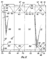
- Figure 11 shows a carton blank designed to produce a carton sleeve for use in the machine hereinbefore described with reference to Figures 1 to 10.
- the blank consists of paperboard coated on both faces with a suitable thermoplastics.
- parallel score lines 130 it is divided into five panels 131 to 135, of which the panel 135 will be heat-and pressure-sealed to the panel 131 to provide a side seam of the carton sleeve 2.
- the panels 131 are divided to form five gable top closure obturating sub-panels 141 to 145, five gable top closure sealing sub-panels 151 to 155 outwardly thereof, five flat bottom closure obturating sub-panels 161 to 165, and five flat bottom closure sealing sub-panels 171 to 175 outwardly thereof.
- Each of the obturating sub-panels 141, 143, 161 and 163 is divided into triangular sub-sub-panels by score lines 146 extending respectively from those two corner regions of the sub-panels nearest to the centre of its panel 131 or 133 to the middle of that side of the sub-panel furthest from the centre of its panel. From the junction of each pair of score lines 146 there extends centrally across the adjacent sealing sub-panel 151, 153, 171 or 173 another score line 147 parallel to the score lines 130 to divide that sealing sub-panel into two rectangular sub-sub-panels.
- the sub-panel 145 is formed with an oblique score line 148 corresponding to one of the score lines 146 of the sub-panel 141.
- the sub-panels-151 and 153 each in a condition folded upon itself about the score lines 147, together with the sub-panel 155, are sandwiched between the sub-panels 152 and 154 and form a sealing fin of the gable top closure.
- the triangular flaps formed by the folded sub-panels 161 and 163 are turned underneath and the in parts 171 and 173 are sealed to the fin parts 172 or 174, thereby to form the flat bottom of the carton.
- the sub-panels 142 and 144 are formed with oblique score lines 149, to facilitate pulling out of the folded sub-panels 143 and 153 to provide the spout.
Abstract

Description
- This invention relates to packaging, particularly to the packaging of liquid, for example milk or orange juice, in cartons.
- It is well known to form carton blanks from paperboard coated on both faces with thermoplastics and to fold and heat-seal the blanks into sleeves. Such sleeves are subsequently supplied in a flat form to a liquid-packaging machine which opens the flat sleeves, folds-in and heat-seals bottom closure sub-panels of the sleeves, fills with liquid the open-topped cartons so produced, and folds-in and heat-seals top closure sub-panels of the cartons. Conventionally, the sleeves and cartons on the machine are indexed, that is to say advanced stepwise, from one operational station to another, but it is more desirable for them to advance continuously, particularly from the point of view of providing a relatively high-speed, and therefore high-output machine. Yet the known designs of carton and of certain machine parts do not lend themselves to such continuous advance.
- United States Patent Specification 3239995 discloses a machine for forming, filling, closing and sealing plastics-coated paperboard cartons in which flat sleeves are successively drawn from a magazine, erected into open-ended tubular form and loaded on to mandrels of a multi-station, indexing, bottom-forming, rotary turret. From the turret, the bottom-closed cartons are conveyed successively along a tubular trackway and then carried by an indexing chain conveyor to top-breaking, filling, top-heating, top-closing and top-sealing stations and then discharged from the machine. The sleeves and cartons are thus indexed through the machine.
- United States Patent Specification 3280531 discloses a somewhat similar machine in which the opened sleeves are indexed along a stationary supporting track by a lifting comb-like structure positioned laterally of the track and having its teeth defining cells receiving the respective sleeves. At a first station, a mandrel is inserted into the sleeve, the top and bottom closure sub-panels are folded-in about horizontal edges of the mandrel and then the mandrel is removed. At a second station, a fin of the bottom closure is heated and, at a third station, the fin is pressure-sealed. At a fourth station, the projecting bottom fin enters a slot of a slidable track component which executes a short movement laterally of the stationary track to displace the fin flatly and in the meantime a press ram enters the open top of the carton and flattens the bottom closure. The carton then proceeds to filling, top-folding, top-heating and top-sealing stations.
- British Patent Specification 1541910 discloses an apparatus for breaking-in, or-out, or both, end sub-panels of a gable top closure of a carton and including two forked breaking elements arranged to embrace from above the respective top edges of the end sealing sub-panels. Insertable into the top of the carton is a disc-like former of a ram, and two opposed stationary guides are located at the outside of the top of the carton. The breaking elements fold the top closure end sub-panels about edges of the former and the guides; both sub-panels are folded inwards about the ram, or both are folded outwards about the respective guides, or one sub-panel is folded inwards about the ram and the other folded outwards about one of the guides. Since the breaking elements perform somewhat reciprocatory motion, they are unsuitable for high-speed operation. Moreover, since the guides extend over only a very small part of the height of the carton, they oppose distortion of the carton over only a very small proportion of its height; in particular, they do not oppose distortion of the carton at its lower end during breaking and folding at that end.
- United States Patent Specification 4,160,406 discloses a compact high speed carton opening and sealing machine and method employing a horizontal flat sleeve feeding mechanism. Sleeves are fed into the opening station, positioned against a stop and vacuum opened from the trailing side panel. The opened horizontal sleeve is maintained in a squared position and driven through the machine by flights mounted on parallel chain conveyors adjustably positioned adjacent the long sides of the sleeve. As the sleeve is driven through the machine, the trailing and leading bottom end flaps are sequentially folded into place and then the bottom side flaps are partially folded into place. With the side flaps in a partially folded position, adhesive is applied to either or both the bottom end flaps and the bottom side flaps. The partially folded side flaps are then maintained in position by a fixed anvil as the carton is delivered by the conveyor to a set of squaring stops. A transversely moving platen then moves the carton laterally to clear the end stops while bringing the end and side flaps into sealing relationship under time and pressure conditions sufficient to effect adhesion between the side and end flaps. Thereafter, the sealed carton is ejected from the machine by the movement of the succeeding carton into the sealing station. The vacuum opening of the sleeve is performed by two vacuum cups applied to the lower side panel of the sleeve and to the trailing side panel, respectively, the cup applied to the latter panel being turned, relative to the other cup, about an axis parallel to but spaced inwards from the natural axis of turning of the trailing side panel relative to the lower side panel. This has the disadvantage of risking distortion of the sleeve, or slipping of the turning vacuum cup relative to the trailing side panel.
- According to one aspect of the present invention, there is provided a method of opening a sleeve of polygonal cross-section, comprising applying first and second suction members to respective first and second walls of the sleeve and causing the first and second walls to adhere to said members by suction, and moving the first suction member relative to the second suction member along a path to open said sleeve, characterized in that said path corresponds to a natural path of movement of the first wall relative to the second wall.
- According to a second aspect of the present invention, there is provided apparatus for opening a sleeve of polygonal cross-section, comprising first and second suction members applicable to respective first and second walls of the sleeve, suction-producing means arranged to produce suction in said members to cause the first and second walls to adhere to said members by suction, means mounting the first suction member for movement relative to the second suction member along a path to open said sleeve, and drive means arranged to drive said first suction member along said path, characterized in that said path corresponds to a natural path of movement of the first wall relative to the second wall
- Moving of the first suction member relative to the second suction member along a natural path of movement of the first wall relative to the second wall reduces any risk of distortion of the sleeve or slipping of the suction members on the walls.
- According to a third aspect of the present invention, there is provided a method of producing a container containing a substance, including bringing bottom parts of said container together, and sealing said bottom parts together to form a bottom closure of said container, characterized in that substantially simultaneously with said sealing, said substance is filled into said container.
- According to a fourth aspect of the present invention, there is provided apparatus for use in producing a container containing a substance, including means for bringing bottom parts of said container together and sealing said bottom parts together to form a bottom closure of said container, and filling means arranged to fill said substance into said container, characterized in that said filling means is arranged to fill said substance into said container substantially simultaneously with said sealing.
- Filling of the container substantially simultaneously with the bottom sealing has the advantage of permitting reduction of the total time taken for any one container to undergo the packaging process.
- According to a fifth aspect of the present invention, there is provided a method of conveying articles comprising advancing said articles to a transfer location in respective pockets of a first conveyor closely receiving said articles but each open at one lateral side of the path of said articles, and operating a second conveyor transversely of the first conveyor to strip the articles from the respective pockets in the sense of said one lateral side, characterized in that the first and second conveyors continuously advance and the articles slide transversely of the second conveyor while being stripped from the pockets.
- According to a sixth aspect of the present invention, there is provided apparatus for conveying articles, comprising a first conveyor arranged to advance articles to a transfer location in respective pockets of said conveyor closely receiving said articles but each open at one lateral side of the path of said articles, and a second conveyor arranged transversely of said first conveyor to strip the articles from the respective pockets in the sense of said one lateral side, characterized in that the first and second conveyors are arranged to advance continuously and the second conveyor is such that the articles being advanced thereby can slide transversely thereof.
- In this way, the articles move continuously through the apparatus.
- According to a seventh aspect of the present invention, there is provided a method of producing a carton containing a substance, including causing said carton to be closely constrained externally by wall means at respective opposite sides of the carton, and breaking end closure sub-panels of said carton at said respective opposite sides by turning said sub-panels outwardly about said wall means, characterized in that said breaking is performed by a continuous-motion breaking device.
- According to an eighth aspect of the present invention, there is provided apparatus for use in producing a carton containing a substance, comprising wall means for closely constraining said carton externally at respective opposite sides thereof, and breaking means for turning end closure sub-panels of said carton at said respective opposite sides outwardly about said wall means to break said sub-panels, characterized in that said breaking means is a continuous-motion breaking means.
- The use of continuous-motion breaking means has the advantage of facilitating high-speed breaking. The external wall means advantageously extends over a considerable part of the length of the carton during breaking, preferably over the whole length of the main sub-panels of the carton, i.e. the whole spacing between the top closure and the bottom closure, in order to increase the opposition to distortion of the carton.
- According to a ninth aspect of the present invention, there is provided a carton comprising first, second, third and fourth panels arranged in a loop around said carton, lines of weakness extending around said carton and thereby dividing said panels into loops of sub-panels including a loop of first, second, third and fourth top closure sealing sub-panels forming a sealing fin of a top closure, a loop of first, second, third and fourth top closure obturating sub-panels adjacent the row of sealing sub-panels, a loop of first, second, third and fourth bottom closure sealing sub-panels forming a sealing fin of a bottom closure, and a loop of first, second, third and fourth bottom closure obturating sub-panels adjacent the loop of bottom closure sealing sub-panels, further lines of weakness dividing the first and third bottom closure obturating sub-panels into substantially triangular sub-sub-panels, characterized in that the top closure is a gable top closure, the bottom closure is a flat bottom closure, and the said triangular sub-sub-panels lie at the outside of the second and fourth flat bottom closure obturating sub-panels.
- This carton is particularly suitable for continuous advance in high-speed packaging.
- In order that the invention may be clearly understood and readily carried into effect, reference will now be made, by way of example, to the accompanying drawings, in which:-
- Figure 1 shows a diagrammatic top plan view of a packaging machine for producing cartons filled with liquid,
- Figure 2 shows a diagrammatic fragmentary side elevation of the machine,
- Figure 3 shows a detail of Figure 1, in particular of a feeder for flat, carton sleeves,
- Figure 4 shows a section taken on the line IV-IV of Figure 3,
- Figure 5 shows another detail of Figure 1, in this case of part of a carton sleeve opening turret,
- Figure 6 shows a section taken on the lines VI-VI of Figure 5,
- Figure 7 shows a detail of Figure 2, in this case of a top pre-breaker turret,
- Figure 8 shows a fragmentary top plan view of the top pre-breaker turret,
- Figure 9 shows a fragmentary elevation taken in the direction of the arrow IX in Figure 7,
- Figure 10 shows another detail of Figure 2, and
- Figure 11 shows a plan view of a carton blank from which a flat carton sleeve is to be formed.
- Referring to the drawings, particularly to Figures 1 and 2, the packaging machine is designed for high-speed packaging of liquid, for example milk or orange juice, in gable-topped cartons. It can attain a speed of at least 300 cartons per minute. It includes a feeder 1 for feeding
flat carton sleeves 2 to a rotary sleeve-openingturret 3, which feeds the sleeves intochain pockets 4 of a continuously advancingendless conveyor chain 5 as thechain 5 passes around a rotary top pre-breaker turret 6. Eachsleeve 2 has been made from a blank (shown in Figure 11) consisting of paperboard coated on both faces with a suitable thermoplastics. Thepockets 4 are so designed that they closely receive thesleeves 2 with the sleeves in a fully opened, rectangular condition, the three upright walls of the pockets, and a fixed vertical guide wall along which the open side of eachpocket 4 moves, substantially preventing movement of the sleeve relative to the pocket in any horizontal direction. A rotary horizontal supporting plate 7 of the turret 6 prevents thesleeves 2 from falling out of thepockets 4. Thechain 5 advances thesleeves 2 along a fixed horizontal supporting plate 71 to over a bottom pre-breaker 8, by which bottom closure sub-panels of each carton are pre-broken along score lines, the walls of thepocket 4 and the vertical guide wall acting effectively as an encircling mandrel for maintaining the general rectangular shape of the remainder of the sleeve during this bottom pre-breaking. Thechain 5 forwards thesleeves 2 from the pre-breaker 8 to a pair of bottom closure ploughing-in
andguide rails 9, which force towards each other lateral sub-panels of the bottom closure and which guide them in a partially open condition over abottom heater 10 which blows hot air upwards into the bottom closure, so rendering tacky the internal thermoplastics coating thereof, Thechain 5 advances thesleeves 2 along therails 9, which at their farther ends plough-in the lateral bottom closure sub-panels to a condition in which lateral sealing sub-panels thereof are virtually in contact with each other, whereupon thechain 5 forwards eachsleeve 2 to a lead-inblock 11 which is vertically slotted to receive the bottom sealing sub-panels and lead them into a pair ofpre-sealing nip rollers 12. Thechain 5 advances the carton 2' so formed to a rotary filling and bottom-sealing turret 13, in which the bottom closure sealing sub-panels are held together for a relatively long time to give good sealing, and the liquid is filled into the carton which, since the liquid is cool, also assists sealing. A carton being bottom-sealed in indicated at 2' in Figure 1 from which it will be noted that triangular parts of the bottom closure thereof project below the walls of thepocket 4. Thechain 5 passes around this turret and forwards the filled cartons to atop tucker 14, from which the chain carries the cartons along between a pair of top closure ploughing-in andguide rails 15, above which is atop heater 16 which blows hot air downwards onto top closure sub-panels of the carton to render tacky the thermoplastics coatings thereof. Thechain 5 advances the cartons from thetop heater 16 to atop sealer 17 consisting of a pair of horizontalendless chains 18 each provided with a series of horizontal sealing jaws 19. The jaws 19 of the twochains 18 come together in pairs to grip between them gable top closure sealing sub-panels of the carton to form the gable top closure sealing fin. Thechain 5 advances the sealed cartons to a transfer location at which a continuously advancingconveyor 20 strips the sealed cartons from the continuously advancingchain 5. Theconveyor 20 consists of twoendless chains chain 21 being arranged above thechain 5 and thechain 22 being arranged below the same. Each of thechains slats 23 extending parallely to theconveyor 5, the lower run of thechain 21 and the upper run of thechain 22 moving in the same direction as each other, namely horizontally perpendicularly outwards of the return run of thechain 5. Theslats 23 of the lower run of thechain 21 and theslats 23 of the upper run of thechain 22 come to bear against the respective top and bottom fins of the cartons 2' arriving at the transfer station and thereby push laterally outwards the cartons in the respective chain pockets 4, although thechain 5 continues to push the cartons towards the turret 6, which it can do because theslats 23 allow sliding of the cartons transversely of theconveyor 20. Theconveyor 20, which is relatively short, moves at the same speed as a secondtransverse conveyor 24, which again consists of a pair of upper and lowerendless chains slats 27. The action of thechain 5 causes the cartons to slide from between their respective pairs ofslats 23 to between their respective pairs ofslats 27, by which they are displaced to asecond bottom heater 28 which renders tacky the thermoplastics coating of the downwardly directed outside faces of the sub-panels of the bottom closure, and thence to a tucking-indevice 29 for tucking inwards triangular end flaps of the bottom closure and retaining those flaps in a tucked-in condition whilst they seal against underneath surface portions of the bottom closure. Referring to Figure 3, the feeder 1 includeshorizontal guide rails 30 for theflat sleeves 2, a pack of flat sleeves 2 (not shown) being advanced stepwise by pressingfingers 31 mounted on respective slide blocks 32 themselves guided onrespective guide rods 33. Theblocks 32 are advanced stepwise in synchronism byrespective drive chains 34. At the exit from the guide rails 3(1, thesleeves 2 are supported by ahorizontal rail 35 and are there stripped one-by-one from the end of the pack by a lug (not shown) provided on a horizontal endless conveyingchain 36. The lug pushes the stripped sleeve into a nip between a drivenroller 37 and anidler roller 38. Therollers roller device 40 shown in more detail in Figure 4. Thedevice 40 includes avertical shaft 41 to the upper end of which is fixed aradial arm 42 which at its forked outer end is provided with adouble roller arrangement 43 which is embraced by the forked outer end of thearm 42 and which is guided for movement in the fork by means of ahorizontal stud 44 fixed thereto. Theroller arrangement 43 is urged outwardly by ahelical compression spring 45 encircling thestud 44 and is limited as to its outward movement by nuts 4C on thestud 44. With thesleeve 2 in position against thesuction pad 39, theshaft 41 swings theroller arrangement 43 to a position in which it presses thesleeve 2 against thesuction pad 39 and at the same time causes thesleeve 2 to depress and thus open avalve closure member 47 of a valve 48 of thepad 39. - Referring to Figures 5 and 6 the sleeve opening turret 6 comprises a fixed, vertical
central axle 50 to the upper end of which is keyed ahorizontal cam plate 51 formed with acontinuous camming slot 52. Vertically through the centre of theaxle 50 extends avacuum line 53 which terminates at its upper end in adistributor valve 54, a rotaryupper part 55 of which is connected viarespective suction tubes 56 to thesuction pads 39. Mounted for rotation about theaxle 50 is a co-axialtubular body 57 which is driven at atoothed ring 68 and to which therotary part 55 is attached by astrap 58. Thebody 57 has thesuction pads 39 distributed around the wider, upper part thereof. Arranged on thebody 57 adjacent to therespective pads 39 are eight crankedsuction brackets 59 each provided with threesmall suction pads 60. Eachpad 60 issimilar toeach pad 39 in incorporating a valve openable by depression of its valve closure member by contact with aflat sleeve 2. Eachbracket 59 is swingable about a vertical axis invertical bearings 61 mounted in respectivehorizontal flanges 69 of the wider upper part of thebody 57. Just below thelower bearing 61, eachbracket 59 has fixed thereto apinion 62 of a rack-and-pinion device rack 63 is fixed to aslide bar 64 guided in thebody 57 and mounting at its inner end aroller follower 65 which runs in theslot 52. Eachtube 56 has abranch duct 66 therefrom leading via a connector 67 to the upper end of thebracket 59, most of which is hollow so that suction can be applied to thepads 60. - In operation of the sleeve-opening turret 3, the continuously rotating turret brings the sleeve 2 from a position shown at a in Figure 1, in which one of two adjacent panels of the flat sleeve are held by suctio:. against one of the suction pads 39, through a position b in which the adjacent bracket 59 has been swung to bring its suction pads 60 against the other of those two panels and in which that other panel is held against the pads 60 by suction, through a position c in which the bracket 59 has been swung about its axis of turning, which coincides with the junction line between those two panels, partially to open the sleeve to a cross-section of diamond shape as shown, (since the axis of turning of the bracket 59 coincides with the junction line, the pads 60 of the bracket 59 move along an arcuate path corresponding to the natural path of movement of that other panel relative to that one panel), through a position d, in which the bracket 59 has continued to turn and brought the sleeve to a condition in which its cross-section is rectangular, and through a position e in which the bracket 59 has continued to turn in order partially to close the sleeve to bring it again to a condition in which its cross-section is of a diamond shape, to a position f in which the sleeve is again of a rectangular cross-section, as at d, and is closely received in a chain pocket 4, the bracket 59 having turned back to its angular position shown at d, the gradual change in shape of the sleeve cross-section from e to f enabling the sleeve to be fitted closely into the pocket 4 with substantially no distortion of the sleeve, because the linear speed of the suction cups 39 and 60 holding the sleeves 2 is made to he higher than that of the chain pockets 4.
- Referring to Figures 7 to 9, the top pre-breaker turret 6 comprises a plurality of
top pre-breakers 70 equi-angularly spaced around the turret 6 and arranged to coincide in vertical alignment with the chain pockets 4 as these latter move around the turret 6. The turret comprises a fixed vertical central axle 71 on which is mounted arotary body 72 carrying the pre-breakers 70. Encircling the axle 71 is a fixedsleeve 73 formed with a continuous externalperipheral camming slot 74. In theslot 74 there runs aroller follower 75 attached to the lower end of a reciprocatoryvertical rod 76 which is guided in linear bearings 77 in thebody 72, Encircling the upper part of therod 76 is a sleeve 78 in which therod 76 is mounted by way oflinear bearings 79. Ahelical compression spring 80 acts between anannular washer 81 supported by an upwardly facing internal shoulder of the sleeve 78 and aflanged bush 82 encircling and retained on the upper end of therod 76. The sleeve 78 is attached to avertical slide 83 mounted in avertical guide 84 forming part of thebody 72. Also attached to the sleeve 78 is a radially outwardly projectingbracket 85 supporting, at respective lateral sides thereof,respective bearings 86 mounting respective crankedshafts 87 havingrespective pinions 88 fixed to the inner ends thereof. Thepinions 88 mesh with respectivevertical racks 89 fixed to respective opposite sides of therod 76. The crank in eachshaft 87 is located radially outwardly of itsbearing 86 and, at its radially outer end eachshaft 87 has fixed thereto atriangular flap 93 for pre-breaking top closure sub-panels of thesleeves 2. Between the outer ends oi theshafts 87 there is located an internal anvil consisting of ahorizontal plate 90 with a downwardly taperingskin 91. - In operation, as each pre-breaker 70 moves around the axle 71 with the aligned
pocket 4 containing asleeve 2, itsfollower 75 lowers therod 76 from its uppermost position shown in full lines in Figure 8 into its lowermost position 76' shown in dot-dash lines in that Figure. Near the end of this downward stroke of therod 76, the sleeve 78 strikes ahardened abutment 92 on thebody 72. This occurs when the topmost surface of theinternal anvil rod 76, now relative to the sleeve 78 and against the action of thespring 80, causes theracks 89 to rotate thepinions 88 to bring thetriangular flaps 93 from the full-line condition shown in Figure 9 for one of the flaps and one of theshafts 87 to the condition shown in dot-dash lines 87' and 93'in that Figure, thereby to pre-break the top closure sub-panels of thesleeve 2. Then thefollower 75 lifts therod 76 back into its uppermost position, so initially turning theflaps 93 andtht shafts 87 back into the upright full-line positions for theflaps 93 shown in Figure 9 and thereafter raising the sleeve 78 into its position shown in Figure 8, thereby lifting theanvil sleeve 2. - The
items pre-breaker wheel 95 which rotates continuously in the sense of the arrow A. Thewheel 95 is in the form of a vertical plate formed with four trapezium-shapedlobes 96 equi-angularly spaced about the axis of the wheel. Thewheel 95 is fixed to arotary driving flange 97 by means of bolts 98 (of which only one is shown) passing throughholes 99 in thewheel 95, which holes are arcuate in order to allow for an accurate pre-setting of the angular position of thewheel 95 relative to theflange 97. As eachsleeve 2 arrives above thewheel 95, one of the lobes 9G enters the open bottom of the sleeve and the leading face of thatlobe 96 displaces forwards the leading sub-panels of the bottom closure of thesleeve 2 and its lagging face displaces rearwards the lagging sub-panels of that bottom closure. While this is being done, the three walls of therelevant pocket 4, together with the fixed vertical guide wall closing the open side of thepocket 4, which wall is co-extensive with the pocket walls insofar as its vertical dimension is concerned, act as an external mandrel for this bottom pre-breaking, the bottoms of the walls for this purpose being arrraged at the level of the tops of obturating sub-panels of the bottom closure. - The bottom closure sub-panels are now immediately received between the
rails 9 which are arranged at approximately the level of boundaries between sealing sub-panels, on the one hand, and the obturating sub-panels, on the other hand, of the bottom closure. These rails initially converge and thus they plough-in, in other words swing towards each other, the lateral sub-panels of the bottom closure whereby the leading and lagging sub-panels thereof are swung increasingly away from one another. As therails 9 approach theheater 10, they begin to run parallely to each other, so that the ploughing-in effect ceases. The heater includes aheater box 100 extending along beneath thechain 5 and of a rectangular cross-section, as shown at 100', with a hotair outlet slot 101 formed centrally through the top wall thereof. Immediately above theslot 101 and effectively narrowing the mouth thereof is a pair ofparallel guide rails 102 extending the length of thebox 100. The guide rails 9 and 102 are each of a tubular form and are cooled by passing cooling liquid through their interiors. The arrangement is such that the lowermost extremities of thesleeve 2 slide along theguide rails 102 so that most of the hot air applied through theslot 101 to the bottom closure sub-panels is applied to the insides of those panels and renders tacky the thermoplastics coatings of those insides, particularly of the bottom closure sealing sub-panels, which are in fact nearest tu theslot 101. Hot air is supplied to thebox 100 from a heater blower lC3 via asupply pipe 104 and aflap valve 105. Theflap 106 of thevalve 105 is movable by anoperating ram 107 between its position shown in chain lines in Figure 10 in which the hot air flows into thebox 100, and its position shown in dot-dash lines in Figure 10, in which the hot air is diverted to anexhaust pipe 108 and into which theflap 106 is moved automatically whenever thechain 5 is stopped, in order to avoid overheating of thesleeves 2. At their farther end, therails 9 converge upwardly towards each other, as indicated at 9', and thereby force the bottom closure sub-panels further inwards towards each other. As the bottom closure sealing sub-panels leave therails 9 they enter a convergingportion 109 of the vertical slot in theblock 11. The convergingportion 109 merges into a parallel-sided portion 110, in which the sealing sub-panels are face-to-face with each other. - The filling and bottom-sealing turret 13 will now be described with reference tc Figures 1 and 2. The turret includes a plurality of reciprocatory bellows
fillers 111 which rotate around the vertical axis of the turret in vertical alignment with the chain pockets 4 as these proceed around the turret. Thefillers 111 are supplied with cool liquid, such as milk or orange juice, from atank 112 rotating with them. Eachfiller 111 has there- above apneumatic ram 113 for operating the same. Arranged vertically below therespective fillers 111 are respectivebottom closure sealers 114. Eachsealer 114 includes a pair of clampingjaws jaw 115 is fixed relative to therotary body 117 of the turret 13, and of which thejaw 116 is movable radially of theturret 113 relative to thejaw 115 by means of aroller follower 118 running in anannular camming slot 119 in acamming plate 120 fixed relative to the frame of the machine. Thechain 5 carries the bottom pre-sealed carton from therollers 12 to between a pair ofjaws filler 111 meanwhile filling the carton with the cool liquid from thetank 112.. In the open condition, thejaws - The
chain 5 then carries the filled carton 2' to thetop tucker 14 which includes a plate-form wheel 121 including fourlegs 122 terminating outwardly in a foot having a forwardly projectingtoe 123 and arearwardly projecting heel 124. The speed of turning of thewheel 121 relative to the speed of advance of thechain 5 is such that each filled carton 2' catches up with aheel 124 of oneleg 122 and thus the leading sub-panels oi the top closure are pushed firmly in between the lateral sub-panels thereof,and then thetoe 123 of thenext leg 122 catches up with the carton and thus the lagging sub-panels of the carton are pushed firmly in between the lateral sub-panels thereof. The provision of thetucker 14 ensures that any leading or lagging sub-panels which have moved out of their desired positions between the lateral sub-panels since pre-breaking at the turret 6 are brought back into their desired positions. Thetop heater 16 will not be described in detail since it is similar to thebottom heater 10, including aheater box 125, aflap valve 126, asupply pipe 127, aheater blower 128, and anexhaust pipe 129. - Figure 11 shows a carton blank designed to produce a carton sleeve for use in the machine hereinbefore described with reference to Figures 1 to 10. The blank consists of paperboard coated on both faces with a suitable thermoplastics. By means of
parallel score lines 130 it is divided into fivepanels 131 to 135, of which thepanel 135 will be heat-and pressure-sealed to thepanel 131 to provide a side seam of thecarton sleeve 2. By means ofscore lines 136 to 139 perpendicular to the score lines 130, thepanels 131 are divided to form five gable topclosure obturating sub-panels 141 to 145, five gable topclosure sealing sub-panels 151 to 155 outwardly thereof, five flat bottomclosure obturating sub-panels 161 to 165, and five flat bottomclosure sealing sub-panels 171 to 175 outwardly thereof. Each of the obturating sub-panels 141, 143, 161 and 163 is divided into triangular sub-sub-panels byscore lines 146 extending respectively from those two corner regions of the sub-panels nearest to the centre of itspanel score lines 146 there extends centrally across theadjacent sealing sub-panel score line 147 parallel to thescore lines 130 to divide that sealing sub-panel into two rectangular sub-sub-panels. The sub-panel 145 is formed with anoblique score line 148 corresponding to one of thescore lines 146 of thesub-panel 141. In the sealed carton 2' produced from thecarton sleeve 2, the sub-panels-151 and 153, each in a condition folded upon itself about the score lines 147, together with the sub-panel 155, are sandwiched between the sub-panels 152 and 154 and form a sealing fin of the gable top closure. Moreover, each of the sub-panels 171 and 173 folded upon itself about itsscore line 147, but with the sub-panel 175 between the rectangular sub-sub-panels of the sub-panel 173, is sealed face-to-face upon itself, whilst the sub-panels 172 and 174 are sealed together face-to-face, thereby providing a sealing fin appreciably longer than the width of the widest of thepanels 131 to 135, this latter sealing fin being turned back upon the sub-panels 161 to 164. The triangular flaps formed by the folded sub-panels 161 and 163 are turned underneath and the inparts fin parts oblique score lines 149, to facilitate pulling out of the folded sub-panels 143 and 153 to provide the spout.
Claims (23)
Priority Applications (1)
| Application Number | Priority Date | Filing Date | Title |
|---|---|---|---|
| AT83304610T ATE34137T1 (en) | 1982-08-09 | 1983-08-09 | PACKAGING. |
Applications Claiming Priority (2)
| Application Number | Priority Date | Filing Date | Title |
|---|---|---|---|
| GB8222936 | 1982-08-09 | ||
| GB8222936 | 1982-08-09 |
Publications (3)
| Publication Number | Publication Date |
|---|---|
| EP0112605A2 true EP0112605A2 (en) | 1984-07-04 |
| EP0112605A3 EP0112605A3 (en) | 1985-11-13 |
| EP0112605B1 EP0112605B1 (en) | 1988-05-11 |
Family
ID=10532207
Family Applications (1)
| Application Number | Title | Priority Date | Filing Date |
|---|---|---|---|
| EP83304610A Expired EP0112605B1 (en) | 1982-08-09 | 1983-08-09 | Packaging |
Country Status (4)
| Country | Link |
|---|---|
| EP (1) | EP0112605B1 (en) |
| JP (2) | JPS59187524A (en) |
| AT (1) | ATE34137T1 (en) |
| DE (1) | DE3376550D1 (en) |
Cited By (7)
| Publication number | Priority date | Publication date | Assignee | Title |
|---|---|---|---|---|
| WO2006029795A1 (en) * | 2004-09-17 | 2006-03-23 | Sig Technology Ag | Device and method for sealing filled cardboard/plastic composite packaging by means of ultrasound |
| WO2014187592A1 (en) | 2013-05-23 | 2014-11-27 | Sig Technology Ag | Device and method for folding open packaging sleeves |
| DE102013107223A1 (en) | 2013-07-09 | 2015-01-15 | Sig Technology Ag | Device and method for unfolding, filling and sealing of pack coats |
| DE102014102333A1 (en) | 2014-02-24 | 2015-08-27 | Sig Technology Ag | Apparatus and method for prefolding package coats |
| WO2019232254A1 (en) * | 2018-05-30 | 2019-12-05 | Evergreen Packaging, Inc. | Carton squaring clamp, process of forming a gable top carton and gable top carton filling machine |
| CN112429319A (en) * | 2020-12-03 | 2021-03-02 | 广东省智能机器人研究院 | Automatic folding mechanism |
| WO2023197680A1 (en) * | 2021-08-20 | 2023-10-19 | 青岛吉凯乐包装有限公司 | Bottom sealing apparatus and process for folding packaging container |
Families Citing this family (1)
| Publication number | Priority date | Publication date | Assignee | Title |
|---|---|---|---|---|
| JP5772507B2 (en) * | 2011-10-27 | 2015-09-02 | 大日本印刷株式会社 | Paper container and blank |
Citations (3)
| Publication number | Priority date | Publication date | Assignee | Title |
|---|---|---|---|---|
| US3280531A (en) * | 1962-06-22 | 1966-10-25 | Jagenberg Werke Ag | Method and apparatus for the manufacture, filling and closing of liquidtight containers |
| NL7212324A (en) * | 1971-11-12 | 1973-05-15 | ||
| US4018143A (en) * | 1975-05-02 | 1977-04-19 | Cal Crown Corporation | Cardboard box erecting machine |
Family Cites Families (5)
| Publication number | Priority date | Publication date | Assignee | Title |
|---|---|---|---|---|
| JPS5930474B2 (en) * | 1977-06-15 | 1984-07-27 | 日立造船株式会社 | Fruit sorting device |
| JPS54135097A (en) * | 1978-04-11 | 1979-10-19 | Rengo Co Ltd | Device for automatically setting up box of arbitrary dimensions |
| JPS5543041U (en) * | 1978-09-16 | 1980-03-19 | ||
| JPS601202B2 (en) * | 1979-11-02 | 1985-01-12 | 四国化工機株式会社 | packaging machinery |
| JPS578604A (en) * | 1980-06-14 | 1982-01-16 | Ace Pack Kk | Treating device for lug section of flat top type carton |
-
1983
- 1983-08-09 AT AT83304610T patent/ATE34137T1/en not_active IP Right Cessation
- 1983-08-09 DE DE8383304610T patent/DE3376550D1/en not_active Expired
- 1983-08-09 EP EP83304610A patent/EP0112605B1/en not_active Expired
- 1983-08-09 JP JP58144531A patent/JPS59187524A/en active Pending
-
1992
- 1992-06-22 JP JP049542U patent/JPH0592109U/en active Pending
Patent Citations (3)
| Publication number | Priority date | Publication date | Assignee | Title |
|---|---|---|---|---|
| US3280531A (en) * | 1962-06-22 | 1966-10-25 | Jagenberg Werke Ag | Method and apparatus for the manufacture, filling and closing of liquidtight containers |
| NL7212324A (en) * | 1971-11-12 | 1973-05-15 | ||
| US4018143A (en) * | 1975-05-02 | 1977-04-19 | Cal Crown Corporation | Cardboard box erecting machine |
Cited By (12)
| Publication number | Priority date | Publication date | Assignee | Title |
|---|---|---|---|---|
| WO2006029795A1 (en) * | 2004-09-17 | 2006-03-23 | Sig Technology Ag | Device and method for sealing filled cardboard/plastic composite packaging by means of ultrasound |
| WO2014187592A1 (en) | 2013-05-23 | 2014-11-27 | Sig Technology Ag | Device and method for folding open packaging sleeves |
| DE102013105260A1 (en) | 2013-05-23 | 2014-11-27 | Sig Technology Ag | Apparatus and method for unfolding package coats |
| DE102013107223A1 (en) | 2013-07-09 | 2015-01-15 | Sig Technology Ag | Device and method for unfolding, filling and sealing of pack coats |
| DE102013107223B4 (en) * | 2013-07-09 | 2017-12-07 | Sig Technology Ag | Device and method for unfolding, filling and sealing of pack coats |
| DE102014102333A1 (en) | 2014-02-24 | 2015-08-27 | Sig Technology Ag | Apparatus and method for prefolding package coats |
| WO2015124396A1 (en) | 2014-02-24 | 2015-08-27 | Sig Technology Ag | Apparatus and method for pre-folding open packaging sleeves |
| CN106458342A (en) * | 2014-02-24 | 2017-02-22 | Sig技术股份公司 | Apparatus and method for pre-folding open packaging sleeves |
| WO2019232254A1 (en) * | 2018-05-30 | 2019-12-05 | Evergreen Packaging, Inc. | Carton squaring clamp, process of forming a gable top carton and gable top carton filling machine |
| TWI804629B (en) * | 2018-05-30 | 2023-06-11 | 美商唯綠包裝公司 | Apparatus and process for forming a gable top seal |
| CN112429319A (en) * | 2020-12-03 | 2021-03-02 | 广东省智能机器人研究院 | Automatic folding mechanism |
| WO2023197680A1 (en) * | 2021-08-20 | 2023-10-19 | 青岛吉凯乐包装有限公司 | Bottom sealing apparatus and process for folding packaging container |
Also Published As
| Publication number | Publication date |
|---|---|
| JPH0592109U (en) | 1993-12-14 |
| JPS59187524A (en) | 1984-10-24 |
| EP0112605B1 (en) | 1988-05-11 |
| DE3376550D1 (en) | 1988-06-16 |
| ATE34137T1 (en) | 1988-05-15 |
| EP0112605A3 (en) | 1985-11-13 |
Similar Documents
| Publication | Publication Date | Title |
|---|---|---|
| US3461642A (en) | Method and machine for forming and sealing a carton | |
| US3716962A (en) | Carton flap folding mechanism | |
| US3340679A (en) | Apparatus for opening pouches | |
| US4802324A (en) | Vertical cartoning assembly and method | |
| US4578054A (en) | Carton erection and sealing apparatus | |
| US3855907A (en) | Method and machine for forming flat bottom bags having side gussets | |
| JPH0311132Y2 (en) | ||
| US3956868A (en) | Carton opening, filling and closing apparatus | |
| US4918906A (en) | Method and apparatus for producing a bag-in-carton | |
| JPH04242503A (en) | Method and device to package article | |
| CA1094374A (en) | Method and apparatus for erecting a carton | |
| CN112623356A (en) | Glove box packing production line | |
| MX2007009673A (en) | Machine for automated packaging of product(s) in a cardboard box. | |
| CA1288269C (en) | High capacity continuous package seam and tab folding and tacking apparatus and method | |
| EP0112605B1 (en) | Packaging | |
| US5588279A (en) | Apparatus and method for transporting a container between processing stations of a packaging machine | |
| CN216401899U (en) | Food packaging machinery and envelope device | |
| NO141505B (en) | PROCEDURE AND MACHINE FOR SHAPING A CONTAINER BLANK TO A TUBE-SHAPED BODY | |
| US3187483A (en) | Carton sealing apparatus | |
| EP0079560A1 (en) | Forming, filling and sealing machine | |
| US3302365A (en) | Packaging machine and method | |
| US4063983A (en) | Orbital heat sealing apparatus and method | |
| US3733980A (en) | Carton gluing machine and method | |
| GB2233954A (en) | Machines for packing sets of articles | |
| CN114401898B (en) | Device and method for forming containers by folding |
Legal Events
| Date | Code | Title | Description |
|---|---|---|---|
| PUAI | Public reference made under article 153(3) epc to a published international application that has entered the european phase |
Free format text: ORIGINAL CODE: 0009012 |
|
| AK | Designated contracting states |
Designated state(s): AT BE CH DE FR GB IT LI NL SE |
|
| PUAL | Search report despatched |
Free format text: ORIGINAL CODE: 0009013 |
|
| AK | Designated contracting states |
Designated state(s): AT BE CH DE FR GB IT LI NL SE |
|
| 17P | Request for examination filed |
Effective date: 19860513 |
|
| 17Q | First examination report despatched |
Effective date: 19861103 |
|
| GRAA | (expected) grant |
Free format text: ORIGINAL CODE: 0009210 |
|
| AK | Designated contracting states |
Kind code of ref document: B1 Designated state(s): AT BE CH DE FR GB IT LI NL SE |
|
| REF | Corresponds to: |
Ref document number: 34137 Country of ref document: AT Date of ref document: 19880515 Kind code of ref document: T |
|
| REF | Corresponds to: |
Ref document number: 3376550 Country of ref document: DE Date of ref document: 19880616 |
|
| ITF | It: translation for a ep patent filed |
Owner name: SOCIETA' ITALIANA BREVETTI S.P.A. |
|
| ET | Fr: translation filed | ||
| PLBE | No opposition filed within time limit |
Free format text: ORIGINAL CODE: 0009261 |
|
| STAA | Information on the status of an ep patent application or granted ep patent |
Free format text: STATUS: NO OPPOSITION FILED WITHIN TIME LIMIT |
|
| 26N | No opposition filed | ||
| ITTA | It: last paid annual fee | ||
| EAL | Se: european patent in force in sweden |
Ref document number: 83304610.5 |
|
| PGFP | Annual fee paid to national office [announced via postgrant information from national office to epo] |
Ref country code: FR Payment date: 20000719 Year of fee payment: 18 |
|
| PGFP | Annual fee paid to national office [announced via postgrant information from national office to epo] |
Ref country code: SE Payment date: 20000720 Year of fee payment: 18 Ref country code: GB Payment date: 20000720 Year of fee payment: 18 Ref country code: DE Payment date: 20000720 Year of fee payment: 18 |
|
| PGFP | Annual fee paid to national office [announced via postgrant information from national office to epo] |
Ref country code: CH Payment date: 20000721 Year of fee payment: 18 Ref country code: AT Payment date: 20000721 Year of fee payment: 18 |
|
| PGFP | Annual fee paid to national office [announced via postgrant information from national office to epo] |
Ref country code: NL Payment date: 20000724 Year of fee payment: 18 |
|
| PGFP | Annual fee paid to national office [announced via postgrant information from national office to epo] |
Ref country code: BE Payment date: 20000809 Year of fee payment: 18 |
|
| PG25 | Lapsed in a contracting state [announced via postgrant information from national office to epo] |
Ref country code: GB Free format text: LAPSE BECAUSE OF NON-PAYMENT OF DUE FEES Effective date: 20010809 Ref country code: AT Free format text: LAPSE BECAUSE OF NON-PAYMENT OF DUE FEES Effective date: 20010809 |
|
| PG25 | Lapsed in a contracting state [announced via postgrant information from national office to epo] |
Ref country code: SE Free format text: LAPSE BECAUSE OF NON-PAYMENT OF DUE FEES Effective date: 20010810 |
|
| PG25 | Lapsed in a contracting state [announced via postgrant information from national office to epo] |
Ref country code: LI Free format text: LAPSE BECAUSE OF NON-PAYMENT OF DUE FEES Effective date: 20010831 Ref country code: CH Free format text: LAPSE BECAUSE OF NON-PAYMENT OF DUE FEES Effective date: 20010831 Ref country code: BE Free format text: LAPSE BECAUSE OF NON-PAYMENT OF DUE FEES Effective date: 20010831 |
|
| BERE | Be: lapsed |
Owner name: LIQUIPAK INTERNATIONAL B.V. Effective date: 20010831 |
|
| PG25 | Lapsed in a contracting state [announced via postgrant information from national office to epo] |
Ref country code: NL Free format text: LAPSE BECAUSE OF NON-PAYMENT OF DUE FEES Effective date: 20020301 |
|
| EUG | Se: european patent has lapsed |
Ref document number: 83304610.5 |
|
| GBPC | Gb: european patent ceased through non-payment of renewal fee |
Effective date: 20010809 |
|
| REG | Reference to a national code |
Ref country code: CH Ref legal event code: PL |
|
| PG25 | Lapsed in a contracting state [announced via postgrant information from national office to epo] |
Ref country code: FR Free format text: LAPSE BECAUSE OF NON-PAYMENT OF DUE FEES Effective date: 20020430 |
|
| NLV4 | Nl: lapsed or anulled due to non-payment of the annual fee |
Effective date: 20020301 |
|
| PG25 | Lapsed in a contracting state [announced via postgrant information from national office to epo] |
Ref country code: DE Free format text: LAPSE BECAUSE OF NON-PAYMENT OF DUE FEES Effective date: 20020501 |
|
| REG | Reference to a national code |
Ref country code: FR Ref legal event code: ST |