EP0111163A2 - Inhalation device with dosage means - Google Patents
Inhalation device with dosage means Download PDFInfo
- Publication number
- EP0111163A2 EP0111163A2 EP83111134A EP83111134A EP0111163A2 EP 0111163 A2 EP0111163 A2 EP 0111163A2 EP 83111134 A EP83111134 A EP 83111134A EP 83111134 A EP83111134 A EP 83111134A EP 0111163 A2 EP0111163 A2 EP 0111163A2
- Authority
- EP
- European Patent Office
- Prior art keywords
- inhalation
- inhaler
- valve
- nozzle
- container
- Prior art date
- Legal status (The legal status is an assumption and is not a legal conclusion. Google has not performed a legal analysis and makes no representation as to the accuracy of the status listed.)
- Granted
Links
Images

Classifications
-
- A—HUMAN NECESSITIES
- A61—MEDICAL OR VETERINARY SCIENCE; HYGIENE
- A61M—DEVICES FOR INTRODUCING MEDIA INTO, OR ONTO, THE BODY; DEVICES FOR TRANSDUCING BODY MEDIA OR FOR TAKING MEDIA FROM THE BODY; DEVICES FOR PRODUCING OR ENDING SLEEP OR STUPOR
- A61M15/00—Inhalators
- A61M15/0065—Inhalators with dosage or measuring devices
-
- A—HUMAN NECESSITIES
- A61—MEDICAL OR VETERINARY SCIENCE; HYGIENE
- A61M—DEVICES FOR INTRODUCING MEDIA INTO, OR ONTO, THE BODY; DEVICES FOR TRANSDUCING BODY MEDIA OR FOR TAKING MEDIA FROM THE BODY; DEVICES FOR PRODUCING OR ENDING SLEEP OR STUPOR
- A61M11/00—Sprayers or atomisers specially adapted for therapeutic purposes
- A61M11/006—Sprayers or atomisers specially adapted for therapeutic purposes operated by applying mechanical pressure to the liquid to be sprayed or atomised
- A61M11/007—Syringe-type or piston-type sprayers or atomisers
-
- A—HUMAN NECESSITIES
- A61—MEDICAL OR VETERINARY SCIENCE; HYGIENE
- A61M—DEVICES FOR INTRODUCING MEDIA INTO, OR ONTO, THE BODY; DEVICES FOR TRANSDUCING BODY MEDIA OR FOR TAKING MEDIA FROM THE BODY; DEVICES FOR PRODUCING OR ENDING SLEEP OR STUPOR
- A61M15/00—Inhalators
- A61M15/0085—Inhalators using ultrasonics
Definitions
- the present invention relates to an inhalation device with a metering device for inhalants with an inhalation container and with a pump device for supplying the inhalation liquid to an atomizer element, in particular for use in inhalation devices with an ultrasonic atomization system.
- inhalation devices which are filled, for example, with a medicinal active substance liquid and which are used to treat the respiratory tract, for example in those with asthma
- the liquid active substance is metered mechanically via a conveying mechanism based on the pump principle, by means of which a predetermined mechanism is used
- Portion of the liquid can be brought to an atomizing element, for example to an atomizing nozzle (DE-PS 28 54 841).
- the liquid containers of which contain several inhalation portions it is extremely important that a predetermined, precisely metered amount of inhalation is supplied to the asthma sufferer during each inhalation process.
- a metering device for inhalants has become known (DE-AS 29 34 732), in which a gear pump connected to the inhalant liquid is provided as the pump device, the pump housing of which is connected to the inhalant container in an airtight manner and has an outlet channel leading to the atomizing element and which can be actuated by an actuator according to the desired dosage. If such a device is to meet the requirements for a required metering accuracy of the inhalant, its manufacturing outlay is considerable.
- the present invention is based on the object of designing a metering device for inhalants of the type mentioned at the outset in such a way that, with a simple and space-saving structural design, a maximum of safety is guaranteed with regard to the exact metering of the inhalant portions. It must be taken into account that mechanical imagination tolerance inaccuracies have as little effect as possible on the inhalation portioning and that there is a possibility for compensating for these tolerance inaccuracies in a simple manner. In particular, the fact must be taken into account that the liquid quantities of the inhalant in the storage container or in the piping system are affected by harmful influences, e.g. Ambient air or bacteria should be protected.
- An inhalation device with a metering device for inhalants which fully meets these requirements, is characterized according to the invention by a hermetically sealed storage container which can be introduced into the inhalation device and has an inhalant under elastic pressure and with a nozzle which is closed in the direction of the atomizer element and closed by a time-controllable valve, and by a time control arrangement for this valve.
- An inhaler device equipped according to the features of the present invention with a metering device for inhalants is characterized in that, in addition to the elastic pressure acting on the inhalant, the outlet nozzle and the timing arrangement are decisive for the metering of the inhalant when it is fed to the atomizer element.
- Nozzles are easy to manufacture with high precision.
- the elastic pressure acting on the inhalant is specified with the necessary accuracy by the manufacturer of the inhalant fillings.
- a timing control arrangement acting on the valve there is also the possibility for the adjustability of an inhaled dosage amount, wherein manufacturing tolerances can be easily corrected by changing the time factor. This is particularly the case when an electronic timing arrangement is provided.
- This preferably acts on an electromagnetic valve arranged in the region of the nozzle of the inhalation container.
- the inhalation device is characterized in that the timing arrangement for the valve is additionally associated with the activation of the atomizer element.
- the inhalation supplied to the atomizer element by the metering device is atomized immediately by a single actuation of a triggering element on the inhalation device.
- the control device is expediently designed such that repeated metered supply of inhalation liquid to the atomizing element is only possible again when the actuating mechanism of the inhalation device has been released again beforehand.
- the inhalation device is characterized in that the electromagnetic valve is formed by a magnet armature arranged in the inhalation container with a controllable closing valve function and by an electromagnetic coil arranged in the inhalation device for the magnet armature.
- the inhalation device according to the invention is characterized in that the electromagnetic valve is formed by a magnetic armature and an electromagnetic coil in the inhalation container that can be contacted electrically with the timing of the inhalation device. If the electromagnetic coil is part of the inhalation device, the time control can be adjusted directly for the electromagnetic characteristics of this coil.
- the inhalation device can optionally be implemented.
- a piston which acts on the inhalation liquid through the - or spring-pressurized.
- This piston which can also be replaced by a membrane, serves to separate the inhalant from environmental influences as completely as possible.
- the inhalation container with its nozzle it makes sense for the inhalation container with its nozzle to pass through the atomizer element into the area of the center, the atomizer surface of which is guided, in particular when the atomizer element is preferably a flexural oscillator. In this way, the inhalant is supplied to the atomizer element in the immediate vicinity, without this supply being able to adversely affect the atomization of the inhalant.
- a piezo bending vibrator system is arranged as the atomizing element 1, which system can be controlled by a corresponding, likewise known electronic circuit arrangement.
- the inhalation liquid 3 to be atomized is hermetically protected from environmental influences by an inhalation container 4.
- a spring element 5 exerts an elastic pressure on the inhalation liquid 3 via a piston 16.
- a nozzle 6 of the content container 4 is aligned in the direction of the atomizing surface 7 of the atomizing element 1 and closed by a valve 8 via a compression spring 9.
- This valve 8 contains at least a partial area 10 made of ferromagnetic material, which takes over the task of a plunger armature magnet.
- An electromagnetic coil 11 is used to control this plunger armature magnet 10.
- a timing control arrangement is triggered within the electronic circuit arrangement 2.
- the electromagnetic coil 11 is energized for a predetermined period of time, so that the valve 8 releases the nozzle 6 for this period of time via the plunger armature function and the pressurized inhalation liquid 3 is sprayed in portions towards the atomizing surface 7 of the atomizing element 1.
- Equal the atomizer element 1 is excited in time via the electronic circuit arrangement 2, so that the amount of inhalation which has reached the atomizer surface 7 is atomized in a manner suitable for breathing.
- FIG. 2 shows a detail in the area of the nozzle 6 of the inhalation container 4 and the atomizer element.
- the nozzle 6 is designed and arranged in such a way that the atomizing surface is wetted as evenly as possible by the incident inhalation so that a good atomizing effect is achieved.
- a reducing nozzle 14 is arranged within the inhalation container 4 between the valve chamber and the actual storage space for the inhalation liquid 3.
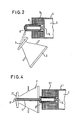
- FIG. 3 shows the inhalation device with a housing 15 which surrounds the exchangeable inhalation container 4, the atomizing element 1, the control electronics 2 and current sources in the form of batteries 16.
- the inhalation container 4 ' is arranged on the back of the atomizer element 1 and is equipped with a channel 17 which projects through the center of the atomizer element 1' and in the central area in front of the atomizer surface 7 'outlet nozzles 6' for the inhalation liquid 3 having.
- the inhalation which is expelled in portions, is brought very close through the nozzles 6 'to the atomizing surface 7' of the atomizing element 1, without the supply member 17 for the inhaling liquid being able to interfere with the atomizing area.
Abstract
Description
Vorliegende Erfindung bezieht sich auf eine Inhaliervorrichtung mit einer Dosiereinrichtung für Inhalate mit einem Inhalatbehälter sowie mit einer Pumpeinrichtung für die Zulieferung der Inhalatflüssigkeit zu einem Zerstäuberelement, insbesondere zum Einsatz in Inhalationsgeräten mit einem Ultraschallzerstäubungssystem.The present invention relates to an inhalation device with a metering device for inhalants with an inhalation container and with a pump device for supplying the inhalation liquid to an atomizer element, in particular for use in inhalation devices with an ultrasonic atomization system.
Bei bekannten Inhalationsgeräten, die z.B. mit einer medizinischen Wirkstoff-Flüssigkeit angefüllt sind und die zur Behandlung der Atemwege, beispielsweise bei Asthma-Erkrankten, dienen, erfolgt die Dosierung des flüssigen Wirkstoffes auf mechanischem Wege über einen auf dem Pumpenprinzip beruhenden Fördermechanismus, mittels welchem eine vorbestimmte Portion der Flüssigkeit zu einem Zerstäuberelement, z.B. zu einer Zerstäuberdüse gebracht werden kann (DE-PS 28 54 841). Insbesondere bei Inhalationsgeräten für Asthma-Kranke, deren Flüssigkeitsbehälter mehrere Inhalationsportionen enthalten, ist es von außerordentlicher Wichtigkeit, daß bei jedem Inhalationsvorgang dem Asthma-Kranken eine vorbestimmte, exakt dosierte Inhalatmenge zugeführt wird. Schon relativ geringe Abweichungen von dieser Sollmenge führen entweder zur völligen Wirkungslosigkeit des Wirkstoffes oder aber zu schwerwiegenden Schädigungen der Atemwege der behandelten Person. Bekannte Inhalationsgeräte der vorgenannten Art, die nach dem Kolben-Saugpumpen-Prinzip arbeiten, besitzen zur Erlangung einer exakten Dosierung der Inhalat-Portionen eine konstruktiv sehr aufwendige Bauweise, wobei zu befürchten ist, daß bei nicht exakter Einhaltung der sehr engen Konstruktionstoleranzen eine genaue gleichbleibende Dosierung des Inhalats nicht mehr gewährleistet ist.In known inhalation devices, which are filled, for example, with a medicinal active substance liquid and which are used to treat the respiratory tract, for example in those with asthma, the liquid active substance is metered mechanically via a conveying mechanism based on the pump principle, by means of which a predetermined mechanism is used Portion of the liquid can be brought to an atomizing element, for example to an atomizing nozzle (DE-PS 28 54 841). In particular in the case of inhalation devices for asthma sufferers, the liquid containers of which contain several inhalation portions, it is extremely important that a predetermined, precisely metered amount of inhalation is supplied to the asthma sufferer during each inhalation process. Even relatively small deviations from this target amount lead either to the complete ineffectiveness of the active ingredient or to serious damage to the respiratory tract of the person being treated. Known inhalation devices of the aforementioned type, which work according to the piston suction pump principle, have to achieve an exact dosage Inhaled portions are structurally very complex, with the fear that if the very narrow design tolerances are not exactly adhered to, an exact constant dosage of the inhalant will no longer be guaranteed.
Um diesem Mangel zu begegnen, ist eine Dosiereinrichtung für Inhalate bekannt geworden (DE-AS 29 34 732), bei der als Pumpeinrichtung eine mit der Inhalatflüssigkeit in Verbindung stehende Zahnradpumpe vorgesehen ist, deren mit dem Inhalatbehälter luftdicht verbundenes Pumpengehäuse einen zum Zerstäuberelement führenden Austrittskanal aufweist und die durch ein Betätigungsorgan entsprechend der gewünschten Dosierung betätigbar ist. Soll eine derartige Vorrichtung die Forderungen an eine erforderriche Dosiergenauigkeit des Inhalats erbringen, so ist deren Herstellungsaufwand erheblich. Der vorliegenden Erfindung liegt nunmehr die Aufgabe zugrunde, eine Dosiereinrichtung für Inhalate der eingangs genannten Art so auszugestalten, daß bei einfacher und raumsparender konstruktiver Ausgestaltung ein Höchstmaß an Sicherheit in Bezug auf die exakte Dosierung der Inhalats-Portionen gewährleistet ist. Es ist zu berücksichtigen, daß mechanische Vorstellungstoleranz-Ungenauigkeiten sich möglichst kaum auf die Inhalat-Portionierung auswirken und daß eine Möglichkeit zum Ausgleich dieser Toleranz-Ungenauigkeiten auf einfache Art und Weise gegeben ist. Insbesondere ist der Umstand zu berücksichtigen, daß die Flüssigkeitsmengen des Inhalats im Vorratsbehälter oder im Leitungssystem von schädlichen Einflüssen, wie z.B. Umgebungsluft oder Bakterien geschützt werden sollen.In order to counter this deficiency, a metering device for inhalants has become known (DE-AS 29 34 732), in which a gear pump connected to the inhalant liquid is provided as the pump device, the pump housing of which is connected to the inhalant container in an airtight manner and has an outlet channel leading to the atomizing element and which can be actuated by an actuator according to the desired dosage. If such a device is to meet the requirements for a required metering accuracy of the inhalant, its manufacturing outlay is considerable. The present invention is based on the object of designing a metering device for inhalants of the type mentioned at the outset in such a way that, with a simple and space-saving structural design, a maximum of safety is guaranteed with regard to the exact metering of the inhalant portions. It must be taken into account that mechanical imagination tolerance inaccuracies have as little effect as possible on the inhalation portioning and that there is a possibility for compensating for these tolerance inaccuracies in a simple manner. In particular, the fact must be taken into account that the liquid quantities of the inhalant in the storage container or in the piping system are affected by harmful influences, e.g. Ambient air or bacteria should be protected.
Eine Inhaliervorrichtung mit einer Dosiereinrichtung für Inhalate, die diesen Forderungen im vollen Umfang entspricht, ist erfindungsgemäß gekennzeichnet durch einen in die Inhaliervorrichtung einbringbaren, hermetisch geschlossenen Vorratsbehälter mit unter elastischem Druck stehendem Inhalat und mit einer durch ein zeitsteuerbares Ventil verschlossenen in Richtung auf das Zerstäuberelement ausgerichteten Düse sowie durch eine Zeitsteueranordnung für dieses Ventil.An inhalation device with a metering device for inhalants, which fully meets these requirements, is characterized according to the invention by a hermetically sealed storage container which can be introduced into the inhalation device and has an inhalant under elastic pressure and with a nozzle which is closed in the direction of the atomizer element and closed by a time-controllable valve, and by a time control arrangement for this valve.
Eine nach diesen erfindungsgemäßen Merkmalen ausgestattete Inhaliervorricht.ung mit einer Dosiereinrichtung für Inhalate zeichnet sich dadurch aus, daß für die Dosierung des Inhalats bei der Zuführung an das Zerstäuberelement neben dem auf das Inhalat wirkenden elastischen Druck die Austrittsdüse und die Zeitsteueranordnung ausschlaggebend ist. Düsen sind mit hoher Präzision einfach herstellbar. Der auf das Inhalat wirkende elastische Druck wird durch den Hersteller der Inhalatfüllungen mit der nötigen Genauigkeit vorgegeben. Durch die Verwendung einer auf das Ventil wirkenden Zeitsteueranordnung ist darüber hinaus die Möglichkeit für die Einstellbarkeit einer Inhalat-Dosiermenge gegeben, wobei Herstellungs-Toleranzen durch Veränderung des Zeitfaktors einfach korrigierbar sind. Dies ist insbesondere dann der Fall, wenn eine elektronische Zeitsteueranordnung vorgesehen ist. Bevorzugterweise wirkt diese auf ein im Bereich der Düse des Inhalationsbehälters angeordnetes elektromagnetisches Ventil.An inhaler device equipped according to the features of the present invention with a metering device for inhalants is characterized in that, in addition to the elastic pressure acting on the inhalant, the outlet nozzle and the timing arrangement are decisive for the metering of the inhalant when it is fed to the atomizer element. Nozzles are easy to manufacture with high precision. The elastic pressure acting on the inhalant is specified with the necessary accuracy by the manufacturer of the inhalant fillings. Through the use of a timing control arrangement acting on the valve, there is also the possibility for the adjustability of an inhaled dosage amount, wherein manufacturing tolerances can be easily corrected by changing the time factor. This is particularly the case when an electronic timing arrangement is provided. This preferably acts on an electromagnetic valve arranged in the region of the nozzle of the inhalation container.
Nach einer bevorzugten Weiterbildung ist die erfindungsgemäße Inhaliervorrichtung dadurch gekennzeichnet, daß die Zeitsteueranordnung für das Ventil zusätzlich der Aktivierung des Zerstäuberelements zugeordnet ist. Bei einer dermaßen ausgestalteten Inhaliervorrichtung wird durch eine einzige Betätigung eines Auslöseorgans an der Inhäliervorrichtung das dem Zerstäuberelement durch die Dosiervorrichtung zugeführte Inhalat sofort zerstäubt. Die Ansteuer-Vorrichtung ist sicherheitshalber zweckmäßig so ausgestaltet, daß eine wiederholte dosierte Zuführung von Inhalatflüssigkeit an das Zerstäuberelement erst dann wieder möglich ist, wenn der Betätigungsmechanismus der Inhaliervorrichtung vorher wieder freigegeben wurde.According to a preferred development, the inhalation device according to the invention is characterized in that the timing arrangement for the valve is additionally associated with the activation of the atomizer element. In the case of an inhalation device of this type, the inhalation supplied to the atomizer element by the metering device is atomized immediately by a single actuation of a triggering element on the inhalation device. For safety's sake, the control device is expediently designed such that repeated metered supply of inhalation liquid to the atomizing element is only possible again when the actuating mechanism of the inhalation device has been released again beforehand.
Nach einer bevorzugten Ausgestaltung ist die erfindungsgemäße Inhaliervorrichtung dadurch gekennzeichnet, daß das elektromagnetische Ventil gebildet ist durch einen im Inhalatbehälter angeordneten Magnetanker mit steuerbarer Schließventilfunktion und durch eine in der Inhaliereinrichtung angeordnete Elektromagnetspule für die Magnetanker. Nach einer anderen bevorzugten Ausgestaltung ist die erfindungsgemäße Inhaliervorrichtung dadurch gekennzeichnet, daß das elektromagnetische Ventil gebildet ist durch einelMagnetanker und eine elektrisch mit der Zeitsteuerung der Inhaliervorrichtung kontaktierbaren Elektromagnetspule im Inhalatbehälter. Ist die Elektromagnetspule Bestandteil der Inhaliereinrichtung, so kann die Zeitsteuerung unmittelbar für die elektromagnetische Charakteristik dieser Spule einjustiert sein.According to a preferred embodiment, the inhalation device according to the invention is characterized in that the electromagnetic valve is formed by a magnet armature arranged in the inhalation container with a controllable closing valve function and by an electromagnetic coil arranged in the inhalation device for the magnet armature. According to another preferred embodiment, the inhalation device according to the invention is characterized in that the electromagnetic valve is formed by a magnetic armature and an electromagnetic coil in the inhalation container that can be contacted electrically with the timing of the inhalation device. If the electromagnetic coil is part of the inhalation device, the time control can be adjusted directly for the electromagnetic characteristics of this coil.
Im Rahmen der Erfindung sind weitere bevorzugte Ausgestaltungen der Inhaliervorrichtung wahlweise realisierbar. So ist es beispielsweise möglich, im Inhalatbehälter einen durch das - oder federdruckbeaufschlagten - auf die Inhaltionsflüssigkeit wirkenden Kolben anzuordnen. Dieser Kolben, welcher auch durch eine Membrane ersetzt sein kann, dient zur möglichst vollkommenen Trennung des Inhalats von Umwelteinflüssen. Andererseits bietet es sich an, daß der Inhalatsbehälter mit seiner Düse durch das Zerstäuberelement hindurch in den Bereich des Zentrums, dessen Zerstäuberfläche geführt ist, insbesondere dann, wenn das Zerstäuberelement bevorzugterweise ein Biegeschwinger ist. Damit wird eine Zuführung des Inhalats an das Zerstäuberelement in unmittelbarer Nähe durchgeführt, ohne daß diese Zuführung die Zerstäubung des Inhalats nachteilig beeinflussen könnte.Within the scope of the invention, further preferred configurations of the inhalation device can optionally be implemented. For example, it is possible to arrange in the inhalation container a piston which acts on the inhalation liquid through the - or spring-pressurized. This piston, which can also be replaced by a membrane, serves to separate the inhalant from environmental influences as completely as possible. On the other hand, it makes sense for the inhalation container with its nozzle to pass through the atomizer element into the area of the center, the atomizer surface of which is guided, in particular when the atomizer element is preferably a flexural oscillator. In this way, the inhalant is supplied to the atomizer element in the immediate vicinity, without this supply being able to adversely affect the atomization of the inhalant.
Mit Merkmalen der Erfindung ausgestattete Ausführungsbeispiele sind anhand der Zeichnung im folgenden näher beschrieben.Exemplary embodiments equipped with features of the invention are described in more detail below with reference to the drawing.
Es zeigen:
- Fig. 1 eine schematische Darstellung der Inhaliervorrichtung mit einer Dosiereinrichtung,
- Fig. 2 eine Einzelheit im Bereich des Zerstäuberelementes und der diesem nahen Dosiervorrichtung,
- Fig. 3 eine schematische Darstellung der Anordnung der Bauteile in einem handlichen Inhalator und
- Fig. 4 eine weitere Zuordnung der Dosiereinrichtung zum Zerstäuberelement.
- 1 is a schematic representation of the inhalation device with a metering device,
- 2 shows a detail in the area of the atomizer element and the metering device close to it,
- Fig. 3 is a schematic representation of the arrangement of the components in a handy inhaler and
- Fig. 4 shows a further assignment of the metering device to the atomizer element.
Als Zerstäuberelement 1 ist im vorliegenden Ausführungsbeispiel ein Piezo-Biegeschwingersystem angeordnet, welches durch eine entsprechende, ebenfalls bekannte elektronische Schaltungsanordnung ansteuerbar ist. Die zu zerstäubende Inhalatflüssigkeit 3 ist von einem Inhalatbehälter 4 hermetisch geschützt gegen Umwelteinflüsse. Ein Federelement 5 übt über einen Kolben16 einen elastischen Druck auf die Inhalatsflüssigkeit 3 aus. Eine Düse 6 des Inhaltbehälters 4 ist in Richtung auf die Zerstäuberfläche 7 des Zerstäuberelements 1 ausgerichtet und durch ein Ventil 8 über eine Druckfeder 9 verschlossen. Dieses Ventil 8 beinhaltet zumindest einen Teilbereich 10 aus ferromagnetischem Material, welcher die Aufgabe eines Tauchankermagneten übernimmt. Zur Ansteuerung dieses Tauchankermagneten 10 dient eine elektromagnetische Spule 11.In the present exemplary embodiment, a piezo bending vibrator system is arranged as the atomizing element 1, which system can be controlled by a corresponding, likewise known electronic circuit arrangement. The
Bei Betätigung eines Tastschalters 12 wird innerhalb der elektronischen Schaltungsanordnung 2 eine Zeitsteueranordnung ausgelöst. In Abhängigkeit dieses Auslösekriteriums wird die elektromagnetische Spule 11 für eine vorgegebene Zeitspanne erregt, so daß über die Tauchankerfunktion das Ventil 8 die Düse 6 für diese Zeitspanne freigibt und die unter Druck stehende Inhalatflüssigkeit 3 in Richtung auf die Zerstäuberfläche 7 des Zerstäuberelements 1 portioniert gespritzt wird. Gleichzeitig wird über die elektronische Schaltungsanordnung 2 das Zerstäuberelement 1 erregt, so daß die auf die Zerstäuberfläche 7 gelangte Inhalatmenge atmungsgerecht zerstäubt wird.When a
Aus Fig. 2 ist eine Einzelheit im Bereich der Düse 6 des Inhalatbehälters 4 und des Zerstäuberelements ersichtlich. Die Düse 6 ist so ausgestaltet und angeordnet, daß die Zerstäuberfläche durch das auftreffende Inhalat möglichst gleichmäßig so benetzt wird, daß eine gute Zerstäubungswirkung erreicht wird. Um den bei geöffneter Düse 6 anstehenden Druck der Inhalatflüssigkeit vom anstehenden Druck im Inhalatbehälter 4 möglichst zu entkoppeln, d.h. um diesen dynamischen Druck möglichst konstant auszulegen, ist zwischen der Ventilkammer und dem eigentlichen Vorratsraum für die Inhalatflüssigkeit 3 innerhalb des Inhalatbehälters 4 eine Reduzierdüse 14 angeordnet.2 shows a detail in the area of the nozzle 6 of the inhalation container 4 and the atomizer element. The nozzle 6 is designed and arranged in such a way that the atomizing surface is wetted as evenly as possible by the incident inhalation so that a good atomizing effect is achieved. In order to decouple the pressure of the inhalation liquid from the pressure in the inhalation container 4 when the nozzle 6 is open, i.e. In order to design this dynamic pressure as constant as possible, a reducing
Die Fig. 3 zeigt die Inhaliervorrichtung mit einem Gehäuse 15, welches den auswechselbaren Inhalatbehälter 4, des Zerstäuberelements 1, die Ansteuerelektronik 2 und Stromquellen in Form von Batterien 16 umgibt.3 shows the inhalation device with a
Bei der Ausführungsform gemäß Fig. 4 ist der Inhalatsbehälter 4' auf der Rückseite des Zerstäuberelements 1 angeordnet und mit einem Kanal 17 ausgestattet, welcher durch das Zerstäuberelement 1' mittig hindurchragt und im mittigen Bereich vor der Zerstäuberfläche 7' Austrittsdüsen 6' für die Inhalatflüssigkeit 3 aufweist. Damit wird das portionsweise ausgestoßene Inhalat äußerst nahe durch die Düsen 6' an die Zerstäuberfläche 7' des Zerstäuberelements 1 herangebracht, ohne daß das Zuführungsorgan 17 für die Inhalatflüssigkeit den Zerstäubungsbereich störend beeinflussen könnte.In the embodiment according to FIG. 4, the inhalation container 4 'is arranged on the back of the atomizer element 1 and is equipped with a
Claims (10)
Priority Applications (1)
| Application Number | Priority Date | Filing Date | Title |
|---|---|---|---|
| AT83111134T ATE27918T1 (en) | 1982-12-03 | 1983-11-08 | INHALER WITH A DOSING DEVICE FOR INHALES. |
Applications Claiming Priority (2)
| Application Number | Priority Date | Filing Date | Title |
|---|---|---|---|
| DE3244836A DE3244836C2 (en) | 1982-12-03 | 1982-12-03 | Inhalation device with a metering device for inhalants |
| DE3244836 | 1982-12-03 |
Publications (3)
| Publication Number | Publication Date |
|---|---|
| EP0111163A2 true EP0111163A2 (en) | 1984-06-20 |
| EP0111163A3 EP0111163A3 (en) | 1984-12-12 |
| EP0111163B1 EP0111163B1 (en) | 1987-06-24 |
Family
ID=6179766
Family Applications (1)
| Application Number | Title | Priority Date | Filing Date |
|---|---|---|---|
| EP83111134A Expired EP0111163B1 (en) | 1982-12-03 | 1983-11-08 | Inhalation device with dosage means |
Country Status (3)
| Country | Link |
|---|---|
| EP (1) | EP0111163B1 (en) |
| AT (1) | ATE27918T1 (en) |
| DE (2) | DE3244836C2 (en) |
Cited By (16)
| Publication number | Priority date | Publication date | Assignee | Title |
|---|---|---|---|---|
| EP0156409A2 (en) * | 1984-02-23 | 1985-10-02 | Jean Michel Anthony | Device for moistening parts of the human body |
| GB2164569A (en) * | 1984-09-25 | 1986-03-26 | Etela Hameen Keuhkovammayhdist | Inhalation dispenser intended for accurate dispensing of predisposing drugs administered to persons with respiratory disease at the examination phase and/or of drugs to be administered in spray form in the course of therapy |
| EP0232235A2 (en) * | 1986-01-27 | 1987-08-12 | A/S GEA Farmaceutisk Fabrik | Medical dosing device for discharge of atomized medicament for inhalation air |
| WO1988009680A1 (en) * | 1987-06-06 | 1988-12-15 | Sandor Potak | Device for oral intake of a fluid medium |
| EP0569611A1 (en) * | 1992-05-13 | 1993-11-18 | Siemens Aktiengesellschaft | Spray device, particularly pocket spray device |
| FR2705911A1 (en) * | 1993-06-02 | 1994-12-09 | Oreal | Piezoelectric nebulization device. |
| EP1066850A1 (en) * | 1999-07-08 | 2001-01-10 | Siemens-Elema AB | Medical Nebulizer |
| GB2413498A (en) * | 2004-04-27 | 2005-11-02 | Bespak Plc | Dispensing apparatus having an electromagnetically operated valve |
| US7107986B2 (en) | 1997-06-10 | 2006-09-19 | Glaxo Group Limited | Dispenser with doses' counter |
| US7624968B2 (en) * | 2008-02-25 | 2009-12-01 | Hsueh-Yu Lu | Compressor nebulizer with a pressure gage |
| USD642330S1 (en) | 2009-10-26 | 2011-07-26 | Jeffrey Turner | Delivery device |
| CN103143088A (en) * | 2013-03-19 | 2013-06-12 | 卓效医疗有限公司 | Handheld type mini atomizer capable of facilitating change and charge of medicine |
| WO2013083530A2 (en) | 2011-12-05 | 2013-06-13 | Chiesi Farmaceutici S.P.A. | Method and system for electronic mdi model |
| US9050431B2 (en) | 2010-10-18 | 2015-06-09 | Jeffrey turner | Device for dispensing a medium |
| US9545489B2 (en) | 2010-10-18 | 2017-01-17 | Jeffrey Turner | Device for dispensing a medium |
| CN115645688A (en) * | 2022-11-09 | 2023-01-31 | 江苏童医医疗器械有限公司 | Atomizer capable of preventing bottle mouth from being polluted |
Families Citing this family (5)
| Publication number | Priority date | Publication date | Assignee | Title |
|---|---|---|---|---|
| DE3743043A1 (en) * | 1987-12-18 | 1989-07-13 | Anton Dinkel | Inhalation apparatus for treatment of the airways and other uses taking particular account of the hygiene of the inhaler, of the medicines, of the inhaled air, and of the controllable medicine vials/ampoules and of the atomiser |
| DE4300880C2 (en) * | 1993-01-15 | 1996-03-21 | Draegerwerk Ag | Ultrasonic nebulizer with dosing unit |
| US5970974A (en) * | 1995-03-14 | 1999-10-26 | Siemens Aktiengesellschaft | Dosating unit for an ultrasonic atomizer device |
| CA2215331C (en) * | 1995-03-14 | 2002-01-22 | Siemens Aktiengesellschaft | Ultrasonic atomizer device with removable precision dosating unit |
| DE19613185A1 (en) * | 1996-04-02 | 1997-10-09 | Pfeiffer Erich Gmbh & Co Kg | Dosing device for flowable media such as powder / air dispersions |
Citations (4)
| Publication number | Priority date | Publication date | Assignee | Title |
|---|---|---|---|---|
| DE2809255A1 (en) * | 1977-03-11 | 1978-09-14 | Rosenthal Richard R | DOSING SYSTEM FOR THE STIMULATION OF BRONCHIAL SPASMS |
| DE2724175B2 (en) * | 1977-05-27 | 1979-03-29 | Bosch-Siemens Hausgeraete Gmbh, 7000 Stuttgart | Inhaler for treating the respiratory tract |
| EP0004039A2 (en) * | 1978-03-15 | 1979-09-19 | Bosch-Siemens HausgerÀ¤te GmbH | Atomiser for liquids |
| FR2444504A1 (en) * | 1978-12-19 | 1980-07-18 | Bosch Siemens Hausgeraete | LIQUID ATOMIZER, PARTICULARLY INHALATION APPARATUS |
-
1982
- 1982-12-03 DE DE3244836A patent/DE3244836C2/en not_active Expired
-
1983
- 1983-11-08 AT AT83111134T patent/ATE27918T1/en not_active IP Right Cessation
- 1983-11-08 DE DE8383111134T patent/DE3372177D1/en not_active Expired
- 1983-11-08 EP EP83111134A patent/EP0111163B1/en not_active Expired
Patent Citations (4)
| Publication number | Priority date | Publication date | Assignee | Title |
|---|---|---|---|---|
| DE2809255A1 (en) * | 1977-03-11 | 1978-09-14 | Rosenthal Richard R | DOSING SYSTEM FOR THE STIMULATION OF BRONCHIAL SPASMS |
| DE2724175B2 (en) * | 1977-05-27 | 1979-03-29 | Bosch-Siemens Hausgeraete Gmbh, 7000 Stuttgart | Inhaler for treating the respiratory tract |
| EP0004039A2 (en) * | 1978-03-15 | 1979-09-19 | Bosch-Siemens HausgerÀ¤te GmbH | Atomiser for liquids |
| FR2444504A1 (en) * | 1978-12-19 | 1980-07-18 | Bosch Siemens Hausgeraete | LIQUID ATOMIZER, PARTICULARLY INHALATION APPARATUS |
Cited By (30)
| Publication number | Priority date | Publication date | Assignee | Title |
|---|---|---|---|---|
| EP0156409A2 (en) * | 1984-02-23 | 1985-10-02 | Jean Michel Anthony | Device for moistening parts of the human body |
| EP0156409A3 (en) * | 1984-02-23 | 1986-06-25 | Jean Michel Anthony | Device for moistening parts of the human body |
| GB2164569A (en) * | 1984-09-25 | 1986-03-26 | Etela Hameen Keuhkovammayhdist | Inhalation dispenser intended for accurate dispensing of predisposing drugs administered to persons with respiratory disease at the examination phase and/or of drugs to be administered in spray form in the course of therapy |
| EP0232235A2 (en) * | 1986-01-27 | 1987-08-12 | A/S GEA Farmaceutisk Fabrik | Medical dosing device for discharge of atomized medicament for inhalation air |
| EP0232235A3 (en) * | 1986-01-27 | 1989-05-03 | A/S GEA Farmaceutisk Fabrik | Medical dosing device for discharge of atomized medicament for inhalation air |
| WO1988009680A1 (en) * | 1987-06-06 | 1988-12-15 | Sandor Potak | Device for oral intake of a fluid medium |
| EP0569611A1 (en) * | 1992-05-13 | 1993-11-18 | Siemens Aktiengesellschaft | Spray device, particularly pocket spray device |
| EP0739654A2 (en) * | 1992-05-13 | 1996-10-30 | Siemens Aktiengesellschaft | Sprayer, in particular pocket sprayer |
| EP0739654A3 (en) * | 1992-05-13 | 1997-01-02 | Siemens Ag | Sprayer, in particular pocket sprayer |
| FR2705911A1 (en) * | 1993-06-02 | 1994-12-09 | Oreal | Piezoelectric nebulization device. |
| US5529055A (en) * | 1993-06-02 | 1996-06-25 | L'oreal | Piezoelectric nebulizing apparatus |
| US7107986B2 (en) | 1997-06-10 | 2006-09-19 | Glaxo Group Limited | Dispenser with doses' counter |
| US8245704B2 (en) | 1997-06-10 | 2012-08-21 | Glaxo Group Limited | Dispenser with doses' counter |
| EP1066850A1 (en) * | 1999-07-08 | 2001-01-10 | Siemens-Elema AB | Medical Nebulizer |
| WO2005105187A1 (en) * | 2004-04-27 | 2005-11-10 | Bespak Plc | Dispensing apparatus |
| GB2413498B (en) * | 2004-04-27 | 2008-06-25 | Bespak Plc | Dispensing apparatus |
| US7926482B2 (en) | 2004-04-27 | 2011-04-19 | Consort Medical Plc | Dispensing apparatus |
| GB2413498A (en) * | 2004-04-27 | 2005-11-02 | Bespak Plc | Dispensing apparatus having an electromagnetically operated valve |
| US7624968B2 (en) * | 2008-02-25 | 2009-12-01 | Hsueh-Yu Lu | Compressor nebulizer with a pressure gage |
| USD642330S1 (en) | 2009-10-26 | 2011-07-26 | Jeffrey Turner | Delivery device |
| US9545489B2 (en) | 2010-10-18 | 2017-01-17 | Jeffrey Turner | Device for dispensing a medium |
| US9050431B2 (en) | 2010-10-18 | 2015-06-09 | Jeffrey turner | Device for dispensing a medium |
| WO2013083530A2 (en) | 2011-12-05 | 2013-06-13 | Chiesi Farmaceutici S.P.A. | Method and system for electronic mdi model |
| WO2013083530A3 (en) * | 2011-12-05 | 2013-08-01 | Chiesi Farmaceutici S.P.A. | Method and system for electronic mdi model |
| CN104023774A (en) * | 2011-12-05 | 2014-09-03 | 凯西制药公司 | Method and system for electronic mdi model |
| RU2633269C2 (en) * | 2011-12-05 | 2017-10-11 | КЬЕЗИ ФАРМАЧЕУТИЧИ С.п.А. | Method and system for mdi electronic model (dosing inhalant device) |
| CN103143088A (en) * | 2013-03-19 | 2013-06-12 | 卓效医疗有限公司 | Handheld type mini atomizer capable of facilitating change and charge of medicine |
| CN103143088B (en) * | 2013-03-19 | 2015-05-27 | 卓效医疗有限公司 | Handheld type mini atomizer capable of facilitating change and charge of medicine |
| CN115645688A (en) * | 2022-11-09 | 2023-01-31 | 江苏童医医疗器械有限公司 | Atomizer capable of preventing bottle mouth from being polluted |
| CN115645688B (en) * | 2022-11-09 | 2023-10-20 | 江苏童医医疗器械有限公司 | Atomizer capable of preventing bottle mouth from being polluted |
Also Published As
| Publication number | Publication date |
|---|---|
| EP0111163B1 (en) | 1987-06-24 |
| EP0111163A3 (en) | 1984-12-12 |
| DE3372177D1 (en) | 1987-07-30 |
| ATE27918T1 (en) | 1987-07-15 |
| DE3244836A1 (en) | 1984-06-14 |
| DE3244836C2 (en) | 1984-09-27 |
Similar Documents
| Publication | Publication Date | Title |
|---|---|---|
| EP0111163B1 (en) | Inhalation device with dosage means | |
| DE2854841C2 (en) | Liquid atomizer, preferably inhalation device | |
| EP1304131B1 (en) | Inhalator | |
| DE69834210T2 (en) | Sprayer for an inhaler | |
| DE4300880C2 (en) | Ultrasonic nebulizer with dosing unit | |
| DE69935728T2 (en) | Aerosol generator and method of making an aerosol generator | |
| DE19535010C2 (en) | Use of a drop generator in a medical device for the metered delivery of a medicament to a fluid stream | |
| DE69720219T2 (en) | Nebulizer with metering device | |
| DE69725379T2 (en) | Dosing device for supplying additional gas or liquid in the breathing gas of an anesthetic or respirator | |
| DE10334591B4 (en) | Method for distributing liquid fragrances and apparatus for carrying out the method | |
| EP0258637A1 (en) | Ultrasonic pocket sprayer | |
| EP0569611B1 (en) | Spray device, particularly pocket spray device | |
| DE2651962C2 (en) | Device for infusing liquids | |
| DE4241073C1 (en) | Dispensing system for dosed discharge esp. of lubricant fluid - has container in which fluid is acted on by gas pressure produced in container and dosing pump connected to container | |
| EP0091994A1 (en) | Apparatus for generating gas under pressure | |
| DE1287260B (en) | Spray device | |
| DE1616190C3 (en) | Ventilator with mechanical volume limitation | |
| WO2019025052A1 (en) | Decontamination arrangement, system and decontamination method | |
| DE2837040A1 (en) | Inhaling fluid transport system - with conveyor band carrying soaked netting past atomiser plate | |
| WO1991006377A1 (en) | Spray head for spray device | |
| DE3508130C2 (en) | ||
| DE4438292A1 (en) | Dose-accurate aerosol generation for inhalation therapy | |
| DE2934732C2 (en) | Dosing device for inhalants | |
| EP3409300A1 (en) | Decontamination arrangement, system and decontamination method | |
| DE1955545B2 (en) | Fluid atomiser producing controlled size droplets - contains suction nozzle and pressure gas nozzle with coaxial outlet apertures |
Legal Events
| Date | Code | Title | Description |
|---|---|---|---|
| PUAI | Public reference made under article 153(3) epc to a published international application that has entered the european phase |
Free format text: ORIGINAL CODE: 0009012 |
|
| AK | Designated contracting states |
Designated state(s): AT CH DE FR GB LI NL SE |
|
| PUAL | Search report despatched |
Free format text: ORIGINAL CODE: 0009013 |
|
| AK | Designated contracting states |
Designated state(s): AT CH DE FR GB LI NL SE |
|
| 17P | Request for examination filed |
Effective date: 19850207 |
|
| RAP1 | Party data changed (applicant data changed or rights of an application transferred) |
Owner name: BOSCH-SIEMENS HAUSGERAETE GMBH |
|
| GRAA | (expected) grant |
Free format text: ORIGINAL CODE: 0009210 |
|
| AK | Designated contracting states |
Kind code of ref document: B1 Designated state(s): AT CH DE FR GB LI NL SE |
|
| REF | Corresponds to: |
Ref document number: 27918 Country of ref document: AT Date of ref document: 19870715 Kind code of ref document: T |
|
| REF | Corresponds to: |
Ref document number: 3372177 Country of ref document: DE Date of ref document: 19870730 |
|
| ET | Fr: translation filed | ||
| PLBE | No opposition filed within time limit |
Free format text: ORIGINAL CODE: 0009261 |
|
| STAA | Information on the status of an ep patent application or granted ep patent |
Free format text: STATUS: NO OPPOSITION FILED WITHIN TIME LIMIT |
|
| 26N | No opposition filed | ||
| PGFP | Annual fee paid to national office [announced via postgrant information from national office to epo] |
Ref country code: SE Payment date: 19891004 Year of fee payment: 7 |
|
| PGFP | Annual fee paid to national office [announced via postgrant information from national office to epo] |
Ref country code: AT Payment date: 19891018 Year of fee payment: 7 |
|
| PGFP | Annual fee paid to national office [announced via postgrant information from national office to epo] |
Ref country code: FR Payment date: 19891023 Year of fee payment: 7 |
|
| PGFP | Annual fee paid to national office [announced via postgrant information from national office to epo] |
Ref country code: GB Payment date: 19891031 Year of fee payment: 7 |
|
| PGFP | Annual fee paid to national office [announced via postgrant information from national office to epo] |
Ref country code: NL Payment date: 19891130 Year of fee payment: 7 |
|
| PGFP | Annual fee paid to national office [announced via postgrant information from national office to epo] |
Ref country code: CH Payment date: 19900129 Year of fee payment: 7 |
|
| PG25 | Lapsed in a contracting state [announced via postgrant information from national office to epo] |
Ref country code: DE Effective date: 19900801 |
|
| PG25 | Lapsed in a contracting state [announced via postgrant information from national office to epo] |
Ref country code: GB Effective date: 19901108 Ref country code: AT Effective date: 19901108 |
|
| PG25 | Lapsed in a contracting state [announced via postgrant information from national office to epo] |
Ref country code: SE Effective date: 19901109 |
|
| PG25 | Lapsed in a contracting state [announced via postgrant information from national office to epo] |
Ref country code: LI Effective date: 19901130 Ref country code: CH Effective date: 19901130 |
|
| PG25 | Lapsed in a contracting state [announced via postgrant information from national office to epo] |
Ref country code: NL Effective date: 19910601 |
|
| GBPC | Gb: european patent ceased through non-payment of renewal fee | ||
| NLV4 | Nl: lapsed or anulled due to non-payment of the annual fee | ||
| PG25 | Lapsed in a contracting state [announced via postgrant information from national office to epo] |
Ref country code: FR Effective date: 19910731 |
|
| REG | Reference to a national code |
Ref country code: CH Ref legal event code: PL |
|
| REG | Reference to a national code |
Ref country code: FR Ref legal event code: ST |
|
| EUG | Se: european patent has lapsed |
Ref document number: 83111134.9 Effective date: 19910705 |