EP0111019A1 - Hold-open mechanism for refrigerated display cabinet - Google Patents
Hold-open mechanism for refrigerated display cabinet Download PDFInfo
- Publication number
- EP0111019A1 EP0111019A1 EP82111346A EP82111346A EP0111019A1 EP 0111019 A1 EP0111019 A1 EP 0111019A1 EP 82111346 A EP82111346 A EP 82111346A EP 82111346 A EP82111346 A EP 82111346A EP 0111019 A1 EP0111019 A1 EP 0111019A1
- Authority
- EP
- European Patent Office
- Prior art keywords
- door
- hold
- spring
- open
- plate
- Prior art date
- Legal status (The legal status is an assumption and is not a legal conclusion. Google has not performed a legal analysis and makes no representation as to the accuracy of the status listed.)
- Granted
Links
- 230000007246 mechanism Effects 0.000 title claims abstract description 62
- 230000009471 action Effects 0.000 description 9
- 239000011521 glass Substances 0.000 description 7
- 230000004048 modification Effects 0.000 description 7
- 238000012986 modification Methods 0.000 description 7
- 230000000712 assembly Effects 0.000 description 5
- 238000000429 assembly Methods 0.000 description 5
- 238000007789 sealing Methods 0.000 description 3
- 238000010276 construction Methods 0.000 description 2
- 235000013611 frozen food Nutrition 0.000 description 2
- 238000009434 installation Methods 0.000 description 2
- 239000012858 resilient material Substances 0.000 description 2
- 229910000639 Spring steel Inorganic materials 0.000 description 1
- 230000000694 effects Effects 0.000 description 1
- 230000006872 improvement Effects 0.000 description 1
- 238000012423 maintenance Methods 0.000 description 1
- 239000000463 material Substances 0.000 description 1
- 239000002184 metal Substances 0.000 description 1
- 238000005057 refrigeration Methods 0.000 description 1
- 230000000717 retained effect Effects 0.000 description 1
- 230000003245 working effect Effects 0.000 description 1
Images


Classifications
-
- F—MECHANICAL ENGINEERING; LIGHTING; HEATING; WEAPONS; BLASTING
- F25—REFRIGERATION OR COOLING; COMBINED HEATING AND REFRIGERATION SYSTEMS; HEAT PUMP SYSTEMS; MANUFACTURE OR STORAGE OF ICE; LIQUEFACTION SOLIDIFICATION OF GASES
- F25D—REFRIGERATORS; COLD ROOMS; ICE-BOXES; COOLING OR FREEZING APPARATUS NOT OTHERWISE PROVIDED FOR
- F25D23/00—General constructional features
- F25D23/02—Doors; Covers
- F25D23/028—Details
-
- E—FIXED CONSTRUCTIONS
- E05—LOCKS; KEYS; WINDOW OR DOOR FITTINGS; SAFES
- E05D—HINGES OR SUSPENSION DEVICES FOR DOORS, WINDOWS OR WINGS
- E05D11/00—Additional features or accessories of hinges
- E05D11/10—Devices for preventing movement between relatively-movable hinge parts
- E05D11/1028—Devices for preventing movement between relatively-movable hinge parts for maintaining the hinge in two or more positions, e.g. intermediate or fully open
- E05D11/105—Devices for preventing movement between relatively-movable hinge parts for maintaining the hinge in two or more positions, e.g. intermediate or fully open the maintaining means acting perpendicularly to the pivot axis
-
- E—FIXED CONSTRUCTIONS
- E05—LOCKS; KEYS; WINDOW OR DOOR FITTINGS; SAFES
- E05D—HINGES OR SUSPENSION DEVICES FOR DOORS, WINDOWS OR WINGS
- E05D7/00—Hinges or pivots of special construction
- E05D7/08—Hinges or pivots of special construction for use in suspensions comprising two spigots placed at opposite edges of the wing, especially at the top and the bottom, e.g. trunnions
- E05D7/081—Hinges or pivots of special construction for use in suspensions comprising two spigots placed at opposite edges of the wing, especially at the top and the bottom, e.g. trunnions the pivot axis of the wing being situated near one edge of the wing, especially at the top and bottom, e.g. trunnions
-
- E—FIXED CONSTRUCTIONS
- E05—LOCKS; KEYS; WINDOW OR DOOR FITTINGS; SAFES
- E05Y—INDEXING SCHEME ASSOCIATED WITH SUBCLASSES E05D AND E05F, RELATING TO CONSTRUCTION ELEMENTS, ELECTRIC CONTROL, POWER SUPPLY, POWER SIGNAL OR TRANSMISSION, USER INTERFACES, MOUNTING OR COUPLING, DETAILS, ACCESSORIES, AUXILIARY OPERATIONS NOT OTHERWISE PROVIDED FOR, APPLICATION THEREOF
- E05Y2900/00—Application of doors, windows, wings or fittings thereof
- E05Y2900/20—Application of doors, windows, wings or fittings thereof for furniture, e.g. cabinets
- E05Y2900/202—Application of doors, windows, wings or fittings thereof for furniture, e.g. cabinets for display cabinets, e.g. for refrigerated cabinets
-
- F—MECHANICAL ENGINEERING; LIGHTING; HEATING; WEAPONS; BLASTING
- F25—REFRIGERATION OR COOLING; COMBINED HEATING AND REFRIGERATION SYSTEMS; HEAT PUMP SYSTEMS; MANUFACTURE OR STORAGE OF ICE; LIQUEFACTION SOLIDIFICATION OF GASES
- F25D—REFRIGERATORS; COLD ROOMS; ICE-BOXES; COOLING OR FREEZING APPARATUS NOT OTHERWISE PROVIDED FOR
- F25D2323/00—General constructional features not provided for in other groups of this subclass
- F25D2323/02—Details of doors or covers not otherwise covered
- F25D2323/024—Door hinges
Definitions
- the present invention relates generally to commercial refrigerator door assemblies and more particularly to a releasable hold-open mechanism for maintaining the door in an open position.
- Refrigerated display cabinets are widely used for retail sale of refrigerated and frozen food goods.
- a typical door construction includes a hingedly mounted door having a plurality of spaced, insulating glass panels.
- U.S. Patent Nos. 2,987,782 and 3,131,421, to Kurowski illustrate typical constructions for insulated door structures of this description.
- door arrangements as described above are typically provided with a spring-loading arrangement so that each door of the display cabinet is self-closing.
- a door of the display cabinet there are certain times when it is desired for a door of the display cabinet to be maintained in an open position, such as during stocking of the cabinet or maintenance.
- one desirable feature for the door assemblies of the display cabinet is a so-called hold-open mechanism so that the door may be selectively maintained in an open position.
- One typical type of hold-open mechanism for display cabinet door assemblies includes a plate or other abutment member movably mounted on the door frame of the display cabinet.
- the hold-open plate is adapted to engage. a portion of the hinged door when the door is in an open position and after the plate is suitably manipulated, thus acting to maintain the door in an open position. The door may then be closed again only by first manipulating the plate so that it is moved out of engagement with the door.
- hold-open mechanisms of this description relate to their non-yielding, positive engagement of the hinged door.
- the hold-open plate when the hold-open plate is in the hold-open position and positively engages the door, attempts to close the door or otherwise move it from the open position may cause damage to both the door, the hold-open mechanism and/or the door frame.
- damage to the door may include breakage of any glass panel and/or distortion of the door sufficient to require replacement.
- occurrences of this nature are extremely undesirable.
- a hold-open mechanism for a springloaded swinging door of a refrigerator display cabinet which may be easily used so as to maintain the door in an open position, yet which is releasable, i.e., may be overridden without causing damage, when the door is moved from the open position would be a desirable and practical improvement for refrigerated display cabinets having hingedly mounted door structures.
- a door hold-open mechanism for a door of a refrigerated display cabinet hingedly mounted to. a door frame for swinging movement between closed and open positions.
- the door is typically provided with spring means for urging the door toward the closed position as is well known, so that the door is self-closing and is urged into sealing engagement with the door frame.
- the hold-open mechanism of the present invention includes a stop plate affixed to the door and movable therewith.
- the stop plate includes a lobe portion, and is adapted to cooperate with a stop carried by a door hinge plate mounted on the door frame so that opening movement of the door is limited (usually to approximately 90 degrees).
- the hold-open mechanism further includes a hold-open spring mounted on the door frame and engageable with the lobe portion of the stop plate.
- the hold-open spring is mounted on the stop pin carried by one of the hinge plates mounted to the door frame.
- the hold-open spring has a generally hook-shaped configuration, and in the preferred embodiment it is pivotally mounted on the stop pin of the hinge plate.
- the free end portion of the spring is offset, and this end portion is adapted to engage and cooperate with the lobe portion of the stop plate so as to releasably retain the stop plate (and thus the door) when the door is in the open position.
- the nature of the pivotal mounting of the hold-open spring to the stop pin of the hinge plate permits the spring to be manually moved from a first inactive to a second hold-open position.
- the spring In the first position the spring does not reactively engage and retain the plate carried by the door, thus permitting the door to operate in a normal fashion.
- the spring In the second position, the spring is adapted to releasably engage and retain the plate so that the door is maintained in the open position, yet functions in a self-releasing fashion to automatically disengage when the door is moved from the open position with sufficient force.
- the hold-open spring is mounted on the stop pin of the hinge plate, and is pinned thereto.
- movement of the door of the display cabinet to its fully open position automatically moves the stop plate carried by the door into engagement with the hold-open spring so that the stop plate is releasably retained thereby and the door is maintained in its open position. Movement of the door from the open position with sufficient force disengages the stop plate from the hold-open spring so that the door again may swing in a normal fashion.
- the hold-open mechanism of the present invention may be easily fabricated and adapted to hinged door assemblies having a variety of configurations.
- FIG. 1 there is illustrated a refrigerated display cabinet 10 such as the type found in supermarkets and the like for storage and display of refrigerated and frozen food items. While the hold-open mechanism of the present invention has been found to be particularly suited for use on display cabinets of this type, it will be appreciated that the invention is equally suited to a wide variety of applications.
- the display cabinet 10 typically includes a generally rectangular metal frame 12 including spaced upper and lower door frame members 14, and a plurality of laterally spaced, vertically extending frame columns or mullions 18.
- Door frame 12 supports one or more insulated glass doors 20 in side-by-side arrangement, each door 20 including a generally rectangular glass door frame 22 which supports a plurality of spaced, insulating glass panels 24.
- each glass door 20 is hingedly mounted for swinging movement with respect to door frame 12 by upper and lower hinge assemblies.
- the upper hinge assembly includes an upper hinge plate 26 which is adapted to be connected to a web portion 28 of upper frame member 14 by a mechanical fastener 30.
- An upper hinge pin 32 projecting upwardly of glass door frame 22 is adapted to fit within corresponding cut-out portions 27 and 29 in hinge plate 26 and web portion 28 for support of door 20.
- a hinge pin lock 34 is adapted to fit about upper hinge pin 32 for maintaining door 20 in position as is well known.
- Door 20 is further supported on door frame 12 by a lower hinge assembly which includes a lower hinge plate 36.
- Lower hinge plate 36 is adapted to be mounted on a web portion 38 of lower frame member 16 by a mechanical fastener 40.
- a lower hinge pin 42 extending downwardly from the door frame 22 is adapted to fit within one of cut-outs 44 defined by lower hinge plate 36.
- door 20 Installation of door 20 to door frame 12 is accomplished by respectively mounting upper and lower hinge plates 26 and 36 to upper and lower frame members 14 and 16.
- the upper and lower hinge plates shown in the drawing are of the type which may be shifted or adjusted with respect to the frame member upon which they are mounted so that the swinging axis of door 20 may be adjusted for proper alignment, although other door mounting arrangements may be used.
- door 20 may be lifted into door frame 12 such that upper hinge pin 32 fits into cut-outs 27 and 29 respectively defined by upper hinge plate 26 and web portion 28 of upper frame member 14.
- lower hinge pin 42 is raised sufficiently to clear lower hinge plate 36, and door 20 may be swung inwardly of the door frame 12.
- Hinge pin lock 34 may now be fitted about upper hinge pin 32 so that inadvertent lifting of the door out of the frame is prevented.
- door 20 incorporates a self-closing mechanism so that it is urged toward a closed position with respect to the door frame 12, and is urged into sealing engagement with the frame.
- a self-closing mechanism are well known.
- a self-closing action is typically provided by a spring-loading mechanism associated with one or both of upper and lower hinge pins 32 and 42.
- stop plate 46 is provided on door 20. As shown, stop plate 46 includes a cut-out 47 so that it fits about lower hinge pin 42, and is suitably affixed to door 20 by a mechanical fastener 48. The exact configuration and function of stop plate 46 will be further described.
- the hold-open mechanism of the present invention further includes a hold-open spring 50 movably mounted on a spring pin 52 projecting upwardly from lower hinge plate 36.
- Hold-open spring 50 is maintained in position on spring pin 52 by a spring guard 54 mounted on hinge plate 36 by mechanical fastener 58.
- Spring guard 54 includes an outwardly projecting finger portion 56 which is disposed generally adjacent to and above hold-open spring 50.
- hold-open spring 50 which may be suitably fabricated from heat treated spring steel or other suitably resilient material, has a generally hook-shaped configuration and includes several distinct portions. Specifically, spring 50 includes a mounting end portion 60 which is shaped so that it fits about spring pin 52. Spring 50 further includes a first leg 62, which includes an offset abutment portion 64, and a second leg 66 disposed at an angle to the first leg 62. The second leg 66 terminates in an offset free end portion 68 having a generally S-shaped configuration.
- spring 50 is preferably fabricated from a single piece of material, it will be appreciated that a similar member could be provided having the requisite resiliency such as by joining substantially rigid leg portions by a resilient interconnection.
- stop plate 46 affixed to door 20 includes a lobe portion 70 at one end thereof spaced from the swinging axis of the door.
- the lobe portion 70 defines a pair of shoulders 72 and 74 on opposite sides thereof.
- a cut-out portion 76 defined by the plate accommodates movement of the door without interference of the plate with other portions of the mechanism.
- Swinging movement of door 20 from the position illustrated in Figure 3 causes rotation of stop plate 46 therewith.
- shoulder 74 of the stop plate moves toward spring pin 52 on hinge plate 36.
- shoulder 74 engages and abuts spring pin 52.
- shoulder 74 actually abuts end portion 60 of hold-open spring 50 mounted on spring pin 52.
- This cooperative interengagement of the stop plate 46 with the spring pin 52 prevents further opening movement of the door 20.
- the position of hold-open spring 50 shown in Figure 3 is such that lobe portion 70 of the stop plate may clear the spring 50 without reactive engagement therewith, thus permitting the door to swing in a normal fashion.
- hold-open mechanism of the present invention provides this action in a simple and straightforward fashion.
- Stock personnel would first move door 20 toward its fully open position, as illustrated in Figures 4 and 5.
- hold-open spring 50 may be easily manipulated so that it is moved from the position shown in Figure 3 to the right, as shown by the phantom arrow in Figure 4.
- the free end portion 68 of hold-open spring 50 is urged over lobe portion 70 of stop plate 46 such that free end portion 68 engages shoulder 72 of the stop plate 46.
- Figure 5 illustrates hold-open spring 50 after having been so moved with respect to spring pin 52 such that free end portion 68 of the spring is in engagement with shoulder 72 of the stop plate 46.
- hold-open spring In this position of the hold-open spring, its reactive engagement with stop plate 46 releasably retains the stop plate so that door 20 is releasably maintained in its open position. With the door 20 maintained in its opened position, stock personnel may easily stock the shelves of refrigerator display cabinet 10.
- the hold-open mechanism of the present invention provides for essentially automatic disengagement of stop plate 46 from hold-open spring 50 so that door 20 is again biased toward its closed position by the self-closing mechanism.
- exertion of sufficient force on door 20, such as by manually pushing the door results in stop plate 46 disengaging from hold-open spring 50.
- This action is accomodated by reactive engagement and abutment of the portion of lobe portion 70 which defines shoulder 74 with offset abutment portion 64 of spring 50. This engagement displaces the spring such that free end portion 68 is urged out of engagement with shoulder portion 72.
- the hold-open mechanism is provided in an extremely simple fashion.
- the self-releasing nature of the releasable engagement of stop plate 46 with hold-open spring 50 assures that inadvertent closing movement of door 20 while the hold-open mechanism is engaged will not result in damage to the mechanism or the door.
- the hold-open mechanism is designed to resist closing torque on the door on the order of 100 foot-pounds before disengagement of spring 50 and plate 46.
- biasing spring 77 is disposed in a captive fashion between spring guard 54 and hold-open spring 50. In this way, spring 50 is biased and urged from its first inactive position toward its second active position for reactive engagement with stop plate 46.
- Biasing spring 77 may comprise any suitable resilient material, with a small piece of elastomeric surgical tubing having proved durable and effective.
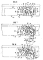
- FIG. 6-8 a further modified version of the hold-open mechanism of the present invention is shown.
- the arrangement shown in these figures is substantially the same as the hold-open mechanism illustrated in Figures 3-5.
- hold-open spring 50 of the mechanism is shown fixedly attached to spring pin 52 of lower hinge plate 36 by a pin 78 or other suitable mechanical fastener means.
- pin 78 prevents movement of spring 52 between a first inactive position and a second engaging, hold-open position, as previously described.
- This modification provides a slightly different working action for the hold-open mechanism.
- door 20 (shown in phantom) is in its closed position.
- lobe portion 70 of stop plate 46 is moved toward free end portion 68 of hold-open spring 50.
- the configuration of end portion 68 causes it to engage and cam against lobe portion 70 of plate 46 so that the spring "rides up” lobe portion 70.
- Self-releasing disengagement of the hold-open mechanism of this embodiment is provided as described above. Exertion of sufficient force on door 20 results in free end portion 68 of hold-open spring 50 slipping off of and disengaging from shoulder 72 of stop plate 46. After stop plate 46 is disengaged from the hold-open spring 50, the self-closing action of door 20 again moves the door toward its closed position as the door swings closed in a normal fashion.
- a novel and simple hold-open mechanism is disclosed for hingedly mounted door arrangements which is particularly suited for use with self-closing doors of refrigerated display cabinets.
- the hold-open mechanism incorporating the present invention operates to permit closing of the door by overriding or self-release, thus preventing damange to the door or door frame even when the hold-open mechanism is engaged.
- the releasable hold-open mechanism may be configured for manual or automatic engagement or operation without detracting from its releasing characteristics.
Landscapes
- Engineering & Computer Science (AREA)
- Mechanical Engineering (AREA)
- Chemical & Material Sciences (AREA)
- Combustion & Propulsion (AREA)
- Physics & Mathematics (AREA)
- Thermal Sciences (AREA)
- General Engineering & Computer Science (AREA)
- Refrigerator Housings (AREA)
Abstract
Description
- The present invention relates generally to commercial refrigerator door assemblies and more particularly to a releasable hold-open mechanism for maintaining the door in an open position.
- Refrigerated display cabinets are widely used for retail sale of refrigerated and frozen food goods. A typical door construction includes a hingedly mounted door having a plurality of spaced, insulating glass panels. U.S. Patent Nos. 2,987,782 and 3,131,421, to Kurowski illustrate typical constructions for insulated door structures of this description.
- In order to minimize the load on the refrigeration unit of the refrigerated display cabinet, and to effect sealing of the door with the door frame of the display case, door arrangements as described above are typically provided with a spring-loading arrangement so that each door of the display cabinet is self-closing. However, there are certain times when it is desired for a door of the display cabinet to be maintained in an open position, such as during stocking of the cabinet or maintenance. Thus, one desirable feature for the door assemblies of the display cabinet is a so-called hold-open mechanism so that the door may be selectively maintained in an open position.
- One typical type of hold-open mechanism for display cabinet door assemblies includes a plate or other abutment member movably mounted on the door frame of the display cabinet. The hold-open plate is adapted to engage. a portion of the hinged door when the door is in an open position and after the plate is suitably manipulated, thus acting to maintain the door in an open position. The door may then be closed again only by first manipulating the plate so that it is moved out of engagement with the door.
- One problem with hold-open mechanisms of this description relates to their non-yielding, positive engagement of the hinged door. Specifically, when the hold-open plate is in the hold-open position and positively engages the door, attempts to close the door or otherwise move it from the open position may cause damage to both the door, the hold-open mechanism and/or the door frame. For example, damage to the door may include breakage of any glass panel and/or distortion of the door sufficient to require replacement. Naturally, occurrences of this nature are extremely undesirable.
- Thus, a hold-open mechanism for a springloaded swinging door of a refrigerator display cabinet which may be easily used so as to maintain the door in an open position, yet which is releasable, i.e., may be overridden without causing damage, when the door is moved from the open position would be a desirable and practical improvement for refrigerated display cabinets having hingedly mounted door structures.
- In accordance with the present invention, a door hold-open mechanism is provided for a door of a refrigerated display cabinet hingedly mounted to. a door frame for swinging movement between closed and open positions. The door is typically provided with spring means for urging the door toward the closed position as is well known, so that the door is self-closing and is urged into sealing engagement with the door frame.
- The hold-open mechanism of the present invention includes a stop plate affixed to the door and movable therewith. The stop plate includes a lobe portion, and is adapted to cooperate with a stop carried by a door hinge plate mounted on the door frame so that opening movement of the door is limited (usually to approximately 90 degrees).
- The hold-open mechanism further includes a hold-open spring mounted on the door frame and engageable with the lobe portion of the stop plate. In the preferred embodiment, the hold-open spring is mounted on the stop pin carried by one of the hinge plates mounted to the door frame.
- The hold-open spring has a generally hook-shaped configuration, and in the preferred embodiment it is pivotally mounted on the stop pin of the hinge plate. The free end portion of the spring is offset, and this end portion is adapted to engage and cooperate with the lobe portion of the stop plate so as to releasably retain the stop plate (and thus the door) when the door is in the open position.
- The nature of the pivotal mounting of the hold-open spring to the stop pin of the hinge plate permits the spring to be manually moved from a first inactive to a second hold-open position. In the first position the spring does not reactively engage and retain the plate carried by the door, thus permitting the door to operate in a normal fashion. In the second position, the spring is adapted to releasably engage and retain the plate so that the door is maintained in the open position, yet functions in a self-releasing fashion to automatically disengage when the door is moved from the open position with sufficient force.
- In a modification of the preferred embodiment, the hold-open spring is mounted on the stop pin of the hinge plate, and is pinned thereto. In this embodiment, movement of the door of the display cabinet to its fully open position automatically moves the stop plate carried by the door into engagement with the hold-open spring so that the stop plate is releasably retained thereby and the door is maintained in its open position. Movement of the door from the open position with sufficient force disengages the stop plate from the hold-open spring so that the door again may swing in a normal fashion.
- As will be appreciated from the following detailed description, the hold-open mechanism of the present invention may be easily fabricated and adapted to hinged door assemblies having a variety of configurations.
- Numerous other advantages and features of the present invention will become readily apparent from the following detailed description of the invention and embodiment thereof, from the claims and from the accompanying drawingx in which like numerals are employed to designate like parts throughout the same.
-
- FIGURE 1 is a partial perspective view of a refrigerated display cabinet;
- FIGURE 2 is an exploded perspective view of the door mounting arrangement of the display cabinet of Figure 1 including the hold-open mechanism of the present invention;
- FIGURES 3-5 illustrate the hold-open mechanism of Figure 2 during swinging movement of the door of the display cabinet illustrated in Figure 1;
- FIGURE 5a illustrates a modification of the hold-open mechanism of Figures 2;
- FIGURES 6-8 are plan views of an alternate embodiment of the hold-open mechanism of the present invention during swinging movement of the door of the display cabinet of Figure 1.
- While the present invention is susceptible to embodiment in different forms, there is shown in the drawings and will hereinafter be described a preferred embodiment and alternate embodiments thereof with the understanding that the present disclosure is to be considered as an exemplification of the principles of the present invention and is not intended to limit the invention to the embodiments illustrated.
- With reference now to Figure 1, there is illustrated a refrigerated
display cabinet 10 such as the type found in supermarkets and the like for storage and display of refrigerated and frozen food items. While the hold-open mechanism of the present invention has been found to be particularly suited for use on display cabinets of this type, it will be appreciated that the invention is equally suited to a wide variety of applications. - The
display cabinet 10 typically includes a generallyrectangular metal frame 12 including spaced upper and lowerdoor frame members 14, and a plurality of laterally spaced, vertically extending frame columns ormullions 18.Door frame 12 supports one or moreinsulated glass doors 20 in side-by-side arrangement, eachdoor 20 including a generally rectangularglass door frame 22 which supports a plurality of spaced,insulating glass panels 24. - As best shown in Figure 2, each
glass door 20 is hingedly mounted for swinging movement with respect todoor frame 12 by upper and lower hinge assemblies. The upper hinge assembly includes anupper hinge plate 26 which is adapted to be connected to aweb portion 28 ofupper frame member 14 by amechanical fastener 30. Anupper hinge pin 32 projecting upwardly ofglass door frame 22 is adapted to fit within corresponding cut-outportions hinge plate 26 andweb portion 28 for support ofdoor 20. A hinge pin lock 34 is adapted to fit aboutupper hinge pin 32 for maintainingdoor 20 in position as is well known. -
Door 20 is further supported ondoor frame 12 by a lower hinge assembly which includes alower hinge plate 36.Lower hinge plate 36 is adapted to be mounted on aweb portion 38 oflower frame member 16 by amechanical fastener 40. Alower hinge pin 42 extending downwardly from thedoor frame 22 is adapted to fit within one of cut-outs 44 defined bylower hinge plate 36. - Installation of
door 20 todoor frame 12 is accomplished by respectively mounting upper andlower hinge plates lower frame members door 20 may be adjusted for proper alignment, although other door mounting arrangements may be used. After the hinge plates are in place,door 20 may be lifted intodoor frame 12 such thatupper hinge pin 32 fits into cut-outs upper hinge plate 26 andweb portion 28 ofupper frame member 14. As thedoor 20 is lifted into the frame,lower hinge pin 42 is raised sufficiently to clearlower hinge plate 36, anddoor 20 may be swung inwardly of thedoor frame 12. Afterdoor 20 is swung inwardly, theentire door 20 may be lowered so thatlower hinge pin 42 fits within one of the cut-outs 44 defined bylower hinge plate 36, anddoor 22 is now supported withindoor frame 12. Hinge pin lock 34 may now be fitted aboutupper hinge pin 32 so that inadvertent lifting of the door out of the frame is prevented. - As noted,
door 20 incorporates a self-closing mechanism so that it is urged toward a closed position with respect to thedoor frame 12, and is urged into sealing engagement with the frame. Such self-closing mechanisms are well known. For example, a self-closing action is typically provided by a spring-loading mechanism associated with one or both of upper andlower hinge pins - In accordance with the present invention, a
stop plate 46 is provided ondoor 20. As shown, stopplate 46 includes a cut-out 47 so that it fits aboutlower hinge pin 42, and is suitably affixed to door 20 by amechanical fastener 48. The exact configuration and function ofstop plate 46 will be further described. - The hold-open mechanism of the present invention further includes a hold-
open spring 50 movably mounted on aspring pin 52 projecting upwardly fromlower hinge plate 36. Hold-open spring 50 is maintained in position onspring pin 52 by aspring guard 54 mounted onhinge plate 36 bymechanical fastener 58.Spring guard 54 includes an outwardly projectingfinger portion 56 which is disposed generally adjacent to and above hold-open spring 50. - With reference now to Figures 3-5, the exact configuration of the components of the hold-open mechanism of the present invention will be described. As shown, hold-
open spring 50, which may be suitably fabricated from heat treated spring steel or other suitably resilient material, has a generally hook-shaped configuration and includes several distinct portions. Specifically,spring 50 includes a mountingend portion 60 which is shaped so that it fits aboutspring pin 52.Spring 50 further includes afirst leg 62, which includes an offsetabutment portion 64, and asecond leg 66 disposed at an angle to thefirst leg 62. Thesecond leg 66 terminates in an offsetfree end portion 68 having a generally S-shaped configuration. - While
spring 50 is preferably fabricated from a single piece of material, it will be appreciated that a similar member could be provided having the requisite resiliency such as by joining substantially rigid leg portions by a resilient interconnection. - With further reference to Figures 3-5, stop
plate 46 affixed todoor 20 includes alobe portion 70 at one end thereof spaced from the swinging axis of the door. Thelobe portion 70 defines a pair ofshoulders portion 76 defined by the plate accommodates movement of the door without interference of the plate with other portions of the mechanism. - Normal swinging movement of
door 20 is provided withspring 50 in the position illustrated in Figure 3. As shown, door 20 (shown in phantom) is in its fully closed position. Cut-out portion 76 ofstop plate 46 is defined such that the stop plate clearsspring pin 52 onlower hinge plate 36 so that the spring pin is disposed within the cut-out portion. Hold-open spring 50 is illustrated in a first inactive position for normal swinging movement of thedoor 20 without hold-open action. - Swinging movement of
door 20 from the position illustrated in Figure 3 causes rotation ofstop plate 46 therewith. As the door is moved toward its fully opened position,shoulder 74 of the stop plate moves towardspring pin 52 onhinge plate 36. As the door is moved to its fully open position,shoulder 74 engages and abutsspring pin 52. (As shown,shoulder 74 actually abutsend portion 60 of hold-open spring 50 mounted on spring pin 52). This cooperative interengagement of thestop plate 46 with thespring pin 52 prevents further opening movement of thedoor 20. Notably, the position of hold-open spring 50 shown in Figure 3 is such thatlobe portion 70 of the stop plate may clear thespring 50 without reactive engagement therewith, thus permitting the door to swing in a normal fashion. - When the open door is released, movement of the
door 20 from the fully opened position is provided by the spring-loading mechanism associated therewith as is known. The lack of reactive engagement betweenstop plate 46 and hold-open spring 50 permits thedoor 20 to close in a normal fashion. - When it is desired that
door 20 be maintained in an open position, such as during stocking of the shelves of therefrigerated display cabinet 10, the hold-open mechanism of the present invention provides this action in a simple and straightforward fashion. Stock personnel would first movedoor 20 toward its fully open position, as illustrated in Figures 4 and 5. When thedoor 20 is in this position, hold-open spring 50 may be easily manipulated so that it is moved from the position shown in Figure 3 to the right, as shown by the phantom arrow in Figure 4. As this is done, thefree end portion 68 of hold-open spring 50 is urged overlobe portion 70 ofstop plate 46 such thatfree end portion 68 engagesshoulder 72 of thestop plate 46. - Figure 5 illustrates hold-
open spring 50 after having been so moved with respect tospring pin 52 such thatfree end portion 68 of the spring is in engagement withshoulder 72 of thestop plate 46. In this position of the hold-open spring, its reactive engagement withstop plate 46 releasably retains the stop plate so thatdoor 20 is releasably maintained in its open position. With thedoor 20 maintained in its opened position, stock personnel may easily stock the shelves ofrefrigerator display cabinet 10. - When stocking of the shelves of the display cabinet is completed and it is no longer desired to maintain
door 20 in its open position, the hold-open mechanism of the present invention provides for essentially automatic disengagement ofstop plate 46 from hold-open spring 50 so thatdoor 20 is again biased toward its closed position by the self-closing mechanism. Specifically, exertion of sufficient force ondoor 20, such as by manually pushing the door, results instop plate 46 disengaging from hold-open spring 50. This action is accomodated by reactive engagement and abutment of the portion oflobe portion 70 which definesshoulder 74 with offsetabutment portion 64 ofspring 50. This engagement displaces the spring such thatfree end portion 68 is urged out of engagement withshoulder portion 72. Whenfree end portion 68 of the hold-open spring has been disengaged fromshoulder 72 of the top plate and ;clearslobe portion 70, the self-closing action ofdoor 20 will again urge the door toward its closed position, and the door may again swing in a normal fashion. - Release of the hold-open mechanism is provided in an extremely simple fashion. The self-releasing nature of the releasable engagement of
stop plate 46 with hold-open spring 50 assures that inadvertent closing movement ofdoor 20 while the hold-open mechanism is engaged will not result in damage to the mechanism or the door. For a typical installation, the hold-open mechanism is designed to resist closing torque on the door on the order of 100 foot-pounds before disengagement ofspring 50 andplate 46. - With reference to Figure 5a, a modification of the above-described hold-open mechanism is shown. In this modification, a biasing spring 77 is disposed in a captive fashion between
spring guard 54 and hold-open spring 50. In this way,spring 50 is biased and urged from its first inactive position toward its second active position for reactive engagement withstop plate 46. Biasing spring 77 may comprise any suitable resilient material, with a small piece of elastomeric surgical tubing having proved durable and effective. - Operation of the hold-open mechanism as shown in Figure 5a with spring 77 in place is similar to the operation as described above, except that hold-
open spring 50 is constantly urged toward its reactive disposition. Thus, during opening movement ofdoor 20,end portion 68 ofspring 50 engageslobe portion 70 ofstop plate 46. As the door is moved to its fully opened position, spring 77 automatically biases spring 50 so thatend portion 68 "rides up" the surface oflobe portion 70 until it clears the lobe portion and engagesshoulder 72. The door is then maintained byspring 50 in its opened position as desired. In this embodiment, the hold-open mechanism operates to maintaindoor 20 fully opened whenever the door is moved into that position, and thus manipulation ofspring 50 as described with respect to the embodiment of Figures 2-5 is unnecessary, the hold-open mechanism being self-engaging. - Release of the hold-open mechanism as shown in Figure 5a is essentially the same as above. Movement of
door 20 urges stopplate 46 out of engagement withspring 50, the reactive engagement of thelobe portion 70 definingshoulder 74 withabutment portion 64 ofspring 50 acting against biasing spring 77 to disengageend portion 68 ofspring 50 fromshoulder 72 of the stop plate. Whenportion 68 is disengaged fromshoulder 72, the self-closing mechanism of the door again moves it to its closed position. - Referring now to Figures 6-8, a further modified version of the hold-open mechanism of the present invention is shown. The arrangement shown in these figures is substantially the same as the hold-open mechanism illustrated in Figures 3-5. However, one significant difference is illustrated in that hold-
open spring 50 of the mechanism is shown fixedly attached tospring pin 52 oflower hinge plate 36 by apin 78 or other suitable mechanical fastener means. It will be appreciated that the inclusion ofpin 78 prevents movement ofspring 52 between a first inactive position and a second engaging, hold-open position, as previously described. This modification provides a slightly different working action for the hold-open mechanism. - As shown in Figure 6, door 20 (shown in phantom) is in its closed position. As
door 20 is moved toward its open position,lobe portion 70 ofstop plate 46 is moved towardfree end portion 68 of hold-open spring 50. Aslobe portion 70 moves into engagement with thefree end portion 68, the configuration ofend portion 68 causes it to engage and cam againstlobe portion 70 ofplate 46 so that the spring "rides up"lobe portion 70. - Continuing movement of
door 20 toward its fully opened position results infree end portion 68 of hold-open spring 50 moving across the surface oflobe portion 70 ofplate 46 untilportion 68 moves toward engagement withshoulder 72 ofplate 46. This action is illustrated in Figures 6 and 7 wherein hold-open spring 50 is shown releasably engaging and retaining stop plate 46 (and thus door 20) asdoor 20 is moved to its fully opened position. Thus, hold-open spring 50 automatically cooperates withstop plate 46 so thatdoor 20 is maintained in its fully open position whenever moved to that position. It will be appreciated that this action is similar to the action of the modified hold-open mechanism illustrated in Figure 5a. - Self-releasing disengagement of the hold-open mechanism of this embodiment is provided as described above. Exertion of sufficient force on
door 20 results infree end portion 68 of hold-open spring 50 slipping off of and disengaging fromshoulder 72 ofstop plate 46. Afterstop plate 46 is disengaged from the hold-open spring 50, the self-closing action ofdoor 20 again moves the door toward its closed position as the door swings closed in a normal fashion. - Thus, a novel and simple hold-open mechanism is disclosed for hingedly mounted door arrangements which is particularly suited for use with self-closing doors of refrigerated display cabinets.
- The hold-open mechanism incorporating the present invention operates to permit closing of the door by overriding or self-release, thus preventing damange to the door or door frame even when the hold-open mechanism is engaged. The releasable hold-open mechanism may be configured for manual or automatic engagement or operation without detracting from its releasing characteristics.
- From the foregoing it will be appreciated that numerous variations and modifications may be effected without departing from the true spirit and scope of the novel concept of the present invention. It will be understood that no limitations with respect to the specific embodiments illustrated herein is intended or should be inferred. It is, of course, intended to cover by the appended claims all such modifications as fall within the scope of the claims.
Claims (11)
said plate means comprise a plate (46) affixed to said door (20) including a lobe portion (70) releasably engageable with said spring means (50).
said spring means comprise a spring (50) having one end portion (60) mounted on said frame (16) and another end portion (68) adapted to engage and releasably retain said plate means (46).
said spring means (50) is fixedly mounted on said frame (16).
said spring means (50) is pivotally mounted on said frame (16) between a first inactive position and a second hold-open position wherein said spring means (50) engages said plate means (46) when said door (20) is in said opened position.
means (77) for biasing said spring means (50) toward said second position for automatic engagement of said spring means (50) with said plate means (46) when said door (20) is moved into said opened position.
a hinge plate (36) mountable on said frame (16) including an upstanding pin (52) upon which said spring means (50) is mounted, said plate means (46) cooperating with said pin (52) to limit swinging movement. of said door (20) toward said open position.
said plate means (46) defines a cut-out portion (76) within which said upstanding pin (52) is disposed when said door (20) is in said closed position.
said spring means comprise a spring (50) having a generally hook-shaped configuration including a first end portion (60) mounted on said frame (16), a second end portion (68) adapted to releasably engage said plate means (46), and an intermediate portion (66) which said plate means (46) is adapted to abut when said door (20) is moved from said opened position for displacing said spring means (50) for urging said second end portion (68) out of engagement with said plate means (46).
a spring guard (54) mounted on said hinge plate (36) including a finger (56) disposed generally adjacent said spring means (50) for retaining said spring means (50) in place.
spring means mounted on a hinge plate (36) mounted on said frame, said spring means including a generally hook-shaped spring (50) having one end portion mounted on said hinge plate (36), and a free end portion (68) engageable with said lobe portion (70) of said plate means (36) whereby said spring means (50) is adapted to releasably engage and retain said plate means (36) when said door (20) is in said open position for maintaining said door (20) in said open position, and adapted to release and disengage said plate means (36) when said door (20) is moved from said open position toward said closed position.
Priority Applications (2)
| Application Number | Priority Date | Filing Date | Title |
|---|---|---|---|
| DE8282111346T DE3274134D1 (en) | 1982-12-07 | 1982-12-07 | Hold-open mechanism for refrigerated display cabinet |
| EP19820111346 EP0111019B1 (en) | 1982-12-07 | 1982-12-07 | Hold-open mechanism for refrigerated display cabinet |
Applications Claiming Priority (1)
| Application Number | Priority Date | Filing Date | Title |
|---|---|---|---|
| EP19820111346 EP0111019B1 (en) | 1982-12-07 | 1982-12-07 | Hold-open mechanism for refrigerated display cabinet |
Publications (2)
| Publication Number | Publication Date |
|---|---|
| EP0111019A1 true EP0111019A1 (en) | 1984-06-20 |
| EP0111019B1 EP0111019B1 (en) | 1986-11-05 |
Family
ID=8189384
Family Applications (1)
| Application Number | Title | Priority Date | Filing Date |
|---|---|---|---|
| EP19820111346 Expired EP0111019B1 (en) | 1982-12-07 | 1982-12-07 | Hold-open mechanism for refrigerated display cabinet |
Country Status (2)
| Country | Link |
|---|---|
| EP (1) | EP0111019B1 (en) |
| DE (1) | DE3274134D1 (en) |
Cited By (9)
| Publication number | Priority date | Publication date | Assignee | Title |
|---|---|---|---|---|
| WO2007128839A1 (en) * | 2006-05-10 | 2007-11-15 | Deike, Ingrid | Hinge |
| DE102007058594A1 (en) | 2007-12-04 | 2009-06-10 | Nilsson, Rickard | Door locking device, in particular for insulating glass doors of refrigerated rooms and refrigerated cabinets or refrigerators |
| WO2009132974A1 (en) | 2008-04-29 | 2009-11-05 | BSH Bosch und Siemens Hausgeräte GmbH | Household appliance |
| EP2196119A1 (en) * | 2008-08-22 | 2010-06-16 | S.W. Muller | Container for food |
| EP1879480A4 (en) * | 2005-04-28 | 2011-08-10 | Carrier Corp | Frameless door suspension |
| EP2492425A1 (en) | 2011-02-24 | 2012-08-29 | Rickard Nilsson | Door catching device, in particular for insulating glass doors |
| ITRE20110075A1 (en) * | 2011-09-29 | 2013-03-30 | Cisaplast S P A | HINGE GROUP FOR DOORS OF REFRIGERATED CABINETS |
| CN103322749A (en) * | 2013-06-17 | 2013-09-25 | 合肥华凌股份有限公司 | Retaining assembly for wine cabinets and wine cabinet with same |
| IT202300025002A1 (en) * | 2023-11-24 | 2025-05-24 | Brera Cerniere Srl | REFRIGERATED DISPLAY |
Citations (4)
| Publication number | Priority date | Publication date | Assignee | Title |
|---|---|---|---|---|
| US2987782A (en) * | 1960-01-08 | 1961-06-13 | Aluminum Refrigerator Door Co | Refrigerator door |
| US3131421A (en) * | 1962-02-07 | 1964-05-05 | Aluminum Refrigerator Door Co | Combination door check and door holder |
| FR1406002A (en) * | 1964-06-04 | 1965-07-16 | Simaca Automobiles | Door stop device in particular for motor vehicles |
| DE2935460A1 (en) * | 1979-09-01 | 1981-03-19 | Gebr. Happich Gmbh, 5600 Wuppertal | Adjustable hinge for glove pocket flap - has separate sliding clamps on both sides of hinge |
-
1982
- 1982-12-07 EP EP19820111346 patent/EP0111019B1/en not_active Expired
- 1982-12-07 DE DE8282111346T patent/DE3274134D1/en not_active Expired
Patent Citations (4)
| Publication number | Priority date | Publication date | Assignee | Title |
|---|---|---|---|---|
| US2987782A (en) * | 1960-01-08 | 1961-06-13 | Aluminum Refrigerator Door Co | Refrigerator door |
| US3131421A (en) * | 1962-02-07 | 1964-05-05 | Aluminum Refrigerator Door Co | Combination door check and door holder |
| FR1406002A (en) * | 1964-06-04 | 1965-07-16 | Simaca Automobiles | Door stop device in particular for motor vehicles |
| DE2935460A1 (en) * | 1979-09-01 | 1981-03-19 | Gebr. Happich Gmbh, 5600 Wuppertal | Adjustable hinge for glove pocket flap - has separate sliding clamps on both sides of hinge |
Cited By (14)
| Publication number | Priority date | Publication date | Assignee | Title |
|---|---|---|---|---|
| EP1879480A4 (en) * | 2005-04-28 | 2011-08-10 | Carrier Corp | Frameless door suspension |
| WO2007128839A1 (en) * | 2006-05-10 | 2007-11-15 | Deike, Ingrid | Hinge |
| EP2083142A1 (en) | 2007-12-04 | 2009-07-29 | Rickard Nilsson | Door catching device, in particular for insulating glass doors on cold storage rooms and refrigeration units or refrigerators |
| WO2009071039A1 (en) * | 2007-12-04 | 2009-06-11 | Rickard Nilsson | Door locking device, in particular for insulating glass doors of cold rooms, refrigeration cabinets and domestic refrigerators |
| DE102007058594A1 (en) | 2007-12-04 | 2009-06-10 | Nilsson, Rickard | Door locking device, in particular for insulating glass doors of refrigerated rooms and refrigerated cabinets or refrigerators |
| WO2009132974A1 (en) | 2008-04-29 | 2009-11-05 | BSH Bosch und Siemens Hausgeräte GmbH | Household appliance |
| EP2196119A1 (en) * | 2008-08-22 | 2010-06-16 | S.W. Muller | Container for food |
| EP2492425A1 (en) | 2011-02-24 | 2012-08-29 | Rickard Nilsson | Door catching device, in particular for insulating glass doors |
| ITRE20110075A1 (en) * | 2011-09-29 | 2013-03-30 | Cisaplast S P A | HINGE GROUP FOR DOORS OF REFRIGERATED CABINETS |
| EP2574870A1 (en) * | 2011-09-29 | 2013-04-03 | Cisaplast S.P.A. | Hinge unit for refrigerator cabinet doors |
| CN103322749A (en) * | 2013-06-17 | 2013-09-25 | 合肥华凌股份有限公司 | Retaining assembly for wine cabinets and wine cabinet with same |
| CN103322749B (en) * | 2013-06-17 | 2016-03-09 | 合肥华凌股份有限公司 | For wine cabinet stopping element and there is its wine cabinet |
| IT202300025002A1 (en) * | 2023-11-24 | 2025-05-24 | Brera Cerniere Srl | REFRIGERATED DISPLAY |
| EP4560231A1 (en) * | 2023-11-24 | 2025-05-28 | Brera Cerniere S.r.l. | Refrigerated cabinet |
Also Published As
| Publication number | Publication date |
|---|---|
| EP0111019B1 (en) | 1986-11-05 |
| DE3274134D1 (en) | 1986-12-11 |
Similar Documents
| Publication | Publication Date | Title |
|---|---|---|
| US4428096A (en) | Hold-open mechanism for refrigerated display cabinet having cooperating spring and lobed plate | |
| US5207490A (en) | Safety latch for the lid of a lift-top cabinet | |
| US3048898A (en) | Door assembly | |
| US4495673A (en) | Double-acting refrigerator door hinge with dual latch members | |
| US4503584A (en) | Enclosure structure with double-acting hinge mechanism having interlocking pivotal latch | |
| EP0111019A1 (en) | Hold-open mechanism for refrigerated display cabinet | |
| US4430770A (en) | Door operating mechanism | |
| US4790157A (en) | Locking apparatus for sliding door | |
| US4503583A (en) | Enclosure with double acting hinge mechanism having overcenter latch | |
| CA2068944A1 (en) | Refrigerator door closing device | |
| WO2004014285A3 (en) | Drug dispensing cabinet having a drawer interlink, counterbalance and locking system | |
| CA1147913A (en) | Oven door hinge | |
| CA2303055C (en) | Improved hinge for furniture and the like, with movable arm arranged inside the fixed arm | |
| US4339892A (en) | Safety window of the tilt and turn type | |
| US2745132A (en) | Door mounting and latching means | |
| US2772905A (en) | Door latch mechanism | |
| US4658474A (en) | Swing window arrangements | |
| CN109441249B (en) | Auxiliary lock device | |
| US2779618A (en) | Refrigerator door latch | |
| CN2315256Y (en) | Two-way open-and-close door device | |
| CN2202782Y (en) | Mechanism for opening door at left and right direction | |
| CN2450331Y (en) | Two-way opening and closing device for door | |
| ES8707324A1 (en) | Locking device against wrong operation of actuating bars. | |
| JP2680760B2 (en) | Showcase | |
| CN223976290U (en) | A cold storage door with protective functions |
Legal Events
| Date | Code | Title | Description |
|---|---|---|---|
| PUAI | Public reference made under article 153(3) epc to a published international application that has entered the european phase |
Free format text: ORIGINAL CODE: 0009012 |
|
| AK | Designated contracting states |
Designated state(s): BE DE FR GB IT NL SE |
|
| 17P | Request for examination filed |
Effective date: 19841219 |
|
| GRAA | (expected) grant |
Free format text: ORIGINAL CODE: 0009210 |
|
| ITF | It: translation for a ep patent filed | ||
| AK | Designated contracting states |
Kind code of ref document: B1 Designated state(s): BE DE FR GB IT NL SE |
|
| REF | Corresponds to: |
Ref document number: 3274134 Country of ref document: DE Date of ref document: 19861211 |
|
| ET | Fr: translation filed | ||
| PLBE | No opposition filed within time limit |
Free format text: ORIGINAL CODE: 0009261 |
|
| STAA | Information on the status of an ep patent application or granted ep patent |
Free format text: STATUS: NO OPPOSITION FILED WITHIN TIME LIMIT |
|
| 26N | No opposition filed | ||
| ITTA | It: last paid annual fee | ||
| PGFP | Annual fee paid to national office [announced via postgrant information from national office to epo] |
Ref country code: GB Payment date: 19941129 Year of fee payment: 13 |
|
| PGFP | Annual fee paid to national office [announced via postgrant information from national office to epo] |
Ref country code: DE Payment date: 19941208 Year of fee payment: 13 |
|
| PGFP | Annual fee paid to national office [announced via postgrant information from national office to epo] |
Ref country code: FR Payment date: 19941209 Year of fee payment: 13 |
|
| PGFP | Annual fee paid to national office [announced via postgrant information from national office to epo] |
Ref country code: SE Payment date: 19941215 Year of fee payment: 13 |
|
| PGFP | Annual fee paid to national office [announced via postgrant information from national office to epo] |
Ref country code: NL Payment date: 19941231 Year of fee payment: 13 |
|
| EAL | Se: european patent in force in sweden |
Ref document number: 82111346.1 |
|
| PGFP | Annual fee paid to national office [announced via postgrant information from national office to epo] |
Ref country code: BE Payment date: 19950207 Year of fee payment: 13 |
|
| PG25 | Lapsed in a contracting state [announced via postgrant information from national office to epo] |
Ref country code: GB Effective date: 19951207 |
|
| PG25 | Lapsed in a contracting state [announced via postgrant information from national office to epo] |
Ref country code: SE Effective date: 19951208 |
|
| PG25 | Lapsed in a contracting state [announced via postgrant information from national office to epo] |
Ref country code: BE Effective date: 19951231 |
|
| BERE | Be: lapsed |
Owner name: ARDCO INC. Effective date: 19951231 |
|
| PG25 | Lapsed in a contracting state [announced via postgrant information from national office to epo] |
Ref country code: NL Effective date: 19960701 |
|
| GBPC | Gb: european patent ceased through non-payment of renewal fee |
Effective date: 19951207 |
|
| PG25 | Lapsed in a contracting state [announced via postgrant information from national office to epo] |
Ref country code: FR Effective date: 19960830 |
|
| NLV4 | Nl: lapsed or anulled due to non-payment of the annual fee |
Effective date: 19960701 |
|
| PG25 | Lapsed in a contracting state [announced via postgrant information from national office to epo] |
Ref country code: DE Effective date: 19960903 |
|
| REG | Reference to a national code |
Ref country code: FR Ref legal event code: ST |