EP0109949A2 - Apparatus for compensing axial strain in an isostatic press - Google Patents
Apparatus for compensing axial strain in an isostatic press Download PDFInfo
- Publication number
- EP0109949A2 EP0109949A2 EP83850287A EP83850287A EP0109949A2 EP 0109949 A2 EP0109949 A2 EP 0109949A2 EP 83850287 A EP83850287 A EP 83850287A EP 83850287 A EP83850287 A EP 83850287A EP 0109949 A2 EP0109949 A2 EP 0109949A2
- Authority
- EP
- European Patent Office
- Prior art keywords
- press
- jacket
- elastomeric
- wall
- elastomeric element
- Prior art date
- Legal status (The legal status is an assumption and is not a legal conclusion. Google has not performed a legal analysis and makes no representation as to the accuracy of the status listed.)
- Granted
Links
- 238000000465 moulding Methods 0.000 claims abstract description 26
- 230000002093 peripheral effect Effects 0.000 claims abstract description 4
- 239000000843 powder Substances 0.000 claims description 8
- 239000013536 elastomeric material Substances 0.000 abstract description 4
- 230000004323 axial length Effects 0.000 description 1
- 238000012512 characterization method Methods 0.000 description 1
- 238000005056 compaction Methods 0.000 description 1
- 238000003780 insertion Methods 0.000 description 1
- 230000037431 insertion Effects 0.000 description 1
- 239000000463 material Substances 0.000 description 1
Images
Classifications
-
- B—PERFORMING OPERATIONS; TRANSPORTING
- B29—WORKING OF PLASTICS; WORKING OF SUBSTANCES IN A PLASTIC STATE IN GENERAL
- B29C—SHAPING OR JOINING OF PLASTICS; SHAPING OF MATERIAL IN A PLASTIC STATE, NOT OTHERWISE PROVIDED FOR; AFTER-TREATMENT OF THE SHAPED PRODUCTS, e.g. REPAIRING
- B29C43/00—Compression moulding, i.e. applying external pressure to flow the moulding material; Apparatus therefor
- B29C43/02—Compression moulding, i.e. applying external pressure to flow the moulding material; Apparatus therefor of articles of definite length, i.e. discrete articles
- B29C43/10—Isostatic pressing, i.e. using non-rigid pressure-exerting members against rigid parts or dies
-
- B—PERFORMING OPERATIONS; TRANSPORTING
- B30—PRESSES
- B30B—PRESSES IN GENERAL
- B30B11/00—Presses specially adapted for forming shaped articles from material in particulate or plastic state, e.g. briquetting presses, tabletting presses
- B30B11/001—Presses specially adapted for forming shaped articles from material in particulate or plastic state, e.g. briquetting presses, tabletting presses using a flexible element, e.g. diaphragm, urged by fluid pressure; Isostatic presses
- B30B11/002—Isostatic press chambers; Press stands therefor
-
- B—PERFORMING OPERATIONS; TRANSPORTING
- B29—WORKING OF PLASTICS; WORKING OF SUBSTANCES IN A PLASTIC STATE IN GENERAL
- B29C—SHAPING OR JOINING OF PLASTICS; SHAPING OF MATERIAL IN A PLASTIC STATE, NOT OTHERWISE PROVIDED FOR; AFTER-TREATMENT OF THE SHAPED PRODUCTS, e.g. REPAIRING
- B29C43/00—Compression moulding, i.e. applying external pressure to flow the moulding material; Apparatus therefor
- B29C43/32—Component parts, details or accessories; Auxiliary operations
- B29C2043/3205—Particular pressure exerting means for making definite articles
- B29C2043/3238—Particular pressure exerting means for making definite articles pressurized liquid acting directly or indirectly on the material to be formed
-
- B—PERFORMING OPERATIONS; TRANSPORTING
- B29—WORKING OF PLASTICS; WORKING OF SUBSTANCES IN A PLASTIC STATE IN GENERAL
- B29C—SHAPING OR JOINING OF PLASTICS; SHAPING OF MATERIAL IN A PLASTIC STATE, NOT OTHERWISE PROVIDED FOR; AFTER-TREATMENT OF THE SHAPED PRODUCTS, e.g. REPAIRING
- B29C43/00—Compression moulding, i.e. applying external pressure to flow the moulding material; Apparatus therefor
- B29C43/32—Component parts, details or accessories; Auxiliary operations
- B29C43/36—Moulds for making articles of definite length, i.e. discrete articles
- B29C43/3642—Bags, bleeder sheets or cauls for isostatic pressing
- B29C2043/3652—Elastic moulds or mould parts, e.g. cores or inserts
-
- B—PERFORMING OPERATIONS; TRANSPORTING
- B29—WORKING OF PLASTICS; WORKING OF SUBSTANCES IN A PLASTIC STATE IN GENERAL
- B29L—INDEXING SCHEME ASSOCIATED WITH SUBCLASS B29C, RELATING TO PARTICULAR ARTICLES
- B29L2023/00—Tubular articles
Definitions
- the invention relates to an apparatus for compensating the axial strain in an isostatic press when under pressure, said press acting against a moulding tool enclosed in the pressing chamber of the press, the moulding cavity of the tool being defined in the press by an enveloping wall of an elastomeric material and two end walls meeting the enveloping wall, the dry pressing chamber of the press being defined press by a radially deformable elastomeric jacket exerting/pressure against the enveloping wall of the moulding tool, there being two press end structures carrying the end walls of the moulding tool.
- Isostatic presses with dry pressing chambers are to advantage implemented in the form of a hollow cylindrical wall with one fixed and one removable end structure, the removable structure facilitating the insertion and withdrawal of a moulding tool.
- the inner jacket of the press wall is an elastomeric material behind which there is arranged a hydraulic chamber, which can be put under pressure.
- the moulding tool includes an elastomeric jacket which is contiguous to the press wall, or jacket in the press, and two end walls carried by end structures of the press.
- the problem is particularly pronounced when the tool includes a fixed member or core, which defines a moulding cavity together with the enveloping wall of the tool.
- One object of the invention is to propose an apparatus compensating for the axial strain of the press during pressurization, thus reducing the mentioned drawbacks.
- a further object is to provide an apparatus which overcompensates the axial strain so that the end walls approach each other and exercise an active axial pressure on the moulded body.
- the invention relates to an apparatus for compensating the axial strain in an isostatic press during pressurization, where the press acts against a moulding tool enclosed in the pressing chamber, the cavity of the moulding tool being defined in the press by an enveloping wall of an elastomeric material and two end walls connecting up with the enveloping wall, the dry chamber of the press being defined by a radially deformable, elastomeric jacket exercising pressure against the enveloping wall of the moulding tool, and two press end structures meeting with the jacket and carrying the end walls of the moulding tool.
- the apparatus is essentially distinguished in that at least one end wall is carried by an adjacent end structure via an elastomeric element, and in that the elastomeric element is disposed with its peripheral edge exposed against and lying adjacent the deformable elastomeric jacket of the press.
- One end structure of the press and the elastomeric element may constitute parts of the moulding tool.
- the moulding tool is preferably removable from the pressing chamber for being filled with powder or for the removal of formed bodies.
- the other end structure of the press is preferably rigidly connected to the press jacket, one end wall of the moulding tool being suitably mounted on the fixed end structure of the press.
- the elastomeric element or a second elastomeric element may be disposed between the fixed end structure and the mould end wall associated therewith.
- this is suitably dimensioned for being subjected to an axial elongation on pressurizing the press jacket corresponding to the actual strain produced in the press by pressurizing it.
- these are dimensioned for together achieving the desired degree of compensation for axial strain in the press.
- the elastomeric element may be dimensioned to provide an axial overcompensation of the axial elongation of the press when its elastomeric jacket is pressurized, thus to provide an axial compaction of the powder contained in the moulding cavity.
- the peripheral surface of the elastomeric element suitably has a diameter substantially equal to the inner diameter of the elastomeric jacket of the press.
- the elastomeric element may have the shape of a slab or a ring. it being essential that the element prevents direct contact between the end structure of the press and the end wall, such that in radial pressurizat- tion it varies the distance between the structure and the end wall in proportion to the radial strain in the press.
- the drawing figure illustrates an isostatic press including a cylindrical jacket 1 with a fixed end structure 2 and a removable end structure 3. On its inside the jacket 1 has an elastomeric jacket 6 behind which there is an annular hydraulic chamber 7. The chamber 7 is pressurized and vented via a line 8.
- the structure 3 carries an elastomeric slab 31, in turn carrying an end wall 33 of a moulding tool.
- the structure 33 carries a core 32 and an elastomeric jacket 5.
- the elastomeric element 31 is contiguous to the radially deformable.elastomeric jacket 6 of the press.
- the press is kept together axially by a frame (not shown) on which the end structures 2,3 are supported.
- the press frame When the hydraulic chamber 7 is pressurized, the press frame is subjected to axial strain. Furthermore, the elastomeric jacket 6 moves radially inwards and exercises pressure against the elastomeric element.31. The diameter of the element 31 is then reduced, its thickness accordingly increasing. The elastomeric element 31 is dimensioned such that its increase in thickness corresponds to the strain in the press frame for a given selection of material for the elastomeric element 31.
- the element 31 may be dimensioned such as to provide overcompensation of the press frame strain so that the end wall 33,exercises an active press pressure against the powder.mass in the mould cavity 4.
- an elastomeric element can be arranged between the end structure 3 and end wall 33 as well as between the end structure 2 and the end wall 11, both elements being dimensioned such as to provide together the desired degree of compensation for the axial elastic strain of the press frame in conjunction with its pressurization and pressure unloading.
Abstract
Description
- The invention relates to an apparatus for compensating the axial strain in an isostatic press when under pressure, said press acting against a moulding tool enclosed in the pressing chamber of the press, the moulding cavity of the tool being defined in the press by an enveloping wall of an elastomeric material and two end walls meeting the enveloping wall, the dry pressing chamber of the press being defined press by a radially deformable elastomeric jacket exerting/pressure against the enveloping wall of the moulding tool, there being two press end structures carrying the end walls of the moulding tool.
- Isostatic presses with dry pressing chambers, particularly large such presses, are to advantage implemented in the form of a hollow cylindrical wall with one fixed and one removable end structure, the removable structure facilitating the insertion and withdrawal of a moulding tool. The inner jacket of the press wall is an elastomeric material behind which there is arranged a hydraulic chamber, which can be put under pressure. The moulding tool includes an elastomeric jacket which is contiguous to the press wall, or jacket in the press, and two end walls carried by end structures of the press.
- When the hydraulic chamber of the press is put under pressure, forces are exerted which cause axial strain in the press. The moulding cavity of the tool will also be axially elongated and displaced in position relative a core possibly arranged therein. This results in that the powder mass being pressed experiences an axially uncontrolled movement relative the tool, whereby the pressed body can be damaged, be given an indeterminate axial length and be given a non-uniform inner structure. It should be particularly noted that plants of the mentioned type more accurately generate semi-isostatic pressure, since the pressing forces act in the normal plane to the axial direction of the pressing chamber and of the tool, the end walls thus providing reaction forces towards the powder shift developed in an axial direction. The axial strain of the press is therefore particularly unfavourable.
- The problem is particularly pronounced when the tool includes a fixed member or core, which defines a moulding cavity together with the enveloping wall of the tool.
- One object of the invention is to propose an apparatus compensating for the axial strain of the press during pressurization, thus reducing the mentioned drawbacks. A further object is to provide an apparatus which overcompensates the axial strain so that the end walls approach each other and exercise an active axial pressure on the moulded body.
- The invention relates to an apparatus for compensating the axial strain in an isostatic press during pressurization, where the press acts against a moulding tool enclosed in the pressing chamber, the cavity of the moulding tool being defined in the press by an enveloping wall of an elastomeric material and two end walls connecting up with the enveloping wall, the dry chamber of the press being defined by a radially deformable, elastomeric jacket exercising pressure against the enveloping wall of the moulding tool, and two press end structures meeting with the jacket and carrying the end walls of the moulding tool. The apparatus is essentially distinguished in that at least one end wall is carried by an adjacent end structure via an elastomeric element, and in that the elastomeric element is disposed with its peripheral edge exposed against and lying adjacent the deformable elastomeric jacket of the press. One end structure of the press and the elastomeric element may constitute parts of the moulding tool. The moulding tool is preferably removable from the pressing chamber for being filled with powder or for the removal of formed bodies. The other end structure of the press is preferably rigidly connected to the press jacket, one end wall of the moulding tool being suitably mounted on the fixed end structure of the press. Alternatively, or furthermore, the elastomeric element or a second elastomeric element may be disposed between the fixed end structure and the mould end wall associated therewith. In the case with a single elastomeric element, this is suitably dimensioned for being subjected to an axial elongation on pressurizing the press jacket corresponding to the actual strain produced in the press by pressurizing it. In the case with one elastomeric element at either mould end wall, these are dimensioned for together achieving the desired degree of compensation for axial strain in the press. If so desired, the elastomeric element may be dimensioned to provide an axial overcompensation of the axial elongation of the press when its elastomeric jacket is pressurized, thus to provide an axial compaction of the powder contained in the moulding cavity. The peripheral surface of the elastomeric element suitably has a diameter substantially equal to the inner diameter of the elastomeric jacket of the press. The elastomeric element may have the shape of a slab or a ring. it being essential that the element prevents direct contact between the end structure of the press and the end wall, such that in radial pressurizat- tion it varies the distance between the structure and the end wall in proportion to the radial strain in the press.
- The invention is defined in the appended claims.
- The invention will now be described in detail in the form of an embodiment and with reference to the accompanying drawing.
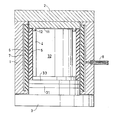
- The figure on the drawing schematically illustrates an axial section through an apparatus in accordance with the invention.
- The drawing figure illustrates an isostatic press including a
cylindrical jacket 1 with a fixedend structure 2 and aremovable end structure 3. On its inside thejacket 1 has anelastomeric jacket 6 behind which there is an annularhydraulic chamber 7. Thechamber 7 is pressurized and vented via a line 8. Thestructure 3 carries anelastomeric slab 31, in turn carrying anend wall 33 of a moulding tool. Thestructure 33 carries acore 32 and anelastomeric jacket 5. - On the inside of the fixed
end structure 2 of the press there is anend wall 11 with aprojection 12, which, together with theend wall 33, envelopingwall 5 andcore 32 defines a mould cavity 4 intended for filling with a powder from which a pressed body is to be formed. - The
elastomeric element 31 is contiguous to the radially deformable.elastomeric jacket 6 of the press. - During operation the press is kept together axially by a frame (not shown) on which the
end structures - When the
hydraulic chamber 7 is pressurized, the press frame is subjected to axial strain. Furthermore, theelastomeric jacket 6 moves radially inwards and exercises pressure against the elastomeric element.31. The diameter of theelement 31 is then reduced, its thickness accordingly increasing. Theelastomeric element 31 is dimensioned such that its increase in thickness corresponds to the strain in the press frame for a given selection of material for theelastomeric element 31. - It will be naturally understood that the
element 31 may be dimensioned such as to provide overcompensation of the press frame strain so that theend wall 33,exercises an active press pressure against the powder.mass in the mould cavity 4. - Although the
elastomeric element 31 has been illustrated disposed between theremovable end structure 3 of the press and theend wall 33 of the moulding tool built onto it, it should be quite clear that one can just as well arrange theelastomeric element 31 between the fixedpress end structure 2 and the associatedend wall 11. - It should also be clear that an elastomeric element can be arranged between the
end structure 3 andend wall 33 as well as between theend structure 2 and theend wall 11, both elements being dimensioned such as to provide together the desired degree of compensation for the axial elastic strain of the press frame in conjunction with its pressurization and pressure unloading.
Claims (5)
Priority Applications (1)
| Application Number | Priority Date | Filing Date | Title |
|---|---|---|---|
| AT83850287T ATE63264T1 (en) | 1982-11-09 | 1983-10-27 | DEVICE FOR COMPENSATING THE AXIAL DEFORMATION IN AN ISOSTATIC PRESS. |
Applications Claiming Priority (2)
| Application Number | Priority Date | Filing Date | Title |
|---|---|---|---|
| SE8206359 | 1982-11-09 | ||
| SE8206359A SE435353B (en) | 1982-11-09 | 1982-11-09 | DEVICE FOR COMPENSATING AXIAL TENSION OF AN ISOSTATIC PRESSURE |
Publications (3)
| Publication Number | Publication Date |
|---|---|
| EP0109949A2 true EP0109949A2 (en) | 1984-05-30 |
| EP0109949A3 EP0109949A3 (en) | 1985-08-28 |
| EP0109949B1 EP0109949B1 (en) | 1991-05-08 |
Family
ID=20348511
Family Applications (1)
| Application Number | Title | Priority Date | Filing Date |
|---|---|---|---|
| EP83850287A Expired - Lifetime EP0109949B1 (en) | 1982-11-09 | 1983-10-27 | Apparatus for compensing axial strain in an isostatic press |
Country Status (8)
| Country | Link |
|---|---|
| US (1) | US4564352A (en) |
| EP (1) | EP0109949B1 (en) |
| JP (1) | JPS59133992A (en) |
| AT (1) | ATE63264T1 (en) |
| AU (1) | AU566897B2 (en) |
| BR (1) | BR8306162A (en) |
| DE (1) | DE3382274D1 (en) |
| SE (1) | SE435353B (en) |
Cited By (2)
| Publication number | Priority date | Publication date | Assignee | Title |
|---|---|---|---|---|
| FR2750917A1 (en) * | 1996-11-18 | 1998-01-16 | Ceramiques Tech Soc D | Machine for making ceramic tubes |
| FR2757099A1 (en) * | 1997-12-15 | 1998-06-19 | Ceramiques Tech Soc D | Ceramic tube manufacturing equipment and procedure |
Families Citing this family (9)
| Publication number | Priority date | Publication date | Assignee | Title |
|---|---|---|---|---|
| EP0294519B1 (en) * | 1987-04-27 | 1993-03-24 | Inax Corporation | Dry-type powder pressing method and apparatus |
| US5749331A (en) * | 1992-03-23 | 1998-05-12 | Tecsyn, Inc. | Powdered metal cylinder liners |
| US5631029A (en) * | 1994-06-30 | 1997-05-20 | General Electric Company | Mould for isostatic pressing |
| DE4436854A1 (en) * | 1994-10-15 | 1996-04-18 | Ggu Gesundheits Umweltforsch | Drug supply for the mechanical release of respiratory active substance aerosols for the inhalation application of drugs |
| US5747073A (en) * | 1995-10-27 | 1998-05-05 | Tecsyn, Inc. | Apparatus for producing composite cylinders |
| US6299964B1 (en) * | 1998-09-01 | 2001-10-09 | Northrop Grumman Corporation | Flexible composite cure fixture |
| US8071016B2 (en) * | 2006-09-22 | 2011-12-06 | Gkn Sinter Metals Llc | Thin walled powder metal component manufacturing |
| TW200824874A (en) * | 2006-12-11 | 2008-06-16 | Sheng-Tzu Hsu | Air-tight mechanism used by the clasping apparatus to form the vacuum environment for the clasped mold |
| CN112060664B (en) * | 2020-09-03 | 2022-04-05 | 山西金开源实业有限公司 | Dry bag type isostatic pressing machine |
Citations (3)
| Publication number | Priority date | Publication date | Assignee | Title |
|---|---|---|---|---|
| US3832100A (en) * | 1973-01-05 | 1974-08-27 | Gleason Works | Tooling for receiving and supporting a quantity of powder material to be pressed into a self-supporting compact |
| US4046499A (en) * | 1973-08-16 | 1977-09-06 | Shinagawa Firebrick Co., Ltd. | Dry rubber compression molding apparatus |
| JPS5834102A (en) * | 1981-08-21 | 1983-02-28 | Hitachi Ltd | Powder molding device |
Family Cites Families (7)
| Publication number | Priority date | Publication date | Assignee | Title |
|---|---|---|---|---|
| JPS4313825Y1 (en) * | 1965-01-29 | 1968-06-12 | ||
| SE309293B (en) * | 1968-05-02 | 1969-03-17 | Asea Ab | |
| JPS4939871A (en) * | 1972-08-24 | 1974-04-13 | ||
| US3832103A (en) * | 1972-09-13 | 1974-08-27 | Nat Forge Co | Isostatic press |
| US3956452A (en) * | 1973-08-16 | 1976-05-11 | Shinagawa Firebrick, Co., Ltd. | Dry-type isostatic pressing method involving minimization of breaks or cracks in the molded bodies |
| US4056347A (en) * | 1976-12-27 | 1977-11-01 | Ab Carbox | Isostatic compactor of pulverulent materials and the like |
| FR2436120A1 (en) * | 1978-09-12 | 1980-04-11 | Basset Bretagne Loire | DEVICE AND METHOD FOR MANUFACTURING AGGLOMERATED POWDER ELEMENTS |
-
1982
- 1982-11-09 SE SE8206359A patent/SE435353B/en not_active IP Right Cessation
-
1983
- 1983-10-27 AT AT83850287T patent/ATE63264T1/en not_active IP Right Cessation
- 1983-10-27 DE DE8383850287T patent/DE3382274D1/en not_active Expired - Lifetime
- 1983-10-27 EP EP83850287A patent/EP0109949B1/en not_active Expired - Lifetime
- 1983-11-02 AU AU20908/83A patent/AU566897B2/en not_active Ceased
- 1983-11-07 JP JP58207665A patent/JPS59133992A/en active Granted
- 1983-11-09 BR BR8306162A patent/BR8306162A/en unknown
-
1985
- 1985-02-08 US US06/699,500 patent/US4564352A/en not_active Expired - Lifetime
Patent Citations (3)
| Publication number | Priority date | Publication date | Assignee | Title |
|---|---|---|---|---|
| US3832100A (en) * | 1973-01-05 | 1974-08-27 | Gleason Works | Tooling for receiving and supporting a quantity of powder material to be pressed into a self-supporting compact |
| US4046499A (en) * | 1973-08-16 | 1977-09-06 | Shinagawa Firebrick Co., Ltd. | Dry rubber compression molding apparatus |
| JPS5834102A (en) * | 1981-08-21 | 1983-02-28 | Hitachi Ltd | Powder molding device |
Non-Patent Citations (1)
| Title |
|---|
| PATENTS ABSTRACTS OF JAPAN, vol. 7, no. 112(M-215)(1257), 17th May 1983; & JP-A-58 034102 (HITACHI SEISAKUSHO K.K.) 28-02-1983 * |
Cited By (3)
| Publication number | Priority date | Publication date | Assignee | Title |
|---|---|---|---|---|
| FR2750917A1 (en) * | 1996-11-18 | 1998-01-16 | Ceramiques Tech Soc D | Machine for making ceramic tubes |
| EP0881061A1 (en) * | 1996-11-18 | 1998-12-02 | Societe Des Ceramiques Techniques | Device and process for making ceramic tubes |
| FR2757099A1 (en) * | 1997-12-15 | 1998-06-19 | Ceramiques Tech Soc D | Ceramic tube manufacturing equipment and procedure |
Also Published As
| Publication number | Publication date |
|---|---|
| AU2090883A (en) | 1984-05-17 |
| SE435353B (en) | 1984-09-24 |
| BR8306162A (en) | 1984-06-12 |
| EP0109949B1 (en) | 1991-05-08 |
| AU566897B2 (en) | 1987-11-05 |
| JPH0328277B2 (en) | 1991-04-18 |
| US4564352A (en) | 1986-01-14 |
| DE3382274D1 (en) | 1991-06-13 |
| EP0109949A3 (en) | 1985-08-28 |
| JPS59133992A (en) | 1984-08-01 |
| SE8206359L (en) | 1984-05-10 |
| ATE63264T1 (en) | 1991-05-15 |
| SE8206359D0 (en) | 1982-11-09 |
Similar Documents
| Publication | Publication Date | Title |
|---|---|---|
| EP0109949B1 (en) | Apparatus for compensing axial strain in an isostatic press | |
| EP0109948B1 (en) | A unit containing a moulding tool for semi-isostatic compaction of a powder contained in the press tool cavity | |
| US3832100A (en) | Tooling for receiving and supporting a quantity of powder material to be pressed into a self-supporting compact | |
| US3462797A (en) | Fabrication of elongated products | |
| US3671157A (en) | Die and punch assembly for compacting powder material | |
| US4056347A (en) | Isostatic compactor of pulverulent materials and the like | |
| KR100297192B1 (en) | Movable frame type press | |
| JPS642641B2 (en) | ||
| JPS56136234A (en) | Pressing device for bulging machine | |
| SU1359075A2 (en) | Die-casting mould for compacting powders | |
| SU827267A1 (en) | Press-mould for pressing powder articles | |
| JP3453408B2 (en) | Press device with clamping means | |
| RU2007276C1 (en) | Method for manufacturing articles from powder material in high-pressure chamber | |
| SU1232372A1 (en) | Split mould for hydrostatic compacting of metal powder | |
| JP3134188B2 (en) | Powder pressing equipment | |
| JPH0753937Y2 (en) | Hydrostatic press mold for ball forming | |
| JPH01119604A (en) | Powder molding method | |
| SU1433804A1 (en) | Injection mould for hydrostatic pressing of articles from powder materials | |
| JP2594691B2 (en) | Method of forming ceramic tube forming body | |
| JP3258515B2 (en) | Self-sealing high-pressure container | |
| JPS62199298A (en) | Powder press device | |
| SU1424970A1 (en) | Injection-mould for compacting articles from metallic powder | |
| JPS59215222A (en) | Method and device for increasing wall thickness of thin-walled cylindrical body | |
| SU451498A1 (en) | Device for forming powder products | |
| SU1741793A1 (en) | Process for production of receptacle sockets for limb prostheses |
Legal Events
| Date | Code | Title | Description |
|---|---|---|---|
| PUAI | Public reference made under article 153(3) epc to a published international application that has entered the european phase |
Free format text: ORIGINAL CODE: 0009012 |
|
| AK | Designated contracting states |
Designated state(s): AT BE CH DE FR GB IT LI LU NL SE |
|
| PUAL | Search report despatched |
Free format text: ORIGINAL CODE: 0009013 |
|
| AK | Designated contracting states |
Designated state(s): AT BE CH DE FR GB IT LI LU NL SE |
|
| 17P | Request for examination filed |
Effective date: 19860212 |
|
| 17Q | First examination report despatched |
Effective date: 19870729 |
|
| RAP1 | Party data changed (applicant data changed or rights of an application transferred) |
Owner name: CIPS AB |
|
| GRAA | (expected) grant |
Free format text: ORIGINAL CODE: 0009210 |
|
| AK | Designated contracting states |
Kind code of ref document: B1 Designated state(s): AT BE CH DE FR GB IT LI LU NL SE |
|
| PG25 | Lapsed in a contracting state [announced via postgrant information from national office to epo] |
Ref country code: SE Effective date: 19910508 Ref country code: NL Effective date: 19910508 Ref country code: LI Effective date: 19910508 Ref country code: CH Effective date: 19910508 Ref country code: AT Effective date: 19910508 |
|
| REF | Corresponds to: |
Ref document number: 63264 Country of ref document: AT Date of ref document: 19910515 Kind code of ref document: T |
|
| ITF | It: translation for a ep patent filed |
Owner name: BARZANO' E ZANARDO MILANO S.P.A. |
|
| REF | Corresponds to: |
Ref document number: 3382274 Country of ref document: DE Date of ref document: 19910613 |
|
| ET | Fr: translation filed | ||
| REG | Reference to a national code |
Ref country code: CH Ref legal event code: PL |
|
| NLV1 | Nl: lapsed or annulled due to failure to fulfill the requirements of art. 29p and 29m of the patents act | ||
| PG25 | Lapsed in a contracting state [announced via postgrant information from national office to epo] |
Ref country code: LU Free format text: LAPSE BECAUSE OF NON-PAYMENT OF DUE FEES Effective date: 19911031 |
|
| PLBE | No opposition filed within time limit |
Free format text: ORIGINAL CODE: 0009261 |
|
| STAA | Information on the status of an ep patent application or granted ep patent |
Free format text: STATUS: NO OPPOSITION FILED WITHIN TIME LIMIT |
|
| 26N | No opposition filed | ||
| REG | Reference to a national code |
Ref country code: GB Ref legal event code: IF02 |
|
| PGFP | Annual fee paid to national office [announced via postgrant information from national office to epo] |
Ref country code: GB Payment date: 20021003 Year of fee payment: 20 Ref country code: BE Payment date: 20021003 Year of fee payment: 20 |
|
| PGFP | Annual fee paid to national office [announced via postgrant information from national office to epo] |
Ref country code: DE Payment date: 20021004 Year of fee payment: 20 |
|
| PGFP | Annual fee paid to national office [announced via postgrant information from national office to epo] |
Ref country code: FR Payment date: 20021016 Year of fee payment: 20 |
|
| PG25 | Lapsed in a contracting state [announced via postgrant information from national office to epo] |
Ref country code: GB Free format text: LAPSE BECAUSE OF EXPIRATION OF PROTECTION Effective date: 20031026 |
|
| BE20 | Be: patent expired |
Owner name: *CIPS A.B. Effective date: 20031027 |
|
| REG | Reference to a national code |
Ref country code: GB Ref legal event code: PE20 |