EP0109689B1 - Vibratory sauna - Google Patents
Vibratory sauna Download PDFInfo
- Publication number
- EP0109689B1 EP0109689B1 EP83111659A EP83111659A EP0109689B1 EP 0109689 B1 EP0109689 B1 EP 0109689B1 EP 83111659 A EP83111659 A EP 83111659A EP 83111659 A EP83111659 A EP 83111659A EP 0109689 B1 EP0109689 B1 EP 0109689B1
- Authority
- EP
- European Patent Office
- Prior art keywords
- support member
- housing
- sauna
- heated air
- chamber
- Prior art date
- Legal status (The legal status is an assumption and is not a legal conclusion. Google has not performed a legal analysis and makes no representation as to the accuracy of the status listed.)
- Expired
Links
Images


Classifications
-
- A—HUMAN NECESSITIES
- A61—MEDICAL OR VETERINARY SCIENCE; HYGIENE
- A61H—PHYSICAL THERAPY APPARATUS, e.g. DEVICES FOR LOCATING OR STIMULATING REFLEX POINTS IN THE BODY; ARTIFICIAL RESPIRATION; MASSAGE; BATHING DEVICES FOR SPECIAL THERAPEUTIC OR HYGIENIC PURPOSES OR SPECIFIC PARTS OF THE BODY
- A61H33/00—Bathing devices for special therapeutic or hygienic purposes
- A61H33/06—Artificial hot-air or cold-air baths; Steam or gas baths or douches, e.g. sauna or Finnish baths
- A61H2033/061—Artificial hot-air baths
-
- A—HUMAN NECESSITIES
- A61—MEDICAL OR VETERINARY SCIENCE; HYGIENE
- A61H—PHYSICAL THERAPY APPARATUS, e.g. DEVICES FOR LOCATING OR STIMULATING REFLEX POINTS IN THE BODY; ARTIFICIAL RESPIRATION; MASSAGE; BATHING DEVICES FOR SPECIAL THERAPEUTIC OR HYGIENIC PURPOSES OR SPECIFIC PARTS OF THE BODY
- A61H35/00—Baths for specific parts of the body
- A61H2035/004—Baths for specific parts of the body for the whole body except the head
-
- A—HUMAN NECESSITIES
- A61—MEDICAL OR VETERINARY SCIENCE; HYGIENE
- A61H—PHYSICAL THERAPY APPARATUS, e.g. DEVICES FOR LOCATING OR STIMULATING REFLEX POINTS IN THE BODY; ARTIFICIAL RESPIRATION; MASSAGE; BATHING DEVICES FOR SPECIAL THERAPEUTIC OR HYGIENIC PURPOSES OR SPECIFIC PARTS OF THE BODY
- A61H2201/00—Characteristics of apparatus not provided for in the preceding codes
- A61H2201/01—Constructive details
- A61H2201/0119—Support for the device
- A61H2201/0138—Support for the device incorporated in furniture
- A61H2201/0142—Beds
-
- A—HUMAN NECESSITIES
- A61—MEDICAL OR VETERINARY SCIENCE; HYGIENE
- A61H—PHYSICAL THERAPY APPARATUS, e.g. DEVICES FOR LOCATING OR STIMULATING REFLEX POINTS IN THE BODY; ARTIFICIAL RESPIRATION; MASSAGE; BATHING DEVICES FOR SPECIAL THERAPEUTIC OR HYGIENIC PURPOSES OR SPECIFIC PARTS OF THE BODY
- A61H23/00—Percussion or vibration massage, e.g. using supersonic vibration; Suction-vibration massage; Massage with moving diaphragms
- A61H23/02—Percussion or vibration massage, e.g. using supersonic vibration; Suction-vibration massage; Massage with moving diaphragms with electric or magnetic drive
- A61H23/0254—Percussion or vibration massage, e.g. using supersonic vibration; Suction-vibration massage; Massage with moving diaphragms with electric or magnetic drive with rotary motor
- A61H23/0263—Percussion or vibration massage, e.g. using supersonic vibration; Suction-vibration massage; Massage with moving diaphragms with electric or magnetic drive with rotary motor using rotating unbalanced masses
Definitions
- This invention relates to a vibratory sauna in accordance with the preamble of claim 1.
- Hitherto conventional saunas have comprised a fixed housing having a hinged cover thereby allowing a person using the sauna to gain access.
- the person was usually treated to a passage of hot air or steam while being confined in the sauna housing and it was usually found that sauna treatment resulted in a user having a period of relaxation while the muscles and skin were subject to a "toning up" or gentle cleansing process.
- Saunas were also believed to improve blood circulation.
- a vibratory sauna according to the preamble of claim 1 is known.
- the support member is supported only at one central location by a rod which is subject to the action of the vibration means associated with a motor.
- This arrangement may produce a jerky uncontrolled vibration, because the chair is only supported at one location. No means is foreseen to generate an air flow. Therefore hot spots may occur.
- a heating apparatus for treating patients. No vibration means is provided and flow of the heated air is only uncontrolled, essentially transversely through the apparatus.
- the vibratory sauna of the invention is characterized by the features of the characterizing portion of claim 1.
- the sauna shown in the drawings includes a sauna housing 10 having a support frame 11 including support legs 12 and a peripheral frame member 13. Hingedly attached to housing 10 is a cover 14 broken away in FIG. 1 to show a person 15 resting on support plate 16. There is also shown a head support or pillow 17, thermometer 18 and control panel 19.
- Cover 14 includes a peripheral flange 20 for engaging with peripheral frame member 13 and a head opening 21 as well as handle 22.
- Hinges 23 interconnect flange 20 and frame member 13 as shown in FIG. 2.
- Chains 24 also interconnect cover 14 and sauna housing 10.
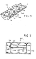
- FIG. 3 there is shown a trough 10A which is a basic component of sauna housing 10 having chamber 10B wherein the black arrows indicate the flow path of the hot air circulating therein.
- transverse baffles 25, 26 and 27 Baffles 25 and 27 are useful for mounting of fans 28 and central baffle 26 is utilized for mounting of heating element 30.
- End baffle 31 is used to deflect air flow upwardly as shown.
- lower mounting members 32 having recesses 33 for balls 34 which also engage in recesses 35 of upper mounting members 36 attached to the underside of support plate 16.
- the support member 16 also includes an electric motor 37 bolted to the underside thereof having an output shaft 38. Attached to output shaft 38 is a mounting plate 39 having vibration member or eccentric 40 attached thereto. Vibration of member 40 upon rotation of shaft 38 in turn causes vibration of support plate 16 which is resiliently mounted on balls 34 as described previously. This provides a gentle vibration which has a soothing and relaxing effect on the person using the sauna and hence for this reason it is believed that the vibrating sauna of the invention is an advance over the prior art.
- FIG. 7 there is shown a modified trough 10C having chamber 10D contained therein.
- mounting sockets 33B located in brackets or lugs 32B for balls or pads 34 described previously.
- tunnel 41 having fan or blower 28B located in one end in partition 25B as shown.
- electrical socket 30B for activation of a heating element (not shown) in tunnel 41 and another electrical socket 42 for activation of fan 28B.
- the vibratory sauna of the invention is also useful in that the person 15 may have tired muscles and wound up nerves relaxed in the gentle massage of the sensual vibration and passive heat combinations.
- the vibratory sauna of the invention is a unique concept and works on the principle of heating the body while the vibration stimulates body movement giving the simulated effect of exercising.
- the vibratory sauna of the invention may be programmed to simulate the results of a jog or brisk walk.
- the principle of the invention is help in the breakdown of fat cells and the removal of surplus body fluids.
- Therapeutic effects such as relief from backache, tired muscles, arthritis, tension, soreness and insomnia may also be achieved by the vibratory sauna of the invention.
- the support member 16 is spaced from the peripheral flange 13 by spaces 43 and 44 so as to facilitate the continuous circulation of heated air previously described.
Description
- This invention relates to a vibratory sauna in accordance with the preamble of claim 1.
- Hitherto conventional saunas have comprised a fixed housing having a hinged cover thereby allowing a person using the sauna to gain access. The person was usually treated to a passage of hot air or steam while being confined in the sauna housing and it was usually found that sauna treatment resulted in a user having a period of relaxation while the muscles and skin were subject to a "toning up" or gentle cleansing process. Saunas were also believed to improve blood circulation.
- In another type of sauna a person was subject to a steam bath in a room heated to above average temperature.
- In yet another type of sauna a person could relax in a shallow bath while having pressurized jets of water directed at various parts of his body.
- While these conventional saunas as described above have been found to be generally satisfactory, disadvantages that were found including the user of the sauna not being able to experience complete relaxation because of the fact that his body was normally stationary and often a cramped feeling resulted. This normally meant the user frequently changing his position in relation to the latter type of saunas described above and only remaining in the first type of conventional sauna as described above for a relatively short period of time.
- From the GB-A-1,129,306 a vibratory sauna according to the preamble of claim 1 is known. In this vibratory sauna the support member is supported only at one central location by a rod which is subject to the action of the vibration means associated with a motor. This arrangement may produce a jerky uncontrolled vibration, because the chair is only supported at one location. No means is foreseen to generate an air flow. Therefore hot spots may occur.
- From the FR-A-962,314 or FR-E-59,356 a heating apparatus is known for treating patients. No vibration means is provided and flow of the heated air is only uncontrolled, essentially transversely through the apparatus.
- It is therefore an object of the invention to provide a vibratory sauna as described above which alleviates the above-mentioned difficulties associated with the prior art, which especially imparts a gentle vibration to the support member and according to a preferred embodiment forces the air flow to be longitudinal through the vibratory sauna.
- The vibratory sauna of the invention is characterized by the features of the characterizing portion of claim 1.
- Further details of the invention are given in the subclaims.
- Reference may now be made to a preferred embodiment of the invention as shown in the attached drawings wherein:
- FIG. 1 is a perspective view of a sauna constructed in accordance with the invention in an operative position;
- FIG. 2 is a perspective view of the sauna shown in FIG. 1 in an inoperative position;
- FIG. 3 is a perspective view of the sauna shown in FIG. 1 with the support member removed for cfarity;
- FIG. 4 is a detailed view of the support member;
- FIG. 5 is a detailed view of the resilient mounting means utilized to mount the support member within the sauna housing;
- FIG. 6 is a detailed view of the vibration means; and
- FIG. 7 is a plan view of a modified sauna constructed in accordance with the invention with the support member removed for clarity.
- The sauna shown in the drawings includes a
sauna housing 10 having asupport frame 11 includingsupport legs 12 and aperipheral frame member 13. Hingedly attached tohousing 10 is acover 14 broken away in FIG. 1 to show aperson 15 resting onsupport plate 16. There is also shown a head support orpillow 17,thermometer 18 andcontrol panel 19. -
Cover 14 includes aperipheral flange 20 for engaging withperipheral frame member 13 and a head opening 21 as well ashandle 22. Hinges 23interconnect flange 20 andframe member 13 as shown in FIG. 2. Chains 24 also interconnectcover 14 andsauna housing 10. - In FIG. 3 there is shown a
trough 10A which is a basic component ofsauna housing 10 having chamber 10B wherein the black arrows indicate the flow path of the hot air circulating therein. There is also providedtransverse baffles fans 28 andcentral baffle 26 is utilized for mounting ofheating element 30.End baffle 31 is used to deflect air flow upwardly as shown. There is also providedlower mounting members 32 havingrecesses 33 forballs 34 which also engage inrecesses 35 ofupper mounting members 36 attached to the underside ofsupport plate 16. - The
support member 16 also includes anelectric motor 37 bolted to the underside thereof having anoutput shaft 38. Attached tooutput shaft 38 is amounting plate 39 having vibration member or eccentric 40 attached thereto. Vibration ofmember 40 upon rotation ofshaft 38 in turn causes vibration ofsupport plate 16 which is resiliently mounted onballs 34 as described previously. This provides a gentle vibration which has a soothing and relaxing effect on the person using the sauna and hence for this reason it is believed that the vibrating sauna of the invention is an advance over the prior art. - In FIG. 7 there is shown a modified trough
10C having chamber 10D contained therein. There is also shownmounting sockets 33B located in brackets orlugs 32B for balls orpads 34 described previously. Also shown istunnel 41 having fan orblower 28B located in one end inpartition 25B as shown. Also shown is theother end partition 27B oftunnel 41. There is also shownelectrical socket 30B for activation of a heating element (not shown) intunnel 41 and anotherelectrical socket 42 for activation offan 28B. - The vibratory sauna of the invention is also useful in that the
person 15 may have tired muscles and wound up nerves relaxed in the gentle massage of the sensual vibration and passive heat combinations. - The vibratory sauna of the invention is a unique concept and works on the principle of heating the body while the vibration stimulates body movement giving the simulated effect of exercising. Depending upon the metabolism of the user the vibratory sauna of the invention may be programmed to simulate the results of a jog or brisk walk. Thus the vibratory sauna of the invention is to assist people unable to participate in active exercise. The principle of the invention is help in the breakdown of fat cells and the removal of surplus body fluids. Therapeutic effects such as relief from backache, tired muscles, arthritis, tension, soreness and insomnia may also be achieved by the vibratory sauna of the invention.
- It will also be noted from the drawings that the
support member 16 is spaced from theperipheral flange 13 byspaces
Claims (8)
Applications Claiming Priority (4)
| Application Number | Priority Date | Filing Date | Title |
|---|---|---|---|
| AUPF693582 | 1982-11-23 | ||
| AU6935/82 | 1982-11-23 | ||
| AU29265/84A AU539484B3 (en) | 1982-11-23 | 1984-06-12 | Vibratory sauna |
| AU34698/84A AU542750B3 (en) | 1982-11-23 | 1984-10-25 | Improved sauna |
Publications (2)
| Publication Number | Publication Date |
|---|---|
| EP0109689A1 EP0109689A1 (en) | 1984-05-30 |
| EP0109689B1 true EP0109689B1 (en) | 1987-07-29 |
Family
ID=27153235
Family Applications (1)
| Application Number | Title | Priority Date | Filing Date |
|---|---|---|---|
| EP83111659A Expired EP0109689B1 (en) | 1982-11-23 | 1983-11-22 | Vibratory sauna |
Country Status (3)
| Country | Link |
|---|---|
| US (1) | US4565188A (en) |
| EP (1) | EP0109689B1 (en) |
| AU (2) | AU539484B3 (en) |
Families Citing this family (27)
| Publication number | Priority date | Publication date | Assignee | Title |
|---|---|---|---|---|
| US4712538A (en) * | 1982-11-23 | 1987-12-15 | Hardie Laurie S | Vibratory sauna |
| US4671284A (en) * | 1986-08-01 | 1987-06-09 | Vibrosaun Usa, Inc. | Sauna support bed |
| JPS63238864A (en) * | 1987-03-26 | 1988-10-04 | 株式会社イナックス | Steam sauna |
| DE3718665A1 (en) * | 1987-06-04 | 1988-12-22 | Sana Plus Gmbh | DEVICE FOR CARRYING OUT THERMAL TREATMENTS OF THE HUMAN BODY |
| FR2629343B1 (en) * | 1988-03-29 | 1990-07-06 | Diot Jean | INDIVIDUAL SAUNA FOR VIBRATION MASSAGES IN CONDITIONED ATMOSPHERE |
| GB2219203A (en) * | 1988-06-04 | 1989-12-06 | Cpd Centre For Patent Dev Limi | Apparatus for treating a person's body |
| US5027797A (en) * | 1989-10-12 | 1991-07-02 | Horace Bullard | Apparatus for the movement of blood by external pressure |
| US5101809A (en) * | 1990-04-13 | 1992-04-07 | Sybaritic, Inc. | Vibratory sauna |
| US5069207A (en) * | 1990-07-23 | 1991-12-03 | Lin Shin Hsiung | Physiotherapy healthy device |
| DE4024664A1 (en) * | 1990-08-03 | 1992-02-06 | Mueller Quarzlampenfab Dr F | Apparatus for treating patient with infrared and ultraviolet radiation - has vibrating couch to support patient, with head end and body support which can be vibrated |
| US5441529A (en) * | 1994-09-06 | 1995-08-15 | Dorsch; Erwin | Therapeutic bathing apparatus |
| US5645578A (en) * | 1994-11-16 | 1997-07-08 | Sybaritic, Inc. | Total therapy sauna bed system |
| IT1284402B1 (en) * | 1995-07-21 | 1998-05-18 | Margherita Tron | MOTOR ACTIVITY TABLE FOR AESTHETIC AND SLIMMING TREATMENTS |
| USD384416S (en) * | 1995-11-13 | 1997-09-30 | Visibelle Derma Institute, Inc. | Personal sauna with lighted hood |
| US5891186A (en) * | 1995-11-15 | 1999-04-06 | Visibelle Derma Institute, Inc. | Physical therapy heated personal capsule |
| USD377530S (en) * | 1995-11-15 | 1997-01-21 | Visibelle Derma Institute, Inc. | Physical therapy heated capsule |
| US6497717B1 (en) | 1999-04-12 | 2002-12-24 | Visibelle Derma Institute, Inc. | Therapy steam and heat treatment cabinet |
| US6623511B1 (en) | 1999-04-12 | 2003-09-23 | Visibelle Derma Institute, Inc. | Chromatherapy shower system |
| KR200163301Y1 (en) * | 1999-07-02 | 2000-02-15 | 박민화 | Portable sauna vessel |
| US6363559B1 (en) | 1999-08-18 | 2002-04-02 | Warmkraft, Inc. | Massage motor mounting assembly |
| USD433144S (en) * | 2000-02-01 | 2000-10-31 | Park Min H | Personal sauna |
| US6339854B1 (en) * | 2000-09-21 | 2002-01-22 | Spa Logic Inc. | Steam cabinet and method of manufacture |
| US7503926B2 (en) * | 2003-05-09 | 2009-03-17 | Visibelle Derma Institute, Inc. | Combined sauna and environmental capsule |
| US9808644B2 (en) | 2008-03-03 | 2017-11-07 | Visibelle Derma Institute, Inc. | Capsule with whole body LED photo-therapy system |
| USD668768S1 (en) * | 2011-06-15 | 2012-10-09 | Geoffrey Edmund Hooper | Foot bath |
| US11311410B2 (en) | 2017-06-19 | 2022-04-26 | Visibelle Derma Institute, Inc. | Hyperthermic conditioning capsule |
| AU2019336505B2 (en) * | 2018-09-03 | 2021-11-04 | Torsten Sauer | Outdoor furniture |
Family Cites Families (13)
| Publication number | Priority date | Publication date | Assignee | Title |
|---|---|---|---|---|
| US1797153A (en) * | 1930-08-15 | 1931-03-17 | Nogradi Mihaly | Vapor-bath cabinet |
| US2096128A (en) * | 1936-04-18 | 1937-10-19 | Jr William E Mortrude | Electrophysical cabinet |
| US2235184A (en) * | 1939-10-25 | 1941-03-18 | William L Wettlaufer | Therapeutic vibrator |
| US2500508A (en) * | 1946-06-25 | 1950-03-14 | Bachin Peter | Physical therapeutic table |
| FR1004574A (en) * | 1947-05-10 | 1952-03-31 | Apparatus for electrical treatments by physical agents | |
| FR953108A (en) * | 1947-09-12 | 1949-11-30 | Electric sweat machine | |
| FR59356E (en) * | 1948-02-05 | 1954-05-25 | Sweat device | |
| FR962314A (en) * | 1948-02-05 | 1950-06-07 | ||
| FR984857A (en) * | 1949-04-20 | 1951-07-11 | Apparatus for treatment with physical agents, such as light or heat baths | |
| US2814297A (en) * | 1955-02-15 | 1957-11-26 | Enos A Stewart | Dry air therapeutic cabinet |
| FR1430933A (en) * | 1964-12-07 | 1966-03-11 | Boosting device, relaxation chair, vibrating | |
| US3826250A (en) * | 1972-07-12 | 1974-07-30 | Zany Prod Inc | Apparatus |
| DE2406648A1 (en) * | 1972-08-04 | 1975-08-21 | Rene Simon | DEVICE FOR BODY TREATMENT UNDER SWEATS |
-
1983
- 1983-11-15 US US06/551,958 patent/US4565188A/en not_active Expired - Fee Related
- 1983-11-22 EP EP83111659A patent/EP0109689B1/en not_active Expired
-
1984
- 1984-06-12 AU AU29265/84A patent/AU539484B3/en not_active Ceased
- 1984-10-25 AU AU34698/84A patent/AU542750B3/en not_active Expired
Also Published As
| Publication number | Publication date |
|---|---|
| US4565188A (en) | 1986-01-21 |
| EP0109689A1 (en) | 1984-05-30 |
| AU542750B3 (en) | 1985-04-18 |
| AU539484B3 (en) | 1984-10-11 |
Similar Documents
| Publication | Publication Date | Title |
|---|---|---|
| EP0109689B1 (en) | Vibratory sauna | |
| US4671284A (en) | Sauna support bed | |
| US4947832A (en) | Apparatus and method for treating or relieving colicky infants | |
| US5729841A (en) | Foot-massager | |
| EP0525130B1 (en) | Vibratory sauna | |
| US6805678B2 (en) | Apparatus for foot therapy | |
| US2943620A (en) | Pillow or cushion type vibrator | |
| US6997889B1 (en) | Electric massage comb | |
| KR101453593B1 (en) | Portable massage device | |
| WO2007113875A1 (en) | Body treatment and anti-ageing apparatus | |
| US4633858A (en) | Massage device with pinching action | |
| US2765786A (en) | Massage unit | |
| US3169521A (en) | Orbiting massage machine | |
| US3292614A (en) | Roller massaging device with means for spraying water between the rollers | |
| CA1223165A (en) | Vibratory sauna | |
| JP3700058B2 (en) | Underwater vibration wave generation bathtub | |
| EP1191917B1 (en) | Bath equipped with water vibrator | |
| KR200180410Y1 (en) | Cool water and hot water treatment system | |
| US2827044A (en) | Portable massaging apparatus | |
| CN109464278A (en) | A kind of Neurology lower limb physical therapy device | |
| KR100735847B1 (en) | A Multi Complex Foot Bathtub | |
| KR100537556B1 (en) | Massage device for neck and head | |
| JPS642760Y2 (en) | ||
| KR20060005992A (en) | A steam foot bath machine | |
| JPS61141365A (en) | Sauna with vibrator |
Legal Events
| Date | Code | Title | Description |
|---|---|---|---|
| PUAI | Public reference made under article 153(3) epc to a published international application that has entered the european phase |
Free format text: ORIGINAL CODE: 0009012 |
|
| AK | Designated contracting states |
Designated state(s): DE FR GB IT NL SE |
|
| 17P | Request for examination filed |
Effective date: 19841116 |
|
| 17Q | First examination report despatched |
Effective date: 19860324 |
|
| GRAA | (expected) grant |
Free format text: ORIGINAL CODE: 0009210 |
|
| AK | Designated contracting states |
Kind code of ref document: B1 Designated state(s): DE FR GB IT NL SE |
|
| REF | Corresponds to: |
Ref document number: 3372702 Country of ref document: DE Date of ref document: 19870903 |
|
| ET | Fr: translation filed | ||
| ITF | It: translation for a ep patent filed |
Owner name: SAIC BREVETTI S.R.L. |
|
| PLBE | No opposition filed within time limit |
Free format text: ORIGINAL CODE: 0009261 |
|
| STAA | Information on the status of an ep patent application or granted ep patent |
Free format text: STATUS: NO OPPOSITION FILED WITHIN TIME LIMIT |
|
| 26N | No opposition filed | ||
| ITTA | It: last paid annual fee | ||
| EAL | Se: european patent in force in sweden |
Ref document number: 83111659.5 |
|
| REG | Reference to a national code |
Ref country code: GB Ref legal event code: IF02 |
|
| PGFP | Annual fee paid to national office [announced via postgrant information from national office to epo] |
Ref country code: NL Payment date: 20021029 Year of fee payment: 20 |
|
| PGFP | Annual fee paid to national office [announced via postgrant information from national office to epo] |
Ref country code: GB Payment date: 20021112 Year of fee payment: 20 |
|
| PGFP | Annual fee paid to national office [announced via postgrant information from national office to epo] |
Ref country code: FR Payment date: 20021118 Year of fee payment: 20 |
|
| PGFP | Annual fee paid to national office [announced via postgrant information from national office to epo] |
Ref country code: SE Payment date: 20021122 Year of fee payment: 20 |
|
| PGFP | Annual fee paid to national office [announced via postgrant information from national office to epo] |
Ref country code: DE Payment date: 20021202 Year of fee payment: 20 |
|
| PG25 | Lapsed in a contracting state [announced via postgrant information from national office to epo] |
Ref country code: GB Free format text: LAPSE BECAUSE OF EXPIRATION OF PROTECTION Effective date: 20031121 |
|
| PG25 | Lapsed in a contracting state [announced via postgrant information from national office to epo] |
Ref country code: NL Free format text: LAPSE BECAUSE OF EXPIRATION OF PROTECTION Effective date: 20031122 |
|
| REG | Reference to a national code |
Ref country code: GB Ref legal event code: PE20 |
|
| EUG | Se: european patent has lapsed | ||
| NLV7 | Nl: ceased due to reaching the maximum lifetime of a patent |
Effective date: 20031122 |