EP0109440B1 - Multiple location storage bays - Google Patents
Multiple location storage bays Download PDFInfo
- Publication number
- EP0109440B1 EP0109440B1 EP83902155A EP83902155A EP0109440B1 EP 0109440 B1 EP0109440 B1 EP 0109440B1 EP 83902155 A EP83902155 A EP 83902155A EP 83902155 A EP83902155 A EP 83902155A EP 0109440 B1 EP0109440 B1 EP 0109440B1
- Authority
- EP
- European Patent Office
- Prior art keywords
- trolley
- location
- catch
- bay
- load
- Prior art date
- Legal status (The legal status is an assumption and is not a legal conclusion. Google has not performed a legal analysis and makes no representation as to the accuracy of the status listed.)
- Expired
Links
- 230000009977 dual effect Effects 0.000 claims description 2
- 230000005484 gravity Effects 0.000 description 4
- 230000007246 mechanism Effects 0.000 description 4
- 238000006073 displacement reaction Methods 0.000 description 3
- 238000003491 array Methods 0.000 description 2
- 230000000712 assembly Effects 0.000 description 2
- 238000000429 assembly Methods 0.000 description 2
- 238000010276 construction Methods 0.000 description 2
- 238000000034 method Methods 0.000 description 2
- 238000005096 rolling process Methods 0.000 description 2
- 229910000746 Structural steel Inorganic materials 0.000 description 1
- 230000004913 activation Effects 0.000 description 1
- 230000006835 compression Effects 0.000 description 1
- 238000007906 compression Methods 0.000 description 1
- 210000004185 liver Anatomy 0.000 description 1
- 239000002184 metal Substances 0.000 description 1
- 229910052751 metal Inorganic materials 0.000 description 1
- 238000011084 recovery Methods 0.000 description 1
- 239000012858 resilient material Substances 0.000 description 1
- 229920003051 synthetic elastomer Polymers 0.000 description 1
- 239000005061 synthetic rubber Substances 0.000 description 1
- 230000000007 visual effect Effects 0.000 description 1
Images


Classifications
-
- B—PERFORMING OPERATIONS; TRANSPORTING
- B65—CONVEYING; PACKING; STORING; HANDLING THIN OR FILAMENTARY MATERIAL
- B65G—TRANSPORT OR STORAGE DEVICES, e.g. CONVEYORS FOR LOADING OR TIPPING, SHOP CONVEYOR SYSTEMS OR PNEUMATIC TUBE CONVEYORS
- B65G1/00—Storing articles, individually or in orderly arrangement, in warehouses or magazines
- B65G1/02—Storage devices
- B65G1/026—Racks equipped with a displaceable load carrying surface to facilitate loading or unloading
-
- B—PERFORMING OPERATIONS; TRANSPORTING
- B65—CONVEYING; PACKING; STORING; HANDLING THIN OR FILAMENTARY MATERIAL
- B65G—TRANSPORT OR STORAGE DEVICES, e.g. CONVEYORS FOR LOADING OR TIPPING, SHOP CONVEYOR SYSTEMS OR PNEUMATIC TUBE CONVEYORS
- B65G1/00—Storing articles, individually or in orderly arrangement, in warehouses or magazines
- B65G1/02—Storage devices
- B65G1/04—Storage devices mechanical
- B65G1/06—Storage devices mechanical with means for presenting articles for removal at predetermined position or level
Definitions
- the present invention relates to warehouse storage arrangements and more particularly to storage racks having superimposed bays for each holding multiple loads of goods.
- a convenient method of warehousing goods is to stack goods on pallets and insert the loaded pallets into storage bays using fork lift trucks or the like.
- a common warehouse arrangement has a pair of back-to-back arrays with each array facing an aisle.
- Each array includes a plurality of storage bays in horizontal and vertical rows. It is recognized that a warehousing arrangement which requires one aisle for two arrays, each one load deep, is wasteful of floor space, and storage racks have been proposed having greater depth whereby loads may be stored at more than one location within each bay.
- U.S. Patent No. 4,155,462 discloses storage racks for receiving two loads of palleted goods through a front end, thereby essentially doubling the amount of storage area associated with each aisle.
- a first load of goods is placed upon a trolley in the storage bay, and the loaded trolley is moved rearward along a track to an inner location when a second load is inserted in the same bay.
- the trolley which is biased forward by resilient means, returns its load to the front location of the bay when the second load is removed.
- GB-A-2 024 179 discloses a trolley storage rack system in which a forward load prevents a trolley to the rear of the load from suffering forward displacement under gravity. Doring, however, proposes no solution to the problem of inadvertent displacement of a forward trolley into the aisle as a result of gradual removal of its load and consequent reduction in its capacity to restrain the rear trolley.
- US-A-3757967 discloses an arrangement in which a movable bridge allows a dolly to be rolled from one rack to another on the opposite side of the bridge.
- a plurality of plungers are normally spring-loaded so as to be biased to their raised positions in which they obstruct passage of the dollies by serving as an obstacle, within the path of the dollies, to the dolly front channel section. Moving the bridge into position using an overhead hoist causes angle iron members carried by the bridge to depress the plungers so that they cease to obstruct the dollies.
- US-A-3895724 discloses a barrel-storage rack so constructed that only one barrel or drum at a time is rolled along a track or rail for discharge to a vertical chute.
- a roller is raised in use to form a track obstruction to a second drum by activation of a stop arm device by the first drum.
- a release mechanism is provided in order to release the first drum to the chute.
- a trolley of a rack storage system is restrained from forward displacement by relatively simple means of the trolley, such means being cooperative with derailment-prevention means of the apparatus as well as with means enabling the restraint means of the trolley to fulfil its function.
- a storage rack is provided by the invention for receiving at least two loads in a front location and at least one location rearward thereof, each bay comprising an open front end through which loads may be supplied and withdrawn, rail means extending from said front location to said rearward location and being inclined downward towards said front end, trolley means for carrying a load, said trolley means being mounted on said rail means for movement therealong and having means for supporting a load at said front location when said trolley is moved to said rearward location and catch means associated with said rail means for preventing forward movement of said trolley means when in said rearward location, characterised in that said catch means includes a vertically extending tang for engaging retainer means and means to release said catch means by rotating said tang out of engagement therewith, and in that said retainer means extends laterally outward
- the improved storage rack of the invention has bays which each hold three loads of goods.
- Each bay has an outer track and an inner track which run from its open front end rearward and carry an upper trolley and a telescoping lower trolley.
- a first load is placed on the upper trolley which is later moved rearward when a fork-lift truck de-, livers a second loaded pallet and places it on the lower trolley. Both loads are later moved rearward as a third load of goods is placed upon ⁇ l a ual am
- the catch means referred to earlier are associated with the outer and inner tracks and hold the upper and lower trolleys at the center location of the bay until released.
- Hold-down brackets constitute the flange means referred to and serves to prevent the trolleys from derailing.
- a storage rack assembly which includes a plurality of fore-and-aft extending frames 2 that are formed from vertical posts 4 rigidly interconnected by X-bracing 5 and straight braces 6.
- the frames 2 are connected by longitudinal beams or stringers 7 into a three-dimensional, stable framework or rack structure which may extend from the floor to the roof of a warehouse and provides a number of superimposed storage locations.
- a large number of parallel frames 2 are used, which are uniformly spaced from one another by the stringers 7 to create a large number of vertical rows, each of which includes several superimposed storage bays 10.
- a single bay 10 is shown which is defined on each lateral side by a pair of aligned frames 2 that may be linked together by tie bars 11 or may be interconnected only by the tracks as described hereinafter.
- Each bay is capable of holding three loads of goods: one load 12a carried by an upper trolley 14 at the rear end of the bay, one load 12b carried by a lower trolley 16 at the center of the bay and one load 12c supported on a track assembly 20 for the trolleys or upon a pair a cross supports 22 (Fig. 6) at the front location of the bay.
- the trolleys are movable along the track assembly 20 from the front of the bay rearward to allow successive loads to be supplied through the open front end of the bay which is at the lefthand edge of Fig. 1.
- each horizontally extending storage bay 10 can store three pallet loads 12 of goods and includes an outer track 24 and an inner track 26 extending from the front end rearward, along which the telescoped upper and lower trolleys 14, 16 travel independently of each other.
- a first load 12a is placed on the upper trolley 14.
- the loaded upper trolley is moved or pushed rearward as a second load 12b of goods is inserted and placed on the lower trolley 16.
- a third load 12c is inserted through the front end of the track assembly 20
- both loaded trolleys are pushed rearward, with the upper trolley 14 moving to a rear location in the bay and the lower trolley 16 to a central location.
- the procedure is reversed.
- the track assembly 20 is inclined downward toward the front end of the bay whereby gravity causes the trolleys 14, 16 to tend to roll toward the front; however, catches 28a, 28b associated with the track assembly 20 prevent a trolley from moving forward from the central location until released.
- Release means 30a, 30b (Fig. 2) upon actuation disengage the appropriate catch 28a, 28b allowing one or both of the trolleys to roll forward along the track assembly.
- the superimposed bays 10 of the storage rack assembly are generally defined by the track assemblies that are supported from the vertical frames 2 and the horizontal stringers 7.
- the width of each bay 10 is somewhat greater than the width of a standard pallet 36.
- Each bay has sufficient height to accommodate a loaded pallet carried upon the upper trolley and is slightly greater than 3 pallets deep.
- the trolleys 14, 16 are preferably formed of welded-together tubular members of rectangular cross section and are designed to facilitate the support of a standard pallet thereatop. Wheels 40 of the trolleys rotate on axles 78 mounted in short vertical tubular members 39 at the four corners, and the two corner tubular members 39 on each lateral side are interconnected by lateral tubular members 38.
- the lateral tubular members 38 are interconnected by cross tubular pieces 41 having upper surfaces at the same level as the upper surfaces of the lateral tubular members 38, thereby defining a load-supporting surface.
- Loads 12 disposed on pallets 36 having their fork-entry openings facing fore-and-aft are supported on the upper surfaces of the tubular members 38 and 41. Decking (not shown) can be applied atop the tubular members should it be desired to store loads disposed on slip-sheets or the like.
- the track assembly 20 includes a pair of tubular beams or rails 44 extending fore-and-aft for generally the length of the bay which rails are mounted on the horizontal stringers 7.
- Upwardly open C-shaped channel sections 42 which are more than twice as wide as the rails (Fig. 3), serve a hold-down function and are placed at the front end of each rail and at a strategic central location within.
- the inner and outer edges of the top surfaces of the rails 44 provide the inner and outer tracks 26, 24 along which the wheels 40 of the lower and upper trolleys 16, 14 roll, and the channels 42 interengage with hold-down brackets or retainers 46 carried by the trolleys to prevent derailment of the trolleys during loading or unloading of a palletized load by a fork lift or the like.
- each of the rails 44 has rounded edges
- each of the wheels 40 has a flange 50 which extends below the upper surface and along the side of the rail and has a rolling surface 52 matched to the rounded edge of the rail.
- the flanges 50 of the upper trolley wheels 40 lie laterally outward with respect to the track assembly while the flanges 50' of the lower trolley wheels 40' lie inward.
- the hold-down channels 42 are placed at the positions of the wheels 40 at the front trolley location.
- Each C-shaped channel 42 has a lower web 53, which is disposed between the undersurface of a rail 44 and one of the horizontal stringers 7, a pair of upstanding flanges 56 at the lateral edges thereof and a pair of inturned edges 58.
- the inturned edges 58 of each channel are generally at the horizontal level of the upper surface of the rail and are spaced laterally from the rail 44 providing a pair of slots 62 along each side of the rail which accommodate the wheel flanges 50 and hold-down brackets 46.
- the hold-down brackets 46 depend from the lower edges of each rectangular tube member 39 in which the wheels 40 are mounted, and each terminates in an horizontal section 68 which is located under the corresponding inturned edge 58 of channel 42.
- the hold-down brackets 46 prevent derailment of a trolley which may inadvertently result during loading or unloading by a fork-lift truck or the like because the horizontal sections 68 at each of the four corners of both trolleys are under the inturned flanges 58 when they are in the front location, and the possibility of the trolley wheel bounding off of the track during supply of a load which might be dropped onto eithertrolley is also eliminated.
- the track assembly 20 is preferably inclined downward toward the front at an angle of between about 3° and about 6°.
- Each of the trolleys rolls by gravity along the inclined track assembly until the trolley in the front location hits spring-loaded bumpers 74 (Fig. 5 and 7) at the front of the track assembly 20.
- the bumpers 74 include socket-head shoulder bolts 74a which fit thru openings provided in front end brackets 75 that are welded or suitably otherwise affixed to the C-shaped channels 42. The bolts screw into tapped holes in rectangular pads 74b, and compression springs 74c surround the bolts 74a. Two bumpers are within each of the front channel sections 42 in flanking relationship to the front end of each rail 44.
- brake means to slow down the trolleys may optionally be provided in the form of hysteresis wheels 76 in contact with each of the trolley wheels 40.
- Each of the trolley wheels 40 is mounted on an independent axle 78 supported from the lateral sides of the rectangular tubular member 39, and an associated hysteresis wheel 76 is mounted on an axle 80 similarly supported in the lateral sides of the tubular member 39.
- the hysteresis wheels 76 are formed of soft, resilient material, such as a soft synthetic rubber, and are mounted to press against the rolling surfaces of the metal trolley wheels 40 as they turn but mounted so as not to contact the track surface.
- the pressure of the hysteresis wheels is sufficient to retard the trolleys from accelerating.
- the slope of the track can be lowered slightly so the trolleys will not have a tendency to move quite as fast, and in this respect, the stringers 7 are preferably mounted upon the posts 4 with infinitely adjustable connectors 81 (Figs. 2 and 3) of the type described in U.S. Patent No. 3,877,579, issued April 15,1975 to John J. Weider, see Fig. 2.
- the present invention employs a positive catch 28 to maintain a trolley in the center position until released. These positive catches assure that the trolleys will not push a load disposed in the front position into the aisle. This feature is particularly important when items of goods are picked one-by-one from the pallets 36 in the front location rather than withdrawn only by pallet load.
- a preferred catch-release mechanism cooperates with the hold-down brackets 46 to limit forward movement of the trolleys 12, 14.
- the hold-down brackets 46a associated with the front wheels 40 of each of the trolleys have front edges 84 perpendicular to the lateral edges of the trolleys and have chamfered rear edges 86, whereas the hold-down brackets 46b associated with the rear wheels have chamfered front and rear edges 86, preferably cut at an angle of 30° to 60°.
- One-piece elongated catch release rod 90 are bent upward at their back ends to form short vertical tangs 91, which serve as the catches 28 to engage a perpendicular front edge 84 of one of the front hold-down brackets 46a of one of the trolleys 14, 16.
- the rods are bent downward and forward at their front end to form the release handles 30.
- An elongated central segment 98 of the catch release rod 90 extends alongside the rail 44. The front portion of this segment 98 is supported in an eye 92 (Fig. 7), and the rear end of the segment of the rod adjacent the tang 91 is rotatable within an apertured bracket 94 carried at the rear of the C-shaped channel 42.
- the handle 30 is bent generally perpendicularly downward from the elongated central segment 98 and then to the left and forward as shown in Figs. 3 and 7.
- the release rod 90 rotates freely within the eye 92 and apertured bracket 94 and is biased in a counterclockwise direction (in reference to Fig. 3) by the weight of the release handle 30, which projects to the left toward the rail 44 so that the catch 28 extends substantially vertically and is directly in the path of the horizontal section 68 of the hold-down bracket 46.
- the short perpendicular tang 91 of the catch 28 engages the perpenducular front edge 84 of the hold-down bracket 46a associated with one of the front wheels of a trolley which prevents the trolley from moving forward until released, as shown in Figs. 3, 6 and 7.
- the catches 28 do not interfere with either the rearward movement of the trolleys or the forward movement of the hold-down bracket 46b associated with the rear wheels 40 because these edges 86 of the horizontal sections 68 are chamfered at an angle of about 30° to about 60° and push the tang 91 to the side and out of the way as the catch-release rod 90 rotates clockwise.
- Either trolley is manually released by turning the handle 30 to rotate the catch-release rod 91 in a clockwise direction until the tang 91 loses contact with the front hold-down bracket 46a.
- the right hand catch-release handle 30a is associated with the catch 28a which engages the front hold-down bracket 46a of the upper trolley 14 (Fig. 6), and the lefthand catch-release handle 30b is associated with the catch 28b which engages the front hold-down bracket 46a associated with the lower trolley 16.
- both catch-release rods 90 could be on the same side of the bay 42, it is deemed preferable to have the rods on opposite sides so as to allow the rods to be identical in construction and thus interchangeable.
- the catches 28 hold either the upper trolley 14 or the lower trolley 16 at the center location at least one pallet length from the front of the bay. After the load in the front location is removed, the trolley in the center location is manually released for forward travel by turning the appropriate release handle 30 clockwise.
- a load supplying and load withdrawing sequence is now described. With the bay 10 empty and the upper and lower trolleys 14, 16 at the front end of the bay, a fork lift inserts a loaded pallet 36 onto the upper trolley 14 (as depicted in Fig. 2).
- the fork lift inserts a second loaded pallet into the open front end at a level so that the pallet 36 of the second load 12b engages the front edge of the upper trolley and pushes it and the first load 12a rearward to the center location generally at the middle of the bay, at which time the second load 12b is lowered onto the lower trolley 16.
- the right hand catch 28a is deflected clockwise twice as chamfered hold-down horizontal sections 86 move past the tang 91, which then rotates back into position and blocks the perpendicular front edge 84 as shown in Fig. 3.
- the third load 12c is inserted by the fork lift through the open front end of the bay at a level so it engages the front edge of the lower trolley 16 and pushes it rearward which, in turn, pushes the upper trolley 14 rearward to the rear location.
- Wheel stops 93 at the back ends of the rails 44 prevent the rear trolley 14 from being pushed through the rear end of the bay.
- the chamfered back edges of the trolley hold-down brackets 46b, 46a momentarily push the left hand catch 28b aside while passing.
- the rod 90b returns counterclockwise by the weight of the handle 30b until the tang 91 is in its upright position where it engages the perpendicular front edge 84 of the front hold-down bracket 46a on the lower trolley 16 when it rolls slightly forward.
- the third load 12c is then lowered either directly onto the rails 44 in the front location or onto a pair of cross-rails 22 installed therebetween.
- the loaded goods When the loaded goods are needed, they are removed from the bay beginning with the third or front load 12c. Either the entire front pallet may be removed with a fork lift or items may be picked one-by-one and the pallet removed after the last item has been removed.
- the catches 28b engaged with the front hold-down bracket 46a With the catches 28b engaged with the front hold-down bracket 46a, the lower trolley is restrained from forward motion until the release handle 30b manually rotated upward.
- the trolleys 16 and 14 remain in the middle and rear locations.
- the release handle 30b is turned clockwise disengaging the catch 28b from the hold-down bracket 46a of the lower trolley 16.
- the trolley arrangement of the present invention provides for the quick visual determination of the number of loads within the bay.
- Two trolleys 14, 16 at an empty front end indicates an empty bay 10.
- Two trolleys at the front of the bay with a load 12a on the upper trolley or a single unloaded trolley 16 at the front of the bay indicates one load in the bay.
- No trolleys in an empty front end of the bay or a loaded lower trolley at the front of the bay indicates two loads 12a and 12b in the bay.
- No trolleys and a load 12c in the front of the bay 10 indicates a bay fully loaded with three loads.
- the trolleys and the bays referred to in the description with reference to the drawings may, of course, be constructed having twice the depth so that each of the trolleys will support two palletized loads. Such a construction wherein six loads may be accommodated in each bay is feasible when reach-type fork lift trucks are employed that can extend forward to set a load upon the rear half of such a deeper trolley.
Landscapes
- Engineering & Computer Science (AREA)
- Mechanical Engineering (AREA)
- Warehouses Or Storage Devices (AREA)
Abstract
Description
- The present invention relates to warehouse storage arrangements and more particularly to storage racks having superimposed bays for each holding multiple loads of goods.
- A convenient method of warehousing goods is to stack goods on pallets and insert the loaded pallets into storage bays using fork lift trucks or the like. A common warehouse arrangement has a pair of back-to-back arrays with each array facing an aisle. Each array includes a plurality of storage bays in horizontal and vertical rows. It is recognized that a warehousing arrangement which requires one aisle for two arrays, each one load deep, is wasteful of floor space, and storage racks have been proposed having greater depth whereby loads may be stored at more than one location within each bay.
- U.S. Patent No. 4,155,462 discloses storage racks for receiving two loads of palleted goods through a front end, thereby essentially doubling the amount of storage area associated with each aisle. A first load of goods is placed upon a trolley in the storage bay, and the loaded trolley is moved rearward along a track to an inner location when a second load is inserted in the same bay. The trolley, which is biased forward by resilient means, returns its load to the front location of the bay when the second load is removed.
- In the system described in U.S. Patent No. 4,155,462, the weight of the second load prevents the forward return movement of the trolley until it is removed. It is recognized in the '462 Patent that a light load in front of the trolley may be insuffi- cientto prevent forward movement of the trolley; however, as the system is intended for use in warehouses of large capacity, this danger is dismissed as minimal. While the danger of a forward-biased trolley pushing a fully loaded pallet into the aisle may be minimal, such may not be the case when a pallet is nearly empty. In many warehouse facilities, goods will frequently be individually picked from a loaded pallet rather than withdrawn as an entire pallet load. If the load becomes sufficiently light, a forward-biased trolley may dislodge the pallet and shove it and the remaining goods into the aisle.
- GB-A-2 024 179 (Doring) discloses a trolley storage rack system in which a forward load prevents a trolley to the rear of the load from suffering forward displacement under gravity. Doring, however, proposes no solution to the problem of inadvertent displacement of a forward trolley into the aisle as a result of gradual removal of its load and consequent reduction in its capacity to restrain the rear trolley.
- US-A-3757967 (Colbridge) discloses an arrangement in which a movable bridge allows a dolly to be rolled from one rack to another on the opposite side of the bridge. A plurality of plungers are normally spring-loaded so as to be biased to their raised positions in which they obstruct passage of the dollies by serving as an obstacle, within the path of the dollies, to the dolly front channel section. Moving the bridge into position using an overhead hoist causes angle iron members carried by the bridge to depress the plungers so that they cease to obstruct the dollies.
- In a somewhat different art, US-A-3895724 (Thompson) discloses a barrel-storage rack so constructed that only one barrel or drum at a time is rolled along a track or rail for discharge to a vertical chute. A roller is raised in use to form a track obstruction to a second drum by activation of a stop arm device by the first drum. A release mechanism is provided in order to release the first drum to the chute.
- The art thus discloses (i.e. in Colbridge) somewhat complex mechanisms for trolley obstruction in the context of trolley racking systems and also refers to on-track obstructions in the different context of barrel storage equipment.
- According to the invention, a trolley of a rack storage system is restrained from forward displacement by relatively simple means of the trolley, such means being cooperative with derailment-prevention means of the apparatus as well as with means enabling the restraint means of the trolley to fulfil its function. Accordingly, a storage rack is provided by the invention for receiving at least two loads in a front location and at least one location rearward thereof, each bay comprising an open front end through which loads may be supplied and withdrawn, rail means extending from said front location to said rearward location and being inclined downward towards said front end, trolley means for carrying a load, said trolley means being mounted on said rail means for movement therealong and having means for supporting a load at said front location when said trolley is moved to said rearward location and catch means associated with said rail means for preventing forward movement of said trolley means when in said rearward location, characterised in that said catch means includes a vertically extending tang for engaging retainer means and means to release said catch means by rotating said tang out of engagement therewith, and in that said retainer means extends laterally outward from both lateral sides of said trolley means to serve the dual purpose of engagement with said catch means and cooperation, to prevent derailment of said trolley means during loading and unloading thereof, with horizontally extending flange means which is disposed adjacent said rail means at said front location and which overlies and blocks upward movement of said retainer means.
- In more detail, and by way of illustration, the improved storage rack of the invention has bays which each hold three loads of goods. Each bay has an outer track and an inner track which run from its open front end rearward and carry an upper trolley and a telescoping lower trolley. A first load is placed on the upper trolley which is later moved rearward when a fork-lift truck de-, livers a second loaded pallet and places it on the lower trolley. Both loads are later moved rearward as a third load of goods is placed upon ι l a ual am
- stationary rails at the front location of the bay. To facilitate unloading, the tracks are inclined toward the front whereby gravity will cause the trolleys to roll forward. The catch means referred to earlier are associated with the outer and inner tracks and hold the upper and lower trolleys at the center location of the bay until released. Hold-down brackets constitute the flange means referred to and serves to prevent the trolleys from derailing.
- The following is a specific description, by way of example only, of one embodiment of the invention, reference being made to the accompanying drawings in which:-
- FIGURE 1 is a side elevation view of a three- location storage bay embodying various features of the present invention;
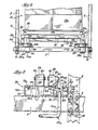
- FIGURE 2 is a front elevation view of the storage bay of Figure 1 shown with the front stops and bumpers removed and with both trolleys shown in the front location;
- FIGURE 3 is an enlarged fragmentary front view of one of the track assemblies of the storage bay with parts broken away and with the upper trolley shown in the center location;
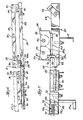
- FIGURE 4 is an enlarged plan view of the two trolleys in the locations shown in FIG. 1 with the loads removed;
- FIGURE 5 is an enlarged fragmentary plan view of the wheel assembly of the upper trolley in the position shown in FIG. 2 with the hold-down bracket removed;
- FIGURE 6 is a side elevation view of the trolleys in the locations shown in FIG. 3 on the inclined tracks; and
- FIGURE 7 is an enlarged side elevation view of the trolley track assembly and the associated catch mechanism.
- Illustrated in Fig. 1 is a storage rack assembly which includes a plurality of fore-and-
aft extending frames 2 that are formed fromvertical posts 4 rigidly interconnected by X-bracing 5 andstraight braces 6. Theframes 2 are connected by longitudinal beams or stringers 7 into a three-dimensional, stable framework or rack structure which may extend from the floor to the roof of a warehouse and provides a number of superimposed storage locations. A large number ofparallel frames 2 are used, which are uniformly spaced from one another by thestringers 7 to create a large number of vertical rows, each of which includes several superimposed storage bays 10. A single bay 10 is shown which is defined on each lateral side by a pair of alignedframes 2 that may be linked together bytie bars 11 or may be interconnected only by the tracks as described hereinafter. Each bay is capable of holding three loads of goods: one load 12a carried by anupper trolley 14 at the rear end of the bay, oneload 12b carried by alower trolley 16 at the center of the bay and one load 12c supported on atrack assembly 20 for the trolleys or upon a pair a cross supports 22 (Fig. 6) at the front location of the bay. The trolleys are movable along thetrack assembly 20 from the front of the bay rearward to allow successive loads to be supplied through the open front end of the bay which is at the lefthand edge of Fig. 1. - In accordance with the present invention, each horizontally extending storage bay 10 can store three pallet loads 12 of goods and includes an
outer track 24 and aninner track 26 extending from the front end rearward, along which the telescoped upper andlower trolleys upper trolley 14. The loaded upper trolley is moved or pushed rearward as asecond load 12b of goods is inserted and placed on thelower trolley 16. Finally, when a third load 12c is inserted through the front end of thetrack assembly 20, both loaded trolleys are pushed rearward, with theupper trolley 14 moving to a rear location in the bay and thelower trolley 16 to a central location. To empty the bay 10, the procedure is reversed. - The
track assembly 20 is inclined downward toward the front end of the bay whereby gravity causes thetrolleys track assembly 20 prevent a trolley from moving forward from the central location until released. Release means 30a, 30b (Fig. 2) upon actuation disengage theappropriate catch - The superimposed bays 10 of the storage rack assembly are generally defined by the track assemblies that are supported from the
vertical frames 2 and thehorizontal stringers 7. The width of each bay 10 is somewhat greater than the width of astandard pallet 36. Each bay has sufficient height to accommodate a loaded pallet carried upon the upper trolley and is slightly greater than 3 pallets deep. - The
trolleys Wheels 40 of the trolleys rotate onaxles 78 mounted in short verticaltubular members 39 at the four corners, and the two cornertubular members 39 on each lateral side are interconnected by lateraltubular members 38. The lateraltubular members 38 are interconnected by crosstubular pieces 41 having upper surfaces at the same level as the upper surfaces of the lateraltubular members 38, thereby defining a load-supporting surface. Loads 12 disposed onpallets 36 having their fork-entry openings facing fore-and-aft are supported on the upper surfaces of thetubular members - The
track assembly 20 includes a pair of tubular beams orrails 44 extending fore-and-aft for generally the length of the bay which rails are mounted on thehorizontal stringers 7. Upwardly open C-shaped channel sections 42, which are more than twice as wide as the rails (Fig. 3), serve a hold-down function and are placed at the front end of each rail and at a strategic central location within. The inner and outer edges of the top surfaces of therails 44 provide the inner andouter tracks wheels 40 of the lower andupper trolleys channels 42 interengage with hold-down brackets or retainers 46 carried by the trolleys to prevent derailment of the trolleys during loading or unloading of a palletized load by a fork lift or the like. - Each of the
rails 44 has rounded edges, and each of thewheels 40 has aflange 50 which extends below the upper surface and along the side of the rail and has arolling surface 52 matched to the rounded edge of the rail. Theflanges 50 of theupper trolley wheels 40 lie laterally outward with respect to the track assembly while the flanges 50' of the lower trolley wheels 40' lie inward. - The hold-down
channels 42 are placed at the positions of thewheels 40 at the front trolley location. Each C-shapedchannel 42 has alower web 53, which is disposed between the undersurface of arail 44 and one of thehorizontal stringers 7, a pair ofupstanding flanges 56 at the lateral edges thereof and a pair ofinturned edges 58. The inturned edges 58 of each channel are generally at the horizontal level of the upper surface of the rail and are spaced laterally from therail 44 providing a pair ofslots 62 along each side of the rail which accommodate thewheel flanges 50 and hold-down brackets 46. The hold-down brackets 46 depend from the lower edges of eachrectangular tube member 39 in which thewheels 40 are mounted, and each terminates in anhorizontal section 68 which is located under the correspondinginturned edge 58 ofchannel 42. The hold-down brackets 46 prevent derailment of a trolley which may inadvertently result during loading or unloading by a fork-lift truck or the like because thehorizontal sections 68 at each of the four corners of both trolleys are under theinturned flanges 58 when they are in the front location, and the possibility of the trolley wheel bounding off of the track during supply of a load which might be dropped onto eithertrolley is also eliminated. - To assure that both of the
trolleys track assembly 20 is preferably inclined downward toward the front at an angle of between about 3° and about 6°. Each of the trolleys rolls by gravity along the inclined track assembly until the trolley in the front location hits spring-loaded bumpers 74 (Fig. 5 and 7) at the front of thetrack assembly 20. Thebumpers 74 include socket-head shoulder bolts 74a which fit thru openings provided infront end brackets 75 that are welded or suitably otherwise affixed to the C-shapedchannels 42. The bolts screw into tapped holes in rectangular pads 74b, and compression springs 74c surround the bolts 74a. Two bumpers are within each of thefront channel sections 42 in flanking relationship to the front end of eachrail 44. - Although it is desirable that the trolleys roll freely to the front of the bay 10 when not restrained by the catches 28, they should not pick up excess speed in so doing lest a sudden stop, against the
bumpers 74 and back-up depending stops 77 (Fig. 7), at the front of the bay cause the goods to shift forward and possibly fall from the trolleys. Accordingly, brake means to slow down the trolleys may optionally be provided in the form ofhysteresis wheels 76 in contact with each of thetrolley wheels 40. Each of thetrolley wheels 40 is mounted on anindependent axle 78 supported from the lateral sides of therectangular tubular member 39, and an associatedhysteresis wheel 76 is mounted on anaxle 80 similarly supported in the lateral sides of thetubular member 39. Thehysteresis wheels 76 are formed of soft, resilient material, such as a soft synthetic rubber, and are mounted to press against the rolling surfaces of themetal trolley wheels 40 as they turn but mounted so as not to contact the track surface. The pressure of the hysteresis wheels is sufficient to retard the trolleys from accelerating. Alternatively, the slope of the track can be lowered slightly so the trolleys will not have a tendency to move quite as fast, and in this respect, thestringers 7 are preferably mounted upon theposts 4 with infinitely adjustable connectors 81 (Figs. 2 and 3) of the type described in U.S. Patent No. 3,877,579, issued April 15,1975 to John J. Weider, see Fig. 2. - Whereas, in the bay described in the above- mentioned U.S. Patent No. 4,155,462, the weight of a load in front of a trolley was relied upon to hold the forward-biased trolley from prematurely moving back to the front location and dumping the load thereinfront, the present invention employs a positive catch 28 to maintain a trolley in the center position until released. These positive catches assure that the trolleys will not push a load disposed in the front position into the aisle. This feature is particularly important when items of goods are picked one-by-one from the
pallets 36 in the front location rather than withdrawn only by pallet load. - A preferred catch-release mechanism, indicated generally at 82, cooperates with the hold-down brackets 46 to limit forward movement of the
trolleys 12, 14. The hold-down brackets 46a associated with thefront wheels 40 of each of the trolleys havefront edges 84 perpendicular to the lateral edges of the trolleys and have chamferedrear edges 86, whereas the hold-downbrackets 46b associated with the rear wheels have chamfered front andrear edges 86, preferably cut at an angle of 30° to 60°. One-piece elongatedcatch release rod 90 are bent upward at their back ends to form shortvertical tangs 91, which serve as the catches 28 to engage a perpendicularfront edge 84 of one of the front hold-down brackets 46a of one of thetrolleys central segment 98 of thecatch release rod 90 extends alongside therail 44. The front portion of thissegment 98 is supported in an eye 92 (Fig. 7), and the rear end of the segment of the rod adjacent thetang 91 is rotatable within anapertured bracket 94 carried at the rear of the C-shapedchannel 42. The handle 30 is bent generally perpendicularly downward from the elongatedcentral segment 98 and then to the left and forward as shown in Figs. 3 and 7. - The
release rod 90 rotates freely within theeye 92 andapertured bracket 94 and is biased in a counterclockwise direction (in reference to Fig. 3) by the weight of the release handle 30, which projects to the left toward therail 44 so that the catch 28 extends substantially vertically and is directly in the path of thehorizontal section 68 of the hold-down bracket 46. The shortperpendicular tang 91 of the catch 28 engages the perpenducularfront edge 84 of the hold-down bracket 46a associated with one of the front wheels of a trolley which prevents the trolley from moving forward until released, as shown in Figs. 3, 6 and 7. However the catches 28 do not interfere with either the rearward movement of the trolleys or the forward movement of the hold-down bracket 46b associated with therear wheels 40 because theseedges 86 of thehorizontal sections 68 are chamfered at an angle of about 30° to about 60° and push thetang 91 to the side and out of the way as the catch-release rod 90 rotates clockwise. Either trolley is manually released by turning the handle 30 to rotate the catch-release rod 91 in a clockwise direction until thetang 91 loses contact with the front hold-down bracket 46a. - The right hand catch-
release handle 30a is associated with thecatch 28a which engages the front hold-down bracket 46a of the upper trolley 14 (Fig. 6), and the lefthand catch-release handle 30b is associated with thecatch 28b which engages the front hold-down bracket 46a associated with thelower trolley 16. Although both catch-release rods 90 could be on the same side of thebay 42, it is deemed preferable to have the rods on opposite sides so as to allow the rods to be identical in construction and thus interchangeable. The catches 28 hold either theupper trolley 14 or thelower trolley 16 at the center location at least one pallet length from the front of the bay. After the load in the front location is removed, the trolley in the center location is manually released for forward travel by turning the appropriate release handle 30 clockwise. - To facilitate better understanding of the invention, a load supplying and load withdrawing sequence is now described. With the bay 10 empty and the upper and
lower trolleys pallet 36 onto the upper trolley 14 (as depicted in Fig. 2). - Thereafter, the fork lift inserts a second loaded pallet into the open front end at a level so that the
pallet 36 of thesecond load 12b engages the front edge of the upper trolley and pushes it and the first load 12a rearward to the center location generally at the middle of the bay, at which time thesecond load 12b is lowered onto thelower trolley 16. Theright hand catch 28a is deflected clockwise twice as chamfered hold-downhorizontal sections 86 move past thetang 91, which then rotates back into position and blocks the perpendicularfront edge 84 as shown in Fig. 3. - Finally, the third load 12c is inserted by the fork lift through the open front end of the bay at a level so it engages the front edge of the
lower trolley 16 and pushes it rearward which, in turn, pushes theupper trolley 14 rearward to the rear location. Wheel stops 93 at the back ends of therails 44 prevent therear trolley 14 from being pushed through the rear end of the bay. As thelower trolley 16 is pushed to the center location, the chamfered back edges of the trolley hold-downbrackets left hand catch 28b aside while passing. Therod 90b returns counterclockwise by the weight of the handle 30b until thetang 91 is in its upright position where it engages the perpendicularfront edge 84 of the front hold-down bracket 46a on thelower trolley 16 when it rolls slightly forward. The third load 12c is then lowered either directly onto therails 44 in the front location or onto a pair of cross-rails 22 installed therebetween. - When the loaded goods are needed, they are removed from the bay beginning with the third or front load 12c. Either the entire front pallet may be removed with a fork lift or items may be picked one-by-one and the pallet removed after the last item has been removed. With the
catches 28b engaged with the front hold-down bracket 46a, the lower trolley is restrained from forward motion until the release handle 30b manually rotated upward. Thus, after removal of the front load 12c, thetrolleys loads 12b and 12c forward, the release handle 30b is turned clockwise disengaging thecatch 28b from the hold-down bracket 46a of thelower trolley 16. As thelower trolley 16 and theupper trolley 14 roll forward to the front location, the chamfered front surface of thehorizontal section 68 of the rear hold-down bracket 46b pushes the associatedcatch 28b aside as it rolls past; however, theright hand catch 28a is not disturbed and halts theupper trolley 14 when the perpenducular front edge reaches it. After thesecond load 12b has been removed, theupper trolley 14 carrying the first load 12a is released for forward travel and unloading by rotating thehandle 30a clockwise. When either loaded trolley reaches the front end, its momentum is absorbed by the spring-loadedbumpers 74. - The trolley arrangement of the present invention provides for the quick visual determination of the number of loads within the bay. Two
trolleys trolley 16 at the front of the bay indicates one load in the bay. No trolleys in an empty front end of the bay or a loaded lower trolley at the front of the bay indicates twoloads 12a and 12b in the bay. No trolleys and a load 12c in the front of the bay 10 indicates a bay fully loaded with three loads. - The trolleys and the bays referred to in the description with reference to the drawings may, of course, be constructed having twice the depth so that each of the trolleys will support two palletized loads. Such a construction wherein six loads may be accommodated in each bay is feasible when reach-type fork lift trucks are employed that can extend forward to set a load upon the rear half of such a deeper trolley.
Claims (4)
Priority Applications (1)
| Application Number | Priority Date | Filing Date | Title |
|---|---|---|---|
| AT83902155T ATE26387T1 (en) | 1982-05-19 | 1983-05-18 | STORAGE LINE WITH SEVERAL STORAGE POSITIONS. |
Applications Claiming Priority (2)
| Application Number | Priority Date | Filing Date | Title |
|---|---|---|---|
| US379638 | 1982-05-19 | ||
| US06/379,638 US4462500A (en) | 1982-05-19 | 1982-05-19 | Multiple location storage bays |
Publications (3)
| Publication Number | Publication Date |
|---|---|
| EP0109440A1 EP0109440A1 (en) | 1984-05-30 |
| EP0109440A4 EP0109440A4 (en) | 1984-09-14 |
| EP0109440B1 true EP0109440B1 (en) | 1987-04-08 |
Family
ID=23498058
Family Applications (1)
| Application Number | Title | Priority Date | Filing Date |
|---|---|---|---|
| EP83902155A Expired EP0109440B1 (en) | 1982-05-19 | 1983-05-18 | Multiple location storage bays |
Country Status (4)
| Country | Link |
|---|---|
| US (1) | US4462500A (en) |
| EP (1) | EP0109440B1 (en) |
| DE (1) | DE3370753D1 (en) |
| WO (1) | WO1983003959A1 (en) |
Cited By (1)
| Publication number | Priority date | Publication date | Assignee | Title |
|---|---|---|---|---|
| WO1992014661A1 (en) * | 1991-02-15 | 1992-09-03 | The Interlake Companies, Inc. | Push-back rack |
Families Citing this family (56)
| Publication number | Priority date | Publication date | Assignee | Title |
|---|---|---|---|---|
| GB2122878B (en) * | 1982-07-02 | 1986-01-08 | Wright Scient Ltd | Racks for chromatography columns |
| US4613270A (en) * | 1983-11-17 | 1986-09-23 | Speedrack, Inc. | Storage rack having bays with multiple rails and interlocking trolleys |
| US4687404A (en) * | 1985-02-22 | 1987-08-18 | Seiz Corporation | Load transfer apparatus for push-in flow racks |
| US4715765A (en) * | 1986-04-10 | 1987-12-29 | Charles Agnoff | Gravity flow storage system |
| US4773546A (en) * | 1987-05-21 | 1988-09-27 | Konstant Products, Inc. | Pallet rack |
| US4988251A (en) * | 1987-10-21 | 1991-01-29 | Interlake, Inc. | Multiple load storage rack structure |
| US4779941A (en) * | 1988-01-21 | 1988-10-25 | Eastman Kodak Company | Track system for moving processor in and out of cabinet |
| US4955489A (en) * | 1988-08-12 | 1990-09-11 | Frazier Industrial Company | Storage rack system |
| US4915240A (en) * | 1989-02-16 | 1990-04-10 | Konstant Products, Inc. | Multiple pallet rack |
| US4949852A (en) * | 1989-09-13 | 1990-08-21 | Frazier Industrial Company | Storage rack systems |
| US4982851A (en) * | 1990-02-07 | 1991-01-08 | Konstant Anthony N | Supported pallet rack |
| US5203464A (en) * | 1990-11-05 | 1993-04-20 | Frazier Industrial Company | Storage rack systems |
| US5141118A (en) * | 1990-11-20 | 1992-08-25 | Gay Kenneth F | Multiple carriage based rack assembly |
| US5180069A (en) * | 1990-12-06 | 1993-01-19 | Advance Storage Products | Four-deep push-back warehouse storage rack system |
| US5080241A (en) * | 1991-02-08 | 1992-01-14 | Konstant Anthony N | Rolling rack for skids and the like |
| US5184738A (en) * | 1991-06-07 | 1993-02-09 | Frazier Industrial Company | Storage rack systems |
| US5178288A (en) * | 1991-11-18 | 1993-01-12 | Interroll Canada Limited | Push back pallet rack |
| US5170896A (en) * | 1992-03-16 | 1992-12-15 | Konstant Products, Inc. | Pallet return pallet rack system |
| US5348169A (en) * | 1992-07-08 | 1994-09-20 | Frazier Industrial Company | Storage rack systems |
| US5474412A (en) * | 1993-02-05 | 1995-12-12 | Pfeiffer; Harold | Flow rack system |
| CA2098433C (en) * | 1993-06-15 | 1995-04-04 | Todd Scott | Pallet storage system |
| US5415300A (en) * | 1993-11-05 | 1995-05-16 | Krummell; John V. R. | Push-back cart storage system |
| US5419444A (en) * | 1993-11-12 | 1995-05-30 | Inca Metal Products Corporation | Low profile push-back rack assembly |
| US5524776A (en) * | 1993-12-17 | 1996-06-11 | Hall; Roger W. | Low inclination push back storage rack system |
| US5476180A (en) * | 1994-05-03 | 1995-12-19 | Konstant Products, Inc. | Cart return device |
| US5482422A (en) * | 1994-08-15 | 1996-01-09 | Hammond; Theodore A. | Push back storage rack |
| US6112915A (en) * | 1995-02-14 | 2000-09-05 | Lewis; Lyman F. | Push-back storage rack |
| US5680942A (en) * | 1995-05-18 | 1997-10-28 | Metal Masters Foodservice Equipment Co., Inc. | Overhead track high density storage system with center and side guide rollers and caster lock alignment clip |
| US5597217A (en) * | 1995-05-19 | 1997-01-28 | Hoska; Gerald R. | Anti-tip bracket for high capacity shelving |
| US5848713A (en) * | 1995-10-31 | 1998-12-15 | Frazier Industrial Company | Pallet return storage system |
| US6042321A (en) * | 1996-07-30 | 2000-03-28 | Westafalia Technologies, Inc. | Automated storage and retrieval system for palletless dairy cases |
| US5964361A (en) * | 1997-02-21 | 1999-10-12 | Frazier Industrial Company | Ergonomic storage racks |
| US5944202A (en) * | 1997-11-18 | 1999-08-31 | Wylie; John F. | Material handling pushback |
| US6068141A (en) * | 1998-03-16 | 2000-05-30 | Econo-Rack Storage Equipment Limited | Push back storage rack system |
| US6129223A (en) * | 1998-05-28 | 2000-10-10 | Krummell, Jr.; John V. R. | Push-back cart storage system |
| US6112918A (en) * | 1998-10-30 | 2000-09-05 | Thomas Burgess | Product shelving construction |
| US6112917A (en) * | 1998-11-23 | 2000-09-05 | Denstor Mobile Storage Systems, Inc. | Moveable file storage supporting apparatus |
| CA2336502A1 (en) * | 2000-07-12 | 2002-01-12 | Ridg-U-Rak, Inc. | Push back storage rack system |
| US20030094124A1 (en) * | 2001-11-20 | 2003-05-22 | Wishart Andrew S. | Modular pallet display system |
| US20060231517A1 (en) * | 2003-11-17 | 2006-10-19 | Bothun Richard A | Modular storage system for logistical management of operational units |
| US7484631B2 (en) * | 2003-11-17 | 2009-02-03 | Nenger Corporation | Modular storage system for logistical management of operational units |
| US7963533B2 (en) * | 2003-11-17 | 2011-06-21 | Wenger Corporation | All-terrain retail merchandising unit |
| TWI247472B (en) * | 2004-08-27 | 2006-01-11 | Delta Electronics Inc | Stator structure |
| USD530053S1 (en) | 2004-11-17 | 2006-10-10 | Wenger Corporation | Modular storage unit |
| USD525006S1 (en) | 2004-11-17 | 2006-07-11 | Wenger Corporation | Modular storage unit |
| KR100632962B1 (en) * | 2005-04-29 | 2006-10-12 | (주)건원산업건축사사무소 | Stacked Selter System |
| US7780019B2 (en) * | 2006-06-27 | 2010-08-24 | Konstant Products, Inc. | Cantilever pallet cart |
| US7770903B2 (en) * | 2007-02-26 | 2010-08-10 | Konstant Products, Inc. | Drawer type storage cart |
| DE202008007269U1 (en) * | 2008-03-31 | 2008-08-07 | Becker Marine Systems Gmbh & Co. Kg | Pallet storage facility for the storage of stored goods, in particular for use in ships |
| US8672148B2 (en) | 2010-11-18 | 2014-03-18 | J.C.M. Industries, Inc. | Low profile push-back cart and push-back cart storage system |
| US9232856B2 (en) * | 2011-10-28 | 2016-01-12 | Spacesaver Corporation | Structural articulation joint for high density mobile carriage |
| US10106293B2 (en) | 2014-11-03 | 2018-10-23 | Fred E. Clark | Pallet for the storage and transportation of articles |
| US9999300B2 (en) | 2015-10-19 | 2018-06-19 | Frazier Industrial Company | Storage system and article retrieving method |
| EP3581522A1 (en) * | 2018-06-13 | 2019-12-18 | Logevo AB | Storage system and a pre-mounted transport supporting arrangement |
| US11478079B2 (en) | 2019-11-13 | 2022-10-25 | Pipp Mobile Storage Systems, Inc. | Mobile storage system with elevated platform |
| US12304735B2 (en) | 2020-10-07 | 2025-05-20 | Pipp Mobile Storage Systems, Inc. | Single track mobile carriage system |
Family Cites Families (9)
| Publication number | Priority date | Publication date | Assignee | Title |
|---|---|---|---|---|
| NL233908A (en) * | 1957-12-05 | |||
| US3567039A (en) * | 1967-02-07 | 1971-03-02 | George Q Evans | Elevator conveyor and storage rack system |
| US3465894A (en) * | 1968-02-15 | 1969-09-09 | John C Setecka | Portable food service device for tables and the like |
| US3945510A (en) * | 1971-08-08 | 1976-03-23 | Rack Engineering Company | Storage equipment |
| US3757967A (en) * | 1971-10-08 | 1973-09-11 | Rack Eng Co | Storage rack with dual safety bridge |
| US3895724A (en) * | 1974-03-04 | 1975-07-22 | Homer T Thompson | Gravity type drum rack with an unloading mechanism |
| GB1558141A (en) * | 1977-01-07 | 1979-12-19 | Lansing Bagnall Ltd | Storage racks for warehouses and the like |
| DE2829325C3 (en) * | 1978-07-04 | 1981-10-22 | Döring, Erich, 9442 Berneck, Sankt Gallen | High rack for panels |
| DE3035338A1 (en) * | 1980-09-19 | 1982-05-06 | Rudolf Ducke Getränke-Industrie, 2351 Trappenkamp | Storage unit for loaded pallets - has inclined roller track with pallet brake and stop for next pallet released when end pallet removed |
-
1982
- 1982-05-19 US US06/379,638 patent/US4462500A/en not_active Expired - Lifetime
-
1983
- 1983-05-18 WO PCT/US1983/000779 patent/WO1983003959A1/en not_active Ceased
- 1983-05-18 DE DE8383902155T patent/DE3370753D1/en not_active Expired
- 1983-05-18 EP EP83902155A patent/EP0109440B1/en not_active Expired
Cited By (1)
| Publication number | Priority date | Publication date | Assignee | Title |
|---|---|---|---|---|
| WO1992014661A1 (en) * | 1991-02-15 | 1992-09-03 | The Interlake Companies, Inc. | Push-back rack |
Also Published As
| Publication number | Publication date |
|---|---|
| US4462500A (en) | 1984-07-31 |
| EP0109440A1 (en) | 1984-05-30 |
| DE3370753D1 (en) | 1987-05-14 |
| EP0109440A4 (en) | 1984-09-14 |
| WO1983003959A1 (en) | 1983-11-24 |
Similar Documents
| Publication | Publication Date | Title |
|---|---|---|
| US4462500A (en) | Multiple location storage bays | |
| CA1327166C (en) | Multiple pallet rack | |
| US4982851A (en) | Supported pallet rack | |
| US4773546A (en) | Pallet rack | |
| EP0153040B1 (en) | Storage rack having bays with multiple rails and interlocking trolleys | |
| US4687404A (en) | Load transfer apparatus for push-in flow racks | |
| US4715765A (en) | Gravity flow storage system | |
| US5180069A (en) | Four-deep push-back warehouse storage rack system | |
| US4155462A (en) | Storage racks for warehouses and the like | |
| US5419444A (en) | Low profile push-back rack assembly | |
| US5328038A (en) | Storage rack systems | |
| CA2591504C (en) | Cantilever pallet cart | |
| US5170896A (en) | Pallet return pallet rack system | |
| CA2098433C (en) | Pallet storage system | |
| EP0164387B1 (en) | A storage and handling installation for palletised goods | |
| US7114904B2 (en) | Push-back pallet storage system | |
| CA2099910C (en) | Storage rack systems | |
| CA2312294C (en) | Pushback storage system | |
| CA1228056A (en) | Storage rack having load-leveling trolleys | |
| WO2005095235A1 (en) | Compact pushback storing system for pallets | |
| JP2507260B2 (en) | Fluid shelves | |
| EP0544955B1 (en) | Material handling system | |
| JPS59500861A (en) | Multi-storage compartment | |
| JPH0441307A (en) | Automatic warehouse for long-shaped material | |
| JPH0416418A (en) | Apparatus for transferring load between load receiving mount and carriage |
Legal Events
| Date | Code | Title | Description |
|---|---|---|---|
| PUAI | Public reference made under article 153(3) epc to a published international application that has entered the european phase |
Free format text: ORIGINAL CODE: 0009012 |
|
| AK | Designated contracting states |
Designated state(s): AT BE CH DE FR GB LI LU NL SE |
|
| 17P | Request for examination filed |
Effective date: 19840523 |
|
| RBV | Designated contracting states (corrected) |
Designated state(s): AT BE CH DE FR GB LI NL SE |
|
| GRAA | (expected) grant |
Free format text: ORIGINAL CODE: 0009210 |
|
| AK | Designated contracting states |
Kind code of ref document: B1 Designated state(s): AT BE CH DE FR GB LI NL SE |
|
| REF | Corresponds to: |
Ref document number: 26387 Country of ref document: AT Date of ref document: 19870415 Kind code of ref document: T |
|
| REF | Corresponds to: |
Ref document number: 3370753 Country of ref document: DE Date of ref document: 19870514 |
|
| ET | Fr: translation filed | ||
| PGFP | Annual fee paid to national office [announced via postgrant information from national office to epo] |
Ref country code: NL Payment date: 19870531 Year of fee payment: 5 |
|
| PLBE | No opposition filed within time limit |
Free format text: ORIGINAL CODE: 0009261 |
|
| STAA | Information on the status of an ep patent application or granted ep patent |
Free format text: STATUS: NO OPPOSITION FILED WITHIN TIME LIMIT |
|
| 26N | No opposition filed | ||
| PG25 | Lapsed in a contracting state [announced via postgrant information from national office to epo] |
Ref country code: GB Effective date: 19880518 Ref country code: AT Effective date: 19880518 |
|
| PG25 | Lapsed in a contracting state [announced via postgrant information from national office to epo] |
Ref country code: SE Effective date: 19880519 |
|
| PG25 | Lapsed in a contracting state [announced via postgrant information from national office to epo] |
Ref country code: LI Effective date: 19880531 Ref country code: CH Effective date: 19880531 |
|
| BERE | Be: lapsed |
Owner name: SPEEDRACK INC. Effective date: 19880531 |
|
| PG25 | Lapsed in a contracting state [announced via postgrant information from national office to epo] |
Ref country code: NL Effective date: 19881201 |
|
| NLV4 | Nl: lapsed or anulled due to non-payment of the annual fee | ||
| PG25 | Lapsed in a contracting state [announced via postgrant information from national office to epo] |
Ref country code: FR Free format text: LAPSE BECAUSE OF NON-PAYMENT OF DUE FEES Effective date: 19890131 |
|
| REG | Reference to a national code |
Ref country code: CH Ref legal event code: PL |
|
| GBPC | Gb: european patent ceased through non-payment of renewal fee | ||
| PG25 | Lapsed in a contracting state [announced via postgrant information from national office to epo] |
Ref country code: DE Effective date: 19890201 |
|
| REG | Reference to a national code |
Ref country code: FR Ref legal event code: ST |
|
| PG25 | Lapsed in a contracting state [announced via postgrant information from national office to epo] |
Ref country code: BE Effective date: 19890531 |
|
| EUG | Se: european patent has lapsed |
Ref document number: 83902155.7 Effective date: 19890518 |