EP0108795B1 - Oil distribution system for a compressor - Google Patents
Oil distribution system for a compressor Download PDFInfo
- Publication number
- EP0108795B1 EP0108795B1 EP19830901998 EP83901998A EP0108795B1 EP 0108795 B1 EP0108795 B1 EP 0108795B1 EP 19830901998 EP19830901998 EP 19830901998 EP 83901998 A EP83901998 A EP 83901998A EP 0108795 B1 EP0108795 B1 EP 0108795B1
- Authority
- EP
- European Patent Office
- Prior art keywords
- crankshaft
- cylinder head
- lubricant
- oil
- disposed
- Prior art date
- Legal status (The legal status is an assumption and is not a legal conclusion. Google has not performed a legal analysis and makes no representation as to the accuracy of the status listed.)
- Expired
Links
- 238000009826 distribution Methods 0.000 title claims description 4
- 239000000314 lubricant Substances 0.000 claims abstract description 17
- 238000005086 pumping Methods 0.000 claims description 3
- 238000004891 communication Methods 0.000 claims description 2
- 239000003507 refrigerant Substances 0.000 abstract description 5
- 238000005057 refrigeration Methods 0.000 abstract description 4
- 238000001816 cooling Methods 0.000 description 11
- OKTJSMMVPCPJKN-UHFFFAOYSA-N Carbon Chemical compound [C] OKTJSMMVPCPJKN-UHFFFAOYSA-N 0.000 description 4
- 238000009825 accumulation Methods 0.000 description 4
- 229910052799 carbon Inorganic materials 0.000 description 4
- 239000007921 spray Substances 0.000 description 4
- 230000006835 compression Effects 0.000 description 3
- 238000007906 compression Methods 0.000 description 3
- 238000009413 insulation Methods 0.000 description 2
- 230000001050 lubricating effect Effects 0.000 description 2
- 238000004519 manufacturing process Methods 0.000 description 2
- 210000000707 wrist Anatomy 0.000 description 2
- 238000003287 bathing Methods 0.000 description 1
- 230000002950 deficient Effects 0.000 description 1
- 239000000463 material Substances 0.000 description 1
- 238000000034 method Methods 0.000 description 1
- 230000002028 premature Effects 0.000 description 1
- 230000005855 radiation Effects 0.000 description 1
- 238000004804 winding Methods 0.000 description 1
Images
Classifications
-
- F—MECHANICAL ENGINEERING; LIGHTING; HEATING; WEAPONS; BLASTING
- F04—POSITIVE - DISPLACEMENT MACHINES FOR LIQUIDS; PUMPS FOR LIQUIDS OR ELASTIC FLUIDS
- F04B—POSITIVE-DISPLACEMENT MACHINES FOR LIQUIDS; PUMPS
- F04B39/00—Component parts, details, or accessories, of pumps or pumping systems specially adapted for elastic fluids, not otherwise provided for in, or of interest apart from, groups F04B25/00 - F04B37/00
- F04B39/02—Lubrication
- F04B39/0223—Lubrication characterised by the compressor type
- F04B39/023—Hermetic compressors
- F04B39/0269—Hermetic compressors with device for spraying lubricant or with mist lubrication
Definitions
- This invention relates to hermetically sealed refrigeration compressors, and more particularly to an oil distribution system for such compressors adapted to conduct heat energy from the cylinder heads within the compressor housings.
- the cooling of the cylinder head is left to the suction inlet refrigerant that is delivered directly into the compressor housing.
- refrigerant that is delivered directly into the compressor housing.
- US-A-2198258 similarly discloses cooling the cylinder head of a compressor by passing oil over it, the oil being dripped from stationary parts onto the cylinder head to provide the cooling.
- oil is sprayed against the wall of the housing and the outside of the stator body so that the oil runs down the side walls and is cooled by contact therewith.
- the location of the cylinder head is such that oil sprayed outwardly cannot reach the cylinder head itself.
- One technique for maintaining the discharge valve temperature low enough to prevent an accumulation of carbon deposits is to transfer heat energy from the cylinder head expeditiously. This invention accomplishes such heat transfer by bathing the cylinder head with a flow of oil.
- a compressor including a hermetically sealed housing having a crankcase therein with a cylinder disposed on the crankcase and a sump in a bottom portion thereof; substantially vertically disposed crankshaft rotatably received in the crankcase and having a piston operably connected thereto and disposed in the cylinder; a cylinder head the crankshaft having pump means connected to its bottom portion and disposed in the sump for pumping lubricant from the sump upwardly through a lubricant passage in the crankshaft, and a lubricant distribution system having:
- the present invention provides significant additional cooling to the cylinder, and particularly to the cylinder head, of a refrigeration compressor, thereby increasing the compressor's efficiency, preventing the premature accumulation of carbon deposits on valve arrangements, and increasing the useful life of bearings, insulation and the like.
- conventional compressor 8 comprises a lower housing 10 and upper housing 12, which may be welded or brazed at seam 14.
- crankcase 16 mounted within compressor 8 is crankcase 16 having crankshaft 18 rotatably received therethrough, and a motor 20 comprising rotor 22 secured to crankshaft 18 and stator 24 with field windings 26.
- crankshaft 18 has closed- loop end 28 of connecting rod 30 connected thereto and which has its opposite end connected by wrist pin 32 and spring clip 34 to piston 36 disposed in cylinder 38 of crankcase 16.
- Cylinder 38 has connected thereto gasket 40, leaf 42, valve plate 44, gasket 46, and cylinder head 48 by four bolts 50.
- the piston-cylinder arrangement is dynamically balanced by counterweight 52 connected to crankshaft 18.
- crankshaft 18 Disposed in lower housing 10, along with refrigerant tubing 54, is oil pump 56 which is connected to the bottom end portion of crankshaft 18 in oil sump 58.
- Crankshaft 18 has axially disposed therein oil passage 60 and upper oil passage 62 for delivering oil to lubricate typical points, such as main bearing 64 and thrust bearing 66.
- compressor 8 During operation, very high temperatures exist within compressor 8 causing the components therein, for example, motor 20, crankcase main bearing 64, crankshaft bearing 66, and most particularly cylinder head 48 to become extremely hot, thereby requiring cooling.
- oil pump 56 pumping oil from oil sump 58 upwardly through oil passage 60 to not only lubricate points, such as crankcase main bearing 64 and crankshaft bearing 66, but also to conduct heat energy from motor 20, crankcase main bearing 64, crankshaft bearing 66, and. other parts connected or in close proximity to crankshaft 18.
- oil pump 56 pumping oil from oil sump 58 upwardly through oil passage 60 to not only lubricate points, such as crankcase main bearing 64 and crankshaft bearing 66, but also to conduct heat energy from motor 20, crankcase main bearing 64, crankshaft bearing 66, and. other parts connected or in close proximity to crankshaft 18.
- oil slinger tube 68 which is fitted in opening 63 of upper oil passage 62 in the top end of crankshaft 18.
- slinger 68 is angularly disposed relative to the rotational axis of crankshaft 18.
- Slinger 68 is of a predetermined length for reasons which will be discussed below and has opening 70 disposed therein, which, as measured from the rotational axis of crankshaft 18, has an effective radius longer than the effective radius of crankshaft 18.
- slinger 68 is made of a rigid material that allows it to be angularly oriented from the vertical to direct the spray of oil away from top surface 75 and toward side surfaces 73 of upper housing 12. Furthermore, should certain compressor parts be disposed above the top end of crankshaft 18, as illustrated in Fig. 1, slinger 68 may be manufactured having a predetermined length which will insure opening 70 being above such parts, thereby preventing the existence of any obstruction in the path of the oil being slung by slinger 68.
- slinger 68 due to its angular orientation relative to the rotational axis of crankshaft 18 and the increased effective radius of opening 70, is able to sling the oil against the surfaces 73 of upper housing 12.
- slinger 68 is bent to allow directional control of the spray path of the oil exiting opening 70 for various compressor models.
- cylinder head 48 experiences extremely high temperatures during the operation of compressor 8. This is primarily due to the temperature existing within the interior space of compressor 8 and the high temperatures produced within cylinder 38 upon compression of gaseous refrigerant.
- Conventional means to alleviate the extremely high temperatures experienced by cylinder head 48 include disposing a plurality of fins 78 on cylinder head 48 to conduct the heat energy therefrom to the interior space of compressor 8. In spite of this, cylinder head 48 may still remain at undesirable temperatures during the operation of compressor 8.
- bleed holes 80 and 81 are disposed in the side of oil slinger tube 68, with bleed hole 80 facing radially outwardly therefrom. Because slinger 68 rotates with crankshaft 18, bleed hole 80 will always rotate facing towards upper housing 12. This permits a portion of the oil traveling upwardly through slinger 68 to be slung generally horizontally, radially outwardly through bleed hole 80. As slinger 68 rotates past cylinder head 48, a spray of oil is slung from bleed hole 80 onto cylinder head for cooling purposes. Little oil is slung from hole 81 since it faces radially inwardly towards the rotational axis of crankshaft 18. Hole 81 is present only because of manufacturing expediency.
- a deflector and heat sink 82 having slots 84 disposed therein is transversely disposed on the top surface of cylinder head 48. Consequently, upon slinger 68 rotating past cylinder head 48 a portion of oil is caught by deflector 82 and caused to flow over the surfaces of cylinder head 48 adjacent valve plate 44, while at the same time allowing a remaining portion of the oil to pass through slots 84 and to flow over end portion 49 of cylinder head 48 and ribs 78.
- deflector 82 is transversely disposed on the top surface portion of cylinder head 48 adjacent gasket 46.
- Deflector 82 could be disposed on the top surface of cylinder head 48 adjacent end portion 49, however, due to the small confines generally existing between cylinder head 48 and upper housing 12, it has been found that deflector 82 performs its desired function most efficiently when disposed adjacent gasket 46.
- deflector 82 is of a predetermined height and desirably disposed away from housing 10 to allow for production tolerances.
Landscapes
- Engineering & Computer Science (AREA)
- Mechanical Engineering (AREA)
- General Engineering & Computer Science (AREA)
- Compressor (AREA)
Abstract
Description
- This invention relates to hermetically sealed refrigeration compressors, and more particularly to an oil distribution system for such compressors adapted to conduct heat energy from the cylinder heads within the compressor housings.
- In those refrigeration compressors utilizing a piston-cylinder arrangement for compression, the gaseous refrigerant becomes extremely hot upon compression and conducts heat energy to the cylinder and cylinder head, thereby increasing temperatures of the cylinder and cylinder head. These higher temperatures may cause lubricant to boil and lose its lubricating properties, which eventually results in carbon deposits forming on valves, valve seats, leaf plates and the like. The steady accumulation of such deposits will eventually destroy the integrity of the valve arrangement requiring shutdown of the compressor and replacement of the defective parts.
- Generally, the cooling of the cylinder head is left to the suction inlet refrigerant that is delivered directly into the compressor housing. Although adequate to acceptably cool the cylinder head, higher compressor efficiencies are obtainable if the cylinder head is cooled even further.
- The most relevant prior art of which applicants are aware is U.S. Patent No. 2,125,645 issued to Money on August 2,1938. Money has a short tube extending upwardly from the top opening of the oil passage in the crankshaft that serves to spray oil upon the top surfaces of compressor components. To insure that some of the oil will fall upon the outer surfaces of the pistons and cylinder to lubricate them, a baffle is connected to the top of the cylinder to deflect some of the sprayed oil so that it may drip downwardly onto the outer surfaces of the piston. It appears that the majority of the oil which is sprayed over the baffle impacts the compressor housing to return to the oil sump in the bottom of the compressor. It should be noted that the baffle in the Money patent is disposed on the most axially inwardly portion of the cylinder to insure deflection of oil to lubricate the piston.
- US-A-2198258 similarly discloses cooling the cylinder head of a compressor by passing oil over it, the oil being dripped from stationary parts onto the cylinder head to provide the cooling. In US-A-2628016 oil is sprayed against the wall of the housing and the outside of the stator body so that the oil runs down the side walls and is cooled by contact therewith. There is no teaching in the specification of the cooling of the cylinder head by the oil and further it is noted that the location of the cylinder head is such that oil sprayed outwardly cannot reach the cylinder head itself.
- Other devices have been used to decrease the extremely high temperatures of the cylinder head, for example, heat radiation fins disposed on the cylinder head, which have been effective in various degrees in lowering the cylinder head temperature. However, further cylinder head temperature reduction is desirable in order to increase compressor efficiency, prevent accumulation of carbon deposits on the valve arrangements, and prolong the life of parts such as bearings, insulation and the like.
- One technique for maintaining the discharge valve temperature low enough to prevent an accumulation of carbon deposits is to transfer heat energy from the cylinder head expeditiously. This invention accomplishes such heat transfer by bathing the cylinder head with a flow of oil.
- According to the present invention there is provided a compressor including a hermetically sealed housing having a crankcase therein with a cylinder disposed on the crankcase and a sump in a bottom portion thereof; substantially vertically disposed crankshaft rotatably received in the crankcase and having a piston operably connected thereto and disposed in the cylinder; a cylinder head the crankshaft having pump means connected to its bottom portion and disposed in the sump for pumping lubricant from the sump upwardly through a lubricant passage in the crankshaft, and a lubricant distribution system having:
- a generally elongate hollow body connected to the crankshaft and in communication with the lubricant passage and having an opening through which lubricant is thrown radially outwardly upon rotation of the crankshaft, characterized by
- means substantially vertically upstanding from the cylinder head for directing a portion of the lubricant slung by the generally elongate hollow body to said cylinder head to conduct heat energy therefrom.
- Upon rotation of the crankshaft, a portion of the oil pumped upwardly through the elongate body is slung generally radially outwardly through the opening in the side of the body, and, upon reaching the transversely disposed oil deflector on the cylinder head, deflected by the oil deflector to flow over the side and end exterior surfaces of the cylinder head to conduct heat therefrom.
- The present invention provides significant additional cooling to the cylinder, and particularly to the cylinder head, of a refrigeration compressor, thereby increasing the compressor's efficiency, preventing the premature accumulation of carbon deposits on valve arrangements, and increasing the useful life of bearings, insulation and the like.
- The above mentioned and other features and objects of this invention, and the manner of obtaining them will become more apparent and the invention itself will be better understood by reference to the following description of an embodiment of the invention taken in conjunction with the accompanying drawings, wherein:
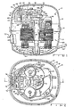
- Figure 1 is a sectional view of Fig. 2 along the line 1-1 and viewed in the direction of the arrows;
- Figure 2 is a broken-away top plan view of Fig. 1;
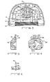
- Figure 3 is a broken-away, elevational view of the upper portion of a compressor viewed from the left side of Fig. 1;
- Figure 4 is an internal view of the cylinder head of the compressor;
- Figure 5 is a sectional view of Fig. 4 along line 5-5 as viewed in the direction of the arrows; and
- Fig. 6 is a side elevational view of an oil tube disposed in the oil passage of a crankshaft.
- Referring to the drawings, and particularly Fig. 1,
conventional compressor 8 comprises alower housing 10 andupper housing 12, which may be welded or brazed atseam 14. Mounted withincompressor 8 iscrankcase 16 havingcrankshaft 18 rotatably received therethrough, and amotor 20 comprisingrotor 22 secured tocrankshaft 18 andstator 24 withfield windings 26. - The upper portion of
crankshaft 18 has closed-loop end 28 of connectingrod 30 connected thereto and which has its opposite end connected bywrist pin 32 andspring clip 34 to piston 36 disposed incylinder 38 ofcrankcase 16.Cylinder 38 has connected theretogasket 40,leaf 42,valve plate 44,gasket 46, andcylinder head 48 by fourbolts 50. The piston-cylinder arrangement is dynamically balanced bycounterweight 52 connected tocrankshaft 18. - Disposed in
lower housing 10, along withrefrigerant tubing 54, isoil pump 56 which is connected to the bottom end portion ofcrankshaft 18 inoil sump 58.Crankshaft 18 has axially disposed thereinoil passage 60 and upper oil passage 62 for delivering oil to lubricate typical points, such as main bearing 64 and thrust bearing 66. - During operation, very high temperatures exist within
compressor 8 causing the components therein, for example,motor 20, crankcase main bearing 64, crankshaft bearing 66, and most particularlycylinder head 48 to become extremely hot, thereby requiring cooling. - Generally, the cooling of the above mentioned parts is accomplished by
oil pump 56 pumping oil fromoil sump 58 upwardly throughoil passage 60 to not only lubricate points, such as crankcase main bearing 64 and crankshaft bearing 66, but also to conduct heat energy frommotor 20, crankcase main bearing 64, crankshaft bearing 66, and. other parts connected or in close proximity tocrankshaft 18. Upon termination of its upward travel throughoil passage 60 or upper oil passage 62, the oil is returned tooil sump 58 at very high temperatures, and, if not properly cooled, may prematurely lose its lubricating properties, thereby possibly resulting in the early failure of wrist pin, bearings and the like. - A unique means of cooling the oil is provided by
oil slinger tube 68, which is fitted in opening 63 of upper oil passage 62 in the top end ofcrankshaft 18. In the present embodiment,slinger 68 is angularly disposed relative to the rotational axis ofcrankshaft 18.Slinger 68 is of a predetermined length for reasons which will be discussed below and has opening 70 disposed therein, which, as measured from the rotational axis ofcrankshaft 18, has an effective radius longer than the effective radius ofcrankshaft 18. - The cooling of the oil takes place upon
motor 20 being energized through conventionalmulti-pin terminal 72, which causesrotor 22 to rotatecrankshaft 18 andoil pump 56. As the oil is pumped upwardly byoil pump 56 throughoil passage 60 and upper oil passage 62, a portion of the oil will be urged upwardly throughslinger 68 and opening 70 to be slung generally upwardly and radially outwardly againstside surfaces 73 ofupper housing 12. Because bothlower housing 10 andupper housing 12 are cooler than the oil, heat energy will be conducted from the oil tohousings oil sump 58. To insure the oil being slung byslinger 68 does not impacttop surfaces 75 ofupper housing 12, and consequently drip downwardly upon compressor parts, such asdischarge muffler cover 74,suction muffler cover 76, and the other above mentioned parts,slinger 68 is made of a rigid material that allows it to be angularly oriented from the vertical to direct the spray of oil away fromtop surface 75 and towardside surfaces 73 ofupper housing 12. Furthermore, should certain compressor parts be disposed above the top end ofcrankshaft 18, as illustrated in Fig. 1,slinger 68 may be manufactured having a predetermined length which will insure opening 70 being above such parts, thereby preventing the existence of any obstruction in the path of the oil being slung byslinger 68. - To reiterate, slinger 68, due to its angular orientation relative to the rotational axis of
crankshaft 18 and the increased effective radius of opening 70, is able to sling the oil against thesurfaces 73 ofupper housing 12. In addition,slinger 68 is bent to allow directional control of the spray path of the oil exiting opening 70 for various compressor models. - It was earlier mentioned that
cylinder head 48 experiences extremely high temperatures during the operation ofcompressor 8. This is primarily due to the temperature existing within the interior space ofcompressor 8 and the high temperatures produced withincylinder 38 upon compression of gaseous refrigerant. Conventional means to alleviate the extremely high temperatures experienced bycylinder head 48 include disposing a plurality offins 78 oncylinder head 48 to conduct the heat energy therefrom to the interior space ofcompressor 8. In spite of this,cylinder head 48 may still remain at undesirable temperatures during the operation ofcompressor 8. - To reduce the temperature of
cylinder head 48, bleedholes oil slinger tube 68, withbleed hole 80 facing radially outwardly therefrom. Because slinger 68 rotates withcrankshaft 18,bleed hole 80 will always rotate facing towardsupper housing 12. This permits a portion of the oil traveling upwardly throughslinger 68 to be slung generally horizontally, radially outwardly throughbleed hole 80. Asslinger 68 rotatespast cylinder head 48, a spray of oil is slung from bleedhole 80 onto cylinder head for cooling purposes. Little oil is slung fromhole 81 since it faces radially inwardly towards the rotational axis ofcrankshaft 18. Hole 81 is present only because of manufacturing expediency. - To insure that a portion of the oil slung from
bleed hole 80 flows overend portion 49 ofcylinder head 48 andribs 78 disposed thereon, a deflector andheat sink 82 havingslots 84 disposed therein is transversely disposed on the top surface ofcylinder head 48. Consequently, uponslinger 68 rotating past cylinder head 48 a portion of oil is caught bydeflector 82 and caused to flow over the surfaces ofcylinder head 48adjacent valve plate 44, while at the same time allowing a remaining portion of the oil to pass throughslots 84 and to flow overend portion 49 ofcylinder head 48 andribs 78. - As illustrated in Figs. 1 and 5,
deflector 82 is transversely disposed on the top surface portion ofcylinder head 48adjacent gasket 46.Deflector 82 could be disposed on the top surface ofcylinder head 48adjacent end portion 49, however, due to the small confines generally existing betweencylinder head 48 andupper housing 12, it has been found thatdeflector 82 performs its desired function most efficiently when disposedadjacent gasket 46. Furthermore,deflector 82 is of a predetermined height and desirably disposed away fromhousing 10 to allow for production tolerances.
Claims (6)
Priority Applications (1)
| Application Number | Priority Date | Filing Date | Title |
|---|---|---|---|
| AT83901998T ATE28921T1 (en) | 1982-05-03 | 1983-05-03 | OIL DISTRIBUTION SYSTEM FOR A COMPRESSOR. |
Applications Claiming Priority (2)
| Application Number | Priority Date | Filing Date | Title |
|---|---|---|---|
| US37408782A | 1982-05-03 | 1982-05-03 | |
| US374087 | 1982-05-03 |
Publications (4)
| Publication Number | Publication Date |
|---|---|
| EP0108795A1 EP0108795A1 (en) | 1984-05-23 |
| EP0108795A4 EP0108795A4 (en) | 1984-09-06 |
| EP0108795B1 true EP0108795B1 (en) | 1987-08-12 |
| EP0108795B2 EP0108795B2 (en) | 1990-09-12 |
Family
ID=23475226
Family Applications (1)
| Application Number | Title | Priority Date | Filing Date |
|---|---|---|---|
| EP19830901998 Expired EP0108795B2 (en) | 1982-05-03 | 1983-05-03 | Oil distribution system for a compressor |
Country Status (7)
| Country | Link |
|---|---|
| EP (1) | EP0108795B2 (en) |
| AU (1) | AU548855B2 (en) |
| DE (1) | DE3373009D1 (en) |
| DK (1) | DK156966C (en) |
| IN (1) | IN161030B (en) |
| SU (1) | SU1521286A3 (en) |
| WO (1) | WO1983003878A1 (en) |
Families Citing this family (2)
| Publication number | Priority date | Publication date | Assignee | Title |
|---|---|---|---|---|
| RU2211370C1 (en) * | 2002-04-17 | 2003-08-27 | Барановичский станкостроительный завод ЗАО "Атлант" | Hermetically sealed refrigerant compressor |
| CN112049775A (en) * | 2020-09-16 | 2020-12-08 | 江西红海力能源科技有限公司 | Compressor that noise cancelling effect is good |
Family Cites Families (12)
| Publication number | Priority date | Publication date | Assignee | Title |
|---|---|---|---|---|
| US2050385A (en) * | 1935-05-25 | 1936-08-11 | Westinghouse Electric & Mfg Co | Blower |
| US2125645A (en) * | 1936-06-11 | 1938-08-02 | Crosley Radio Corp | Lubricating enclosed engines |
| US2198258A (en) | 1937-01-21 | 1940-04-23 | Crosley Corp | Refrigeration system |
| FR871115A (en) * | 1941-03-28 | 1942-04-09 | Advanced "hermetic" motor-compressor unit for refrigeration equipment | |
| US2504528A (en) * | 1944-09-06 | 1950-04-18 | Philco Corp | Refrigeration apparatus |
| GB576016A (en) * | 1944-09-26 | 1946-03-14 | Standard Pressed Steel Co | An improved method of lubricating refrigerator compressors and the like |
| US2628016A (en) * | 1946-03-05 | 1953-02-10 | Tecumseh Products Co | Refrigerating apparatus |
| US2500751A (en) * | 1947-05-19 | 1950-03-14 | Westinghouse Electric Corp | Refrigeration apparatus |
| DE938313C (en) * | 1952-12-13 | 1956-01-26 | Teves Kg Alfred | Motor compressors |
| US3285504A (en) * | 1964-12-10 | 1966-11-15 | Gen Motors Corp | Refrigerant apparatus |
| DE1551285A1 (en) * | 1967-05-17 | 1970-04-16 | Giovanni Borghi | Encapsulated motor-compressor unit with ribbed cylinder for cooling circuits |
| US3451615A (en) * | 1967-07-12 | 1969-06-24 | Tecumseh Products Co | Compressor lubricating system |
-
1983
- 1983-05-03 WO PCT/US1983/000660 patent/WO1983003878A1/en not_active Ceased
- 1983-05-03 AU AU16057/83A patent/AU548855B2/en not_active Ceased
- 1983-05-03 DE DE8383901998T patent/DE3373009D1/en not_active Expired
- 1983-05-03 EP EP19830901998 patent/EP0108795B2/en not_active Expired
- 1983-06-28 IN IN801/CAL/83A patent/IN161030B/en unknown
- 1983-12-16 DK DK581683A patent/DK156966C/en not_active IP Right Cessation
-
1984
- 1984-01-02 SU SU843694950A patent/SU1521286A3/en active
Also Published As
| Publication number | Publication date |
|---|---|
| WO1983003878A1 (en) | 1983-11-10 |
| SU1521286A3 (en) | 1989-11-07 |
| EP0108795A1 (en) | 1984-05-23 |
| DK581683D0 (en) | 1983-12-16 |
| DE3373009D1 (en) | 1987-09-17 |
| DK156966C (en) | 1990-03-19 |
| EP0108795B2 (en) | 1990-09-12 |
| EP0108795A4 (en) | 1984-09-06 |
| DK581683A (en) | 1983-12-16 |
| AU548855B2 (en) | 1986-01-02 |
| IN161030B (en) | 1987-09-19 |
| DK156966B (en) | 1989-10-23 |
| AU1605783A (en) | 1983-11-21 |
Similar Documents
| Publication | Publication Date | Title |
|---|---|---|
| US4569639A (en) | Oil distribution system for a compressor | |
| CA1246507A (en) | Oil dispersing device | |
| US5087170A (en) | Rotary compressor | |
| US6155805A (en) | Hermetic compressor having acoustic insulator | |
| US2113691A (en) | Compressor | |
| US4518330A (en) | Rotary compressor with heat exchanger | |
| KR100857964B1 (en) | Hermetic compressor | |
| US4928651A (en) | Integral engine block air cooled engine oil cooler | |
| US5888055A (en) | Connection between a refrigerant pipe and a suction muffler of a hermetic reciprocating compressor | |
| CN1016259B (en) | Scroll compressor | |
| JP7791909B2 (en) | Low-pressure chamber rotary compressor and air conditioner | |
| CA1216832A (en) | Oil cooled, hermetic refrigerant compressor | |
| JP2011528076A (en) | Refrigeration compressor with internal cooling system | |
| EP0108795B2 (en) | Oil distribution system for a compressor | |
| EP0107728B1 (en) | Compressor unit with an oil slinger device | |
| US3295753A (en) | Refrigerating apparatus | |
| US6688432B2 (en) | Piston compressor | |
| CA1231925A (en) | Oil distribution system for a compressor | |
| US3187994A (en) | Hermetically sealed motor compressors particularly suitable for small refrigerating machines | |
| EP0105127B1 (en) | Rotary compressor | |
| CN119123696B (en) | Gas-liquid separators and compression equipment | |
| US5271247A (en) | Cooling device for a hermetic motor-driven compressor | |
| JPS59500780A (en) | Lubricant distribution device for compressor | |
| KR930007671Y1 (en) | Cooling of compressor | |
| GB2070150A (en) | Sealed motor-compressor unit for a refrigerator |
Legal Events
| Date | Code | Title | Description |
|---|---|---|---|
| PUAI | Public reference made under article 153(3) epc to a published international application that has entered the european phase |
Free format text: ORIGINAL CODE: 0009012 |
|
| 17P | Request for examination filed |
Effective date: 19840118 |
|
| AK | Designated contracting states |
Designated state(s): AT BE CH DE FR GB LI LU NL SE |
|
| GRAA | (expected) grant |
Free format text: ORIGINAL CODE: 0009210 |
|
| AK | Designated contracting states |
Kind code of ref document: B1 Designated state(s): AT BE CH DE FR GB LI LU NL SE |
|
| PG25 | Lapsed in a contracting state [announced via postgrant information from national office to epo] |
Ref country code: NL Effective date: 19870812 Ref country code: LI Effective date: 19870812 Ref country code: CH Effective date: 19870812 Ref country code: BE Effective date: 19870812 Ref country code: AT Effective date: 19870812 |
|
| REF | Corresponds to: |
Ref document number: 28921 Country of ref document: AT Date of ref document: 19870815 Kind code of ref document: T |
|
| PG25 | Lapsed in a contracting state [announced via postgrant information from national office to epo] |
Ref country code: SE Effective date: 19870831 |
|
| ET | Fr: translation filed | ||
| REF | Corresponds to: |
Ref document number: 3373009 Country of ref document: DE Date of ref document: 19870917 |
|
| REG | Reference to a national code |
Ref country code: CH Ref legal event code: PL |
|
| NLV1 | Nl: lapsed or annulled due to failure to fulfill the requirements of art. 29p and 29m of the patents act | ||
| PLBI | Opposition filed |
Free format text: ORIGINAL CODE: 0009260 |
|
| PG25 | Lapsed in a contracting state [announced via postgrant information from national office to epo] |
Ref country code: LU Free format text: LAPSE BECAUSE OF NON-PAYMENT OF DUE FEES Effective date: 19880531 |
|
| 26 | Opposition filed |
Opponent name: DANFOSS A/S Effective date: 19880510 |
|
| PGFP | Annual fee paid to national office [announced via postgrant information from national office to epo] |
Ref country code: GB Payment date: 19900420 Year of fee payment: 8 |
|
| PUAH | Patent maintained in amended form |
Free format text: ORIGINAL CODE: 0009272 |
|
| STAA | Information on the status of an ep patent application or granted ep patent |
Free format text: STATUS: PATENT MAINTAINED AS AMENDED |
|
| 27A | Patent maintained in amended form |
Effective date: 19900912 |
|
| AK | Designated contracting states |
Kind code of ref document: B2 Designated state(s): AT BE CH DE FR GB LI LU NL SE |
|
| ET3 | Fr: translation filed ** decision concerning opposition | ||
| PG25 | Lapsed in a contracting state [announced via postgrant information from national office to epo] |
Ref country code: GB Effective date: 19910503 |
|
| GBPC | Gb: european patent ceased through non-payment of renewal fee | ||
| PGFP | Annual fee paid to national office [announced via postgrant information from national office to epo] |
Ref country code: DE Payment date: 19960418 Year of fee payment: 14 |
|
| PG25 | Lapsed in a contracting state [announced via postgrant information from national office to epo] |
Ref country code: DE Free format text: LAPSE BECAUSE OF NON-PAYMENT OF DUE FEES Effective date: 19980203 |
|
| PGFP | Annual fee paid to national office [announced via postgrant information from national office to epo] |
Ref country code: FR Payment date: 20000329 Year of fee payment: 18 |
|
| PG25 | Lapsed in a contracting state [announced via postgrant information from national office to epo] |
Ref country code: FR Free format text: LAPSE BECAUSE OF NON-PAYMENT OF DUE FEES Effective date: 20020131 |