EP0106964A2 - Method and apparatus for compensating CT images for truncated projections - Google Patents
Method and apparatus for compensating CT images for truncated projections Download PDFInfo
- Publication number
- EP0106964A2 EP0106964A2 EP83108168A EP83108168A EP0106964A2 EP 0106964 A2 EP0106964 A2 EP 0106964A2 EP 83108168 A EP83108168 A EP 83108168A EP 83108168 A EP83108168 A EP 83108168A EP 0106964 A2 EP0106964 A2 EP 0106964A2
- Authority
- EP
- European Patent Office
- Prior art keywords
- projection
- projections
- truncated
- moments
- determining
- Prior art date
- Legal status (The legal status is an assumption and is not a legal conclusion. Google has not performed a legal analysis and makes no representation as to the accuracy of the status listed.)
- Granted
Links
Images

Classifications
-
- G—PHYSICS
- G06—COMPUTING OR CALCULATING; COUNTING
- G06T—IMAGE DATA PROCESSING OR GENERATION, IN GENERAL
- G06T12/00—Tomographic reconstruction from projections
- G06T12/10—Image preprocessing, e.g. calibration, positioning of sources or scatter correction
-
- A—HUMAN NECESSITIES
- A61—MEDICAL OR VETERINARY SCIENCE; HYGIENE
- A61B—DIAGNOSIS; SURGERY; IDENTIFICATION
- A61B6/00—Apparatus or devices for radiation diagnosis; Apparatus or devices for radiation diagnosis combined with radiation therapy equipment
- A61B6/52—Devices using data or image processing specially adapted for radiation diagnosis
- A61B6/5258—Devices using data or image processing specially adapted for radiation diagnosis involving detection or reduction of artifacts or noise
-
- G—PHYSICS
- G06—COMPUTING OR CALCULATING; COUNTING
- G06T—IMAGE DATA PROCESSING OR GENERATION, IN GENERAL
- G06T2211/00—Image generation
- G06T2211/40—Computed tomography
- G06T2211/432—Truncation
Definitions
- Fig. 5 illustrates two areas where the moments behave in an unexpected fashion, those areas being bracketed at 57 and 58. It is seen that in the area 57, the amplitude of the zeroeth order moment 0 0 increases in an unexpected fashion and the initially well behaved first order moment 0 1 shows an unexpected undulation. Thus, each view encompassed within the area 57 can be said to be truncated, and expected moments should be determined to compare with the actual ones for the purpose of completing the views.
- the more or less straight line segment 60 is determined to be a better estimate of what the moment of the completed data set would have been, and the straight line section 61 estimated to be a more likely first order moment for the area if the projection set had been complete. Similar criteria lead to the identification of the views bracketed at 58 as being truncated, and in the estimation of straight.line 62 as a more likely zeroeth order moment and straight line 63 as a more likely first order moment for the area had the views been complete. While it is convenient to use straight lines, other curves could be used if desired.
- step 82 determines the amount of mass which was truncated by using the zeroeth order moment information. More particularly, recalling Fig. 5, and assuming the system is operating on a view within the bracketed portion 57, the system would determine the difference between the estimated zeroeth order moment 60 and the corresponding measured moment from the truncated data.
- Equation 18 can be manipulated to yield a form more adaptable to utilizing the moment and view information in determining the coefficients of the extended function. After some manipulation, and utilizing both the zeroeth and first order moments, equation 7 leads to:
Landscapes
- Engineering & Computer Science (AREA)
- Health & Medical Sciences (AREA)
- Life Sciences & Earth Sciences (AREA)
- Medical Informatics (AREA)
- Physics & Mathematics (AREA)
- Biomedical Technology (AREA)
- Molecular Biology (AREA)
- Biophysics (AREA)
- Nuclear Medicine, Radiotherapy & Molecular Imaging (AREA)
- Optics & Photonics (AREA)
- Pathology (AREA)
- Radiology & Medical Imaging (AREA)
- Computer Vision & Pattern Recognition (AREA)
- Heart & Thoracic Surgery (AREA)
- High Energy & Nuclear Physics (AREA)
- Surgery (AREA)
- Animal Behavior & Ethology (AREA)
- General Health & Medical Sciences (AREA)
- Public Health (AREA)
- Veterinary Medicine (AREA)
- General Physics & Mathematics (AREA)
- Theoretical Computer Science (AREA)
- Apparatus For Radiation Diagnosis (AREA)
- Analysing Materials By The Use Of Radiation (AREA)
Abstract
Description
- This invention relates to computed tomography and more particularly to a method and apparatus for reducing artifacts in CT images which result from an object extending beyond the scanner's field of view.
- For a CT scanner to produce accurately reconstructed pictures it is necessary that the body being examined be confined within the scanner's field of view and that accurate reference channel data be available. The reference channels, typically adjacent to the channels that measure attenuation data, serve as monitors of the incident radiation beam intensity. The field of view is the area, typically circular, about which the source, or source and detector, rotate to expose the body and detect radiation from a plurality of angles around the body. If the body extends beyond the field of view, some of the measured projections are in error due to (a) shielding of the reference detectors thereby corrupting the reference channel information for some of the views and (b) failure to collect attenuation information concerning portions of the body extending beyond the field of view resulting in truncated views. For the former condition, the final image has low frequency shading resulting from improper reference level shifting. For the latter condition artifacts manifest themselves typically as low spatial frequency shading or cupping, and sometimes also as streaks.
- For some kinds of scans, it is simply not possible to obtain the desired slice while assuring that the body remains within the field of view. For example, when scanning the upper portion of the torso of large individuals, it may not be possible to assure that the shoulders remain within the field of view.
- In view of the foregoing, it is an aim of the present invention to minimize artifacts in images created from truncated projection sets.
- In accomplishing that aim, it is an object of the present invention to identify projections having faulty reference information, and to improve that reference information before normalization.
- A further object of the invention is to identify truncated projection sets and complete those sets with best estimate information derived from non-truncated sets. Finally, an object of the present invention is to accomplish the foregoing in an efficient manner which does not unacceptably increase the time needed to produce the CT image.
- Other objects and advantages will become apparent from the following detailed description when taken in conjunction with the drawings, in which:
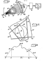
- Figure 1 is a schematic view illustrating the major elements of a CT scanner;
- Fig. 2 is a diagram illustrating an object extending beyond the field of view;
- Fig. 3 is a flowchart illustrating the manner of improving reference channel information in accordance with the present invention;
- Fig. 4 is a diagram illustrating a truncated projection set;
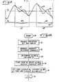
- Fig. 5 illustrates the zeroeth and first order moments for a truncated projection set; and
- Fig. 6 is a flowchart illustrating the completion of truncated projection sets in practicing the present invention.
- While the invention will be described in connection with certain preferred embodiments, there is no intent to limit it to those embodiments. On the contrary, the intent is to cover all alternatives, modifications and equivalents included within the spirit and scope of the invention as defined by the appended claims.
- Turning now to the drawings, Fig. 1 schematically illustrates the major elements of a CT scanner. Note that a "rotate-only., or .third generation" scanner is shown for purposes of illustation, although the principles of this invention are not limited to such geometry. The scanner includes a source of penetrating radiation 10, very often in the form of a rotating anode x-ray tube. The radiation produced by the x-ray tube 10 is collimated at 11 to produce a thin fan beam of
radiation 12 which is projected through apatient aperture 13 toward anx-ray detector array 14. A body to be examined, such as apatient 15, is positioned within thepatient aperture 13 in the path of the fan beam ofx-rays 12 such that the beam passing through the body is attenuated in dependence on the density of the objects encountered. As a result, each detector cell 14a, 14b, etc. produces an electrical signal which is dependent on the intensity of the radiation received within the cell. The signals thus produced are therefore measures of the attentuation of the x-ray beam by the portion of the body through which it passed. - In operation, x-ray readings are taken from each cell at a plurality of angular positions with respect to the patient, as the source and detector array are rotated about the patient aperture. Each set of readings at a particular angle is often referred to as a projection or view. A typical view for one available scanner is made up of 512 individual detector readings. Those readings for each view are digitized and fed to a
reconstruction computer 16 which can use one of a number of available algorithms to produce the image of the cross section traversed by the fan beam. The image can be displayed on aCRT 17 or alternatively can be used to create a film for further study by a diagnostician. - A
circle 20 within thepatient aperture 13, and centered on the axis of rotation of the source and detector, represents the field of view for the geometry illustrated in Fig. 1. If accurate reconstructions are to be made, thepatient 15 must be confined within the field ofview 20, in order to first of all get reliable reference channel information and secondly to produce non-truncated projections. - In the illustrated embodiment, the
end detector cells 14x, 14y of the detector array are not used for determining attenuation of the patient, but instead are used to produce reference readings characteristic of the unattenuated intensity of the x-ray source. Thus, it is important that radiation represented by therays patient aperture 13, but outside thefield view 20, impinge on thecells 14x, 14y without interference. It is those readings which are used in thereconstruction computer 16 to normalize the readings from the remainder of the fan generally indicated at 23. - , Fig. 2 diagrammatically illustrates the problem. The field of
view 20 is illustrated along with a body to be examined 15 having a portion 15a within the field of view, but portions 15b, 15c extending beyond that field. A pair of projections are illustrated at 25, 26. It is seen that the projection 25 is "normal" in that thereference rays view 20 unobstructed for receipt by their associated detector cells. Similarly, theentire body 15 is scanned in that the entire body passes radiation which will be detected. - However, the
view 26 illustrates a projection which is truncated in two ways. First of all, both of thereference beams reference channels 14x, 14y will not be a true measure of the unattenuated intensity of the x-ray source for that view. Secondly, the attenuation of the entire body is not measured inview 26 because portions 15b and 15c are not within the field of view and, even if they were exposed to x-rays, those x-rays would not be detected. Thus, for theview 26, the scanner acts as if it were measuring a different body comprising only the section 15a. - The effect of the two conditions noted above can have a serious effect on the CT image if it were simply processed in the normal way. First of all, the obscuring of the reference channels for some of the projections causes each of those obscured projections to include a uniform d.c. shift. Such a d.c. shift tends to produce low frequency shading in any reconstruction made using the obscured projections. We have found that the d.c. shift caused simply by obscuring the reference channels can be on the order of 70 H.U. in typical clinical cases, a significant quantity.
- In practicing the invention, the d.c. shift of the logrithmic projections for truncated views in which the reference channels were obscured is substantially reduced by identifying each view having obscured reference channel information and replacing it with better information derived from non-truncated projections. The manner in which that is accomplished is best explained with reference to Fig. 3, which illustrates a sequence of steps carried out within the apparatus of Fig. 1.
- After starting the procedure at
step 30, the apparatus is first cycled atstep 31 to produce a projection or view for each angled as the source and detector rotate through a range of θ's around the patient. Scanners are available which can produce about 511 readings for each projection, and take approximately 576 projections as the source and detector rotate about the body Each of those projections has reference cell intensify information associated therewith, referred to as Ir in Fig. 3. Having produced all the projections atstep 31, the system cycles to astep 32 which searches through each projection for the maximum intensity among all the reference channel information. Having acquired that maximum intensity information, the system determines a threshold intensity IT which is some fraction of the maximum intensity. Each reference intensity is then compared with the threshold so that the system can make a determination as to whether the reference channel for any view was likely obscured. As noted at 34, the first view is selected and at 35 the reference channel information obtained for that view. Atstep 36, the reference channel information is compared to the threshold intensity. If the reference channel is found to be below the threshold, astep 37 is used to flag that projection for later operation. If, on the contrary, the reference channel information is above the threshold, it is concluded that the view was made with unobscured reference channels. In that event, the intensity information is stored at astep 38 and an index incremented at 39 to produce typical reference information for later use. Astep 40 is then used to select the next view and the procedure repeated. In each case, the view is either flagged at 37 or added to the summation at 38, depending on its relationship to the threshold intensity. After all views have been processed, a step 41 calculates a typical intensity, in the illustrated embodiment an average intensity, for the good views by dividing the summed intensity values by the number of values so summed. The program then atstep 42 retrieves in turn each view or projection which had been flagged atstep 37 and, for each of those views atstep 43 replaces the reference intensity information with the average information calculated in step 41. - Having accomplished that for all views, the best reference channel information is then available and a
step 44 can be accomplished to normalize each view in the conventional fashion. - We have found that processing the reference channel information in this way has proven to correct an error of about 70 H.U. by more than 50 H.U., thus proving to be of worthwhile benefit. A large part of the remaining error is due to the second type of aberration discussed above, namely, the presence of views in which portions of the body did not contribute to the projection set. That aspect of the problem can best be illustrated with reference to Fig. 4.
- Fig. 4 represents a plot of the measured logarithmic attenuation values for a view or projection. The amplitude is plotted along the vertical axis, and detector position within the fan is plotted as φ along the horizontal axis. The central detector is illustrated in the center of the array at φ = 0. The plot is intended to illustrate a truncated view in that the detector itself encompasses only the fan angles from φ1 to φ2, Pm ( (φ) connoting values resulting from detector readings. The projection set is illustrated as extending beyond φ1 and φ2 to φ' 1 and φ'2, respectively, and the functions g (φ) and g (φ) connote a truncated projection set. Recalling that the body portions 15b, 15c of Fig. 2 projected beyond the field of view, it will be appreciated that the g1 (φ) and q2 (φ) portions of the projection set have been lost. Thus, all the information derived in collecting the projection in question is represented by pm ( φ) and if that were convolved in the normal way, the fact that the g ( φ) and g2 ( φ) information was neglected would produce artifacts in the resulting image.
- It is known that when the projections are truncated as in Fig. 4, that is, only the pm ( φ) information is available, it is impossible to uniquely reconstruct the object. However, if a reasonable number of the projections (say at least half) are not truncated, it is possible to make a reasonable estimate-of the low spatial-frequency features of the "completion functions', the g (φ), and use that best estimate completed projection for further processing.
- In practicing the invention, a plurality of moments of the projections, in the illustrated embodiment the zeroeth and first order moments, both truncated and non-truncated, are used to determine the degree of truncation, and to apportion the truncated information to the correction functions using, for each view, in addition to the moments, only information within the view in question.
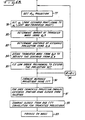
- Turning to Fig. 6A, it is seen that the system starts operation at 70, and first produces a projection set including all angles θ at step 71, in the manner described above.
Step 72 is used to follow the entire procedure of Fig. 3 in removing the effects of obscured reference channels.Step 73 is then executed to determine the zeroeth and first order moments, Q and Q for 0 1 each projection within the set. Digressing to Fig. 5, the nature of the moment of a projection set will briefly be discussed. The equation for calculating a moment is:
zeroeth order moment 55 can be a sinusoidal-like function with no more than one cycle across the set, and having relatively low amplitude. The first order moment is illustrated at 56, and can be conceptualized as related to the location of the centroid of the mass represented by the zeroeth order moment. Like the zeroeth order moment, it can vary with angle, but with only two full periods per 360 degree projection set. - In accordance with the invention, the moment information discussed above is examined to detect variations from expected behavior, to identify the views producing such variation as truncated, to estimate more likely moments for completed views, and to utilize that information in completing the truncated projections. Fig. 5 illustrates two areas where the moments behave in an unexpected fashion, those areas being bracketed at 57 and 58. It is seen that in the
area 57, the amplitude of thezeroeth order moment 00 increases in an unexpected fashion and the initially well behavedfirst order moment 01 shows an unexpected undulation. Thus, each view encompassed within thearea 57 can be said to be truncated, and expected moments should be determined to compare with the actual ones for the purpose of completing the views. Thus, for the zeroeth order moment, the more or less straight line segment 60 is determined to be a better estimate of what the moment of the completed data set would have been, and the straight line section 61 estimated to be a more likely first order moment for the area if the projection set had been complete. Similar criteria lead to the identification of the views bracketed at 58 as being truncated, and in the estimation ofstraight.line 62 as a more likely zeroeth order moment andstraight line 63 as a more likely first order moment for the area had the views been complete. While it is convenient to use straight lines, other curves could be used if desired. - Returning to Fig. 6, the
step 74 performs the identification of theareas step 75 then determines what the moments would likely have been had the projection sets been complete as discussed above. Having made those determinations, the system then returns to each flagged view and, using the moment information detailed, above along with the information in that view, then completes the view by determining extension functions (the g ( φ)' s of Fig. 4). The latter is accomplished by fitting low order polynomials to the available information. The order of the polynomials chosen to represent gi (φ) determines the number of constraints which must be formulated. That number in turn determines the number of moments which must be calculated in the formulation. The particular embodiment described here uses first-order polnomials (i.e., straight lines), for which only Q and Q 1 need be considere - In order to determine the coefficients of the particular low order polynomials, a first constraint is placed on the extended projection set, requiring at some point that its amplitude go to zero. That is likened to the physical requirement of the body ending at some-point. Fig. 4 illustrates the points φ'1 and φ' 2 at which the extended projection set goes to zero. The actual location of φ'1 and φ'2 2 must still be determined.
- An additional two constraints are placed on the function using the zeroeth and first order moments. Having determined best estimate values for those moments above, and knowing the actual moments for the truncated projection sets, the requirement is that the measured moments be altered to conform with the expected moments.
- A final constraint found useful is that of continuity of the projection and its derivatives across boundaries between the truncated projection set and the extended projection set. That can be stated as the derivative of some order of gi with respect to φ' be equal to the derivative of pi with respect to φ at 1 and φ 2. The order of the derivatives required for this constraint is determined by the order of the polynomial. If a first order polynomial, i.e., a straight line, is chosen, then it is only necessary to insure that the completed projection is continuous at the boundary. Continuity can be accomplished by simply assigning the amplitude of the last point in the truncated set, pl or p2, to the first point in the extended set gl or g2, respectively.
- Turning to Figs. 6A and 6B, it is seen that the
steps step 78 is then accomplished as described generally above to set the value of the first point in the extended projection set to that of the last point in the truncated projection set at each end of the set. The points where that operation is accomplished are illustrated at 79, 80 of Fig. 4. - The system then proceeds to a
step 82 which determines the amount of mass which was truncated by using the zeroeth order moment information. More particularly, recalling Fig. 5, and assuming the system is operating on a view within the bracketedportion 57, the system would determine the difference between the estimated zeroeth order moment 60 and the corresponding measured moment from the truncated data. -
Step 83 is then performed to determine the centroid of the total amount of mass in the extended projection set using the first order moment information fromstep 75. The physical significance of that can be appreciated with respect to Fig. 4. Recalling that thepoints step 82 determines the total area under the curves g, φ) and g2 ( φ). In order to further define those functions, thestep 83 determines where the center of mass for the entire projection set should be, and from that information the area under the curves gl (φ) and g2 (φ) can be apportioned. That is accomplished in astep 85 by fitting a low order polynomial to the extended projection set, thus defining in the illustrated embodiment g1 (φ) and g2 ( φ) by requiring them to be straight lines, and by determining their slope and intercept. Astep 86 then selects the next truncated projection and repeats the entire procedure. The end result is the completion of each truncated projection with estimated data most likely to satisfy at least the low frequency continuity requirements of the reconstruction algorithm. - The manipulative steps set out in connection with Figs. 6A and 6B can also be described mathematically, and a discussion thereof will be provided as an aid in programming the reconstruction computer to perform the method according to the present invention. First of all, the straight line to be defined for the extended function, g1 (φ) or g2 (φ), or generally gi (φ) where i is 1 or 2, can be defined as:

- The coefficients ai and bi are to be determined in order to define the function. The continuity of the projection requires that:

points 

- In addition, a function δi can be defined, relating to the horizontal coordinate of the extension function (φ'i-φi), and that can be set equal to the intercept and slope as set out in equation 4 yielding the following:

- The
steps 
- set. That difference is the quantity which must be divided between the extension functions, as set out for the g1(?) and g2 (φ) integrals over the extended function.
- Equation 18 can be manipulated to yield a form more adaptable to utilizing the moment and view information in determining the coefficients of the extended function. After some manipulation, and utilizing both the zeroeth and first order moments, equation 7 leads to:


- Elimination of ξ1 leads to:

- Using the conventional formula for solution of a quadratic, and solving equation 11 for ξ 2 yields:

- finally, using ξ2 to solve for ξ 1, the inverse of the slope of the extended function, yields:

- Having first determined the actual truncated moments and expected moments had the projection in question not. been truncated, it will now be apparent that any view can be accessed and completed simply using the moment information and the data from the view in question. First of all, it is first necessary to use the amplitudes of the
points 80 and 81 (Fig. 4) identified as p1 and p2, the zero and first order moments R0 and R1, and the channel angle at truncation φ1 and φ2 to compute the coefficients set out inequation 12. Those coefficients are then used inequation 13 to calculate ξ following which ξ 2 is used inequation 14 to calculate ξ1. The intercepts are provided by equation 4, and using only the information within that view, the coefficients for the functions gl (φ) and 92 φ) are determined to complete the truncated data set. - It is noted that a special case can exist where the projection is truncated on only one side. In that case, it is only necessary to apply
equation 3 and the first moment Equation (7) to find the slope. In the case where the left end of the projection is missing, the inverse of the slope is determined by:
- Thus, the coefficients of the two extension functions are completely determined, and in combination with the original truncated projection defines an extended projection which will satisfy at least the low frequency continuity requirements of the reconstruction algorithm.
- It is then possible to use that extended function by convolvi it with the standard convolution filter to produce a filtered data set used in back projection to reconstruct an image. However in many modern CT scanners, convolution is performed in the Fourie. domain, first using a Fast Fourier Transform followed by a multiplication and an inverse transform before back projection.
- In a particular CT scanner, a 1024 point FFT is used on non-truncated data sets having about 511 elements to avoid wrap-around. It is thus not unlikely to assume that extending a projection set as described above will increase the data set such that a 1024 point FFT will not be sufficient. To use standard convolution techniques for that extended data set would therefore require at least a 2048 point FFT, approximately doubling the time necessary to make the transform.
- In accordance with a particular aspect of the invention, that difficulty is avoided by using conventional FFT convolution for the non-truncated portion of the data set and using an approximate closed form solution for the extended portion, then combining the two convolutions to produce a modified projection set for back projection. Thus, returning to Fig. 6B, a
step 90 convolves each of the measured projection sets whether truncated or not. Then, a step 91 selects each of the truncated sets and performs a closed form solution for convolution of the extension. A step 02 then combines that closed form convolution with the FFT convolution ofstep 90 for each truncated projection set in order to produce a more accurate set of filtered data taking into account the body portions beyond the field of view. Thestep 93 then performs the normal procedures used for producing an image, typically back projection. - The convolution of the extended portion, which it is desired to evaluate can be set out as follows:

φ 1 and φ 2. When a specific kernel is chosen, in the present example that which has come to be known as the LAKS kernel,equation 17 can be evaluated in closed form. First of all, it can be approximated as:
- Then for:

- the Fourier transform is:
- Thus, for the LAKS kernel the convolution can be stated as:


- The use of "LAKS" kernel for fan-beam geometry is not strictly valid. We have found that the error so produced is negligible inasmuch as only low spatial frequencies are recovered by the extension process.
- Experimentation with the procedures described herein, in which the first two moments of the extended projections are made consistent with the other views, has shown that shading artifacts caused by truncated views can be significantly reduced. Furthermore, using the closed form solution for evaluation of the convolution of the extensions of the projection sets accomplishes that result without an unacceptable increase in processing time.
Claims (9)
Applications Claiming Priority (2)
| Application Number | Priority Date | Filing Date | Title |
|---|---|---|---|
| US424501 | 1982-09-27 | ||
| US06/424,501 US4550371A (en) | 1982-09-27 | 1982-09-27 | Method and apparatus for compensating CT images for truncated projections |
Publications (3)
| Publication Number | Publication Date |
|---|---|
| EP0106964A2 true EP0106964A2 (en) | 1984-05-02 |
| EP0106964A3 EP0106964A3 (en) | 1986-02-12 |
| EP0106964B1 EP0106964B1 (en) | 1990-03-28 |
Family
ID=23682857
Family Applications (1)
| Application Number | Title | Priority Date | Filing Date |
|---|---|---|---|
| EP19830108168 Expired - Lifetime EP0106964B1 (en) | 1982-09-27 | 1983-08-18 | Method and apparatus for compensating ct images for truncated projections |
Country Status (5)
| Country | Link |
|---|---|
| US (1) | US4550371A (en) |
| EP (1) | EP0106964B1 (en) |
| JP (1) | JPS5980234A (en) |
| DE (1) | DE3381384D1 (en) |
| IL (1) | IL69092A0 (en) |
Cited By (1)
| Publication number | Priority date | Publication date | Assignee | Title |
|---|---|---|---|---|
| DE102008003173A1 (en) * | 2008-01-04 | 2009-07-09 | Siemens Aktiengesellschaft | Method for computed tomography for determining an object area |
Families Citing this family (38)
| Publication number | Priority date | Publication date | Assignee | Title |
|---|---|---|---|---|
| IL69327A (en) * | 1983-07-26 | 1986-11-30 | Elscint Ltd | Automatic misregistration correction |
| US4606004A (en) * | 1984-03-21 | 1986-08-12 | General Electric Company | Apparatus for reduction of filtration truncation errors |
| JPS60220050A (en) * | 1984-04-17 | 1985-11-02 | 横河メディカルシステム株式会社 | Calculator tomography apparatus |
| US4674045A (en) * | 1984-12-31 | 1987-06-16 | Picker International Inc. | Filter for data processing |
| US4809172A (en) * | 1987-03-11 | 1989-02-28 | Kabushiki Kaisha Toshiba | Method for obtaining image data with a tomographic apparatus |
| CA1274922A (en) * | 1987-09-11 | 1990-10-02 | Terence Taylor | Region of interest tomography employing a differential scanning technique |
| DE8713524U1 (en) * | 1987-10-08 | 1989-02-02 | Siemens AG, 1000 Berlin und 8000 München | Third generation computer tomograph |
| US5043890A (en) * | 1989-06-12 | 1991-08-27 | General Electric | Compensation of computed tomography data for objects positioned outside the field of view of the reconstructed image |
| US5225980A (en) * | 1991-11-27 | 1993-07-06 | General Electric Company | Reduction of image artifacts from support structures in tomographic imaging |
| US5241576A (en) * | 1991-12-23 | 1993-08-31 | General Electric Company | Segmented detector containing sub-elements for separate measuring of a fan beam |
| US5485492A (en) * | 1992-03-31 | 1996-01-16 | Lunar Corporation | Reduced field-of-view CT system for imaging compact embedded structures |
| US6701000B1 (en) * | 1999-04-30 | 2004-03-02 | General Electric Company | Solution to detector lag problem in a solid state detector |
| US6879656B2 (en) * | 2002-07-23 | 2005-04-12 | General Electric Company | Method and apparatus for deriving motion information from projection data |
| US6810102B2 (en) * | 2002-10-04 | 2004-10-26 | Ge Medical Systems Global Technology Company, Llc | Methods and apparatus for truncation compensation |
| US7254259B2 (en) * | 2002-10-04 | 2007-08-07 | Ge Medical Systems Global Technology Company Llc | Methods and apparatus for truncation compensation |
| US6856666B2 (en) * | 2002-10-04 | 2005-02-15 | Ge Medical Systems Global Technology Company, Llc | Multi modality imaging methods and apparatus |
| EP1741062B1 (en) * | 2004-04-21 | 2013-02-13 | Philips Intellectual Property & Standards GmbH | Cone beam ct apparatus using truncated projections and a previously acquired 3d ct image |
| US7050528B2 (en) * | 2004-09-30 | 2006-05-23 | Wisconsin Alumni Research Foundation | Correction of CT images for truncated or incomplete projections |
| JP2006102299A (en) * | 2004-10-07 | 2006-04-20 | Ge Medical Systems Global Technology Co Llc | X-ray dose correcting method and x-ray ct apparatus |
| US7359478B2 (en) * | 2004-11-18 | 2008-04-15 | Toshiba Medical Systems Corporation | Method for restoring truncated helical cone-beam computed tomography data |
| JP2008525142A (en) * | 2004-12-29 | 2008-07-17 | コーニンクレッカ フィリップス エレクトロニクス エヌ ヴィ | Apparatus and method for x-ray projection artifact correction |
| KR100687846B1 (en) * | 2005-01-21 | 2007-02-27 | 경희대학교 산학협력단 | Local high resolution x-ray tomography image reconstruction method and local high resolution x-ray tomography image reconstruction apparatus |
| JP2006312027A (en) * | 2005-04-05 | 2006-11-16 | Toshiba Corp | Radiation diagnostic equipment |
| US7502440B2 (en) * | 2005-04-05 | 2009-03-10 | Kabushiki Toshiba | Radiodiagnostic apparatus |
| US20070076933A1 (en) * | 2005-09-30 | 2007-04-05 | Jared Starman | Estimating the 0th and 1st moments in C-arm CT data for extrapolating truncated projections |
| US7756315B2 (en) * | 2005-11-23 | 2010-07-13 | General Electric Company | Method and apparatus for field-of-view expansion of volumetric CT imaging |
| US7515678B2 (en) * | 2005-11-23 | 2009-04-07 | General Electric Company | Method and system for performing CT image reconstruction with motion artifact correction |
| US8340241B2 (en) * | 2006-02-27 | 2012-12-25 | Kabushiki Kaisha Toshiba | Image display apparatus and X-ray computed tomography apparatus |
| DE102006014629A1 (en) * | 2006-03-29 | 2007-10-04 | Siemens Ag | Truncation artifacts correction method in tomographic imaging, e.g. for medical diagnosis, determining extrapolated pixel outside projection image based on radiation attenuation of equivalent body placed in edge region of image |
| JP2008220653A (en) * | 2007-03-13 | 2008-09-25 | Toshiba Corp | X-ray CT apparatus, object outline estimation method, and image reconstruction method |
| DE102007054079A1 (en) * | 2007-11-13 | 2009-05-20 | Siemens Ag | Method for extrapolating truncated, incomplete projections for computed tomography |
| KR100923094B1 (en) * | 2008-01-15 | 2009-10-22 | (주)이우테크놀로지 | How to calibrate truncation artifacts |
| US8213694B2 (en) * | 2008-02-29 | 2012-07-03 | Barco N.V. | Computed tomography reconstruction from truncated scans |
| RU2568321C2 (en) * | 2009-08-20 | 2015-11-20 | Конинклейке Филипс Электроникс Н.В. | Reconstruction of region-of-interest image |
| DE102009047867B4 (en) * | 2009-09-30 | 2016-10-06 | Siemens Healthcare Gmbh | Method and device for correcting truncated projection data |
| US8238518B2 (en) * | 2010-06-23 | 2012-08-07 | The Institute Of Cancer Research | Radiotherapy system |
| DE102012207629B4 (en) * | 2012-05-08 | 2023-01-05 | Siemens Healthcare Gmbh | CT image reconstruction in the extended measuring field |
| US9224216B2 (en) * | 2013-07-31 | 2015-12-29 | Kabushiki Kaisha Toshiba | High density forward projector for spatial resolution improvement for medical imaging systems including computed tomography |
Family Cites Families (8)
| Publication number | Priority date | Publication date | Assignee | Title |
|---|---|---|---|---|
| GB1584954A (en) * | 1976-08-17 | 1981-02-18 | Emi Ltd | Radiography |
| DE2753260A1 (en) * | 1977-11-30 | 1979-05-31 | Philips Patentverwaltung | METHOD FOR DETERMINING THE SPATIAL DISTRIBUTION OF THE ABSORPTION OF RADIATION |
| DE2926456A1 (en) * | 1979-06-30 | 1981-01-15 | Philips Patentverwaltung | METHOD FOR DETERMINING THE EDGE OF A BODY BY MEANS OF SPRAYED RADIATION |
| JPS5672849A (en) * | 1979-11-21 | 1981-06-17 | Hitachi Medical Corp | Method of regenerating tomographing image |
| US4305127A (en) * | 1979-11-29 | 1981-12-08 | Technicare Corporation | Projection completion method of partial area scan |
| DE3012648A1 (en) * | 1980-04-01 | 1981-10-08 | Philips Patentverwaltung Gmbh, 2000 Hamburg | COMPUTER TOMOGRAPHY UNIT |
| FR2519772B1 (en) * | 1982-01-08 | 1986-01-31 | Thomson Csf | REFERENCE DETECTION DEVICE FOR MULTIDETECTOR TOMODENSITOMETER AND TOMODENSITOMETER COMPRISING SUCH A DEVICE |
| US4472823A (en) * | 1982-03-17 | 1984-09-18 | U.S. Philips Corporation | Computed tomography apparatus with detector sensitivity correction |
-
1982
- 1982-09-27 US US06/424,501 patent/US4550371A/en not_active Expired - Lifetime
-
1983
- 1983-06-28 IL IL69092A patent/IL69092A0/en not_active IP Right Cessation
- 1983-08-18 DE DE8383108168T patent/DE3381384D1/en not_active Expired - Lifetime
- 1983-08-18 EP EP19830108168 patent/EP0106964B1/en not_active Expired - Lifetime
- 1983-09-27 JP JP58177177A patent/JPS5980234A/en active Granted
Cited By (3)
| Publication number | Priority date | Publication date | Assignee | Title |
|---|---|---|---|---|
| DE102008003173A1 (en) * | 2008-01-04 | 2009-07-09 | Siemens Aktiengesellschaft | Method for computed tomography for determining an object area |
| US8150131B2 (en) | 2008-01-04 | 2012-04-03 | Siemens Aktiengesellschaft | Computer tomography method for determining an object region with the aid of projection images |
| DE102008003173B4 (en) * | 2008-01-04 | 2016-05-19 | Siemens Aktiengesellschaft | Method and device for computed tomography for |
Also Published As
| Publication number | Publication date |
|---|---|
| DE3381384D1 (en) | 1990-05-03 |
| EP0106964B1 (en) | 1990-03-28 |
| JPS5980234A (en) | 1984-05-09 |
| IL69092A0 (en) | 1983-10-31 |
| US4550371A (en) | 1985-10-29 |
| JPH0446578B2 (en) | 1992-07-30 |
| EP0106964A3 (en) | 1986-02-12 |
Similar Documents
| Publication | Publication Date | Title |
|---|---|---|
| EP0106964B1 (en) | Method and apparatus for compensating ct images for truncated projections | |
| US4709333A (en) | Method and apparatus for imaging in the presence of multiple high density objects | |
| US6094467A (en) | Method for improving CT images having high attenuation objects | |
| US4590558A (en) | Method and apparatus for removing objects from CT images | |
| US7254259B2 (en) | Methods and apparatus for truncation compensation | |
| US5287276A (en) | Localized motion artifact reduction in projection imaging | |
| US5640436A (en) | Method and apparatus for X-ray computed tomography | |
| US4703424A (en) | Method and means of correcting for a shift in the center of rotation of a rotating fan beam CT system | |
| US4812983A (en) | Method and means of correcting for a shift in the center of rotation of a rotating fan beam CT system | |
| US6130929A (en) | Method for eliminating artifacts in scanning electron beam computed tomographic images due to cone beam geometry | |
| EP0544507A2 (en) | Over-range image artifact reduction in tomographic imaging | |
| US4225789A (en) | Device for computer tomography | |
| US5970112A (en) | Smart collimation based on a single scout scan in a computed tomography system | |
| US4809172A (en) | Method for obtaining image data with a tomographic apparatus | |
| US4984159A (en) | Method and apparatus for estimating elliptical body contours in fan beam computed tomographic systems | |
| US6819734B2 (en) | Method for removing rings and partial rings in computed tomography images | |
| US7929742B2 (en) | Method and system for computed tomographic imaging | |
| US7149276B2 (en) | System, method, and computer program product that corrects measured data | |
| US4228505A (en) | Method for computed tomography | |
| US7844096B2 (en) | Spatially localized noise adaptive smoothing of emission tomography images | |
| US5450461A (en) | Self-calibrating computed tomography imaging system | |
| US5533091A (en) | Noise suppression algorithm and system | |
| CA2010135A1 (en) | Compensation of computed tomography data for objects positioned outside the field of view of the reconstructed image | |
| US5530731A (en) | Spiral scan computed tomography apparatus and method for operating same | |
| US4654796A (en) | System for computing correction factors for sensitivity differences in detector channels of an X-ray tomography apparatus |
Legal Events
| Date | Code | Title | Description |
|---|---|---|---|
| PUAI | Public reference made under article 153(3) epc to a published international application that has entered the european phase |
Free format text: ORIGINAL CODE: 0009012 |
|
| AK | Designated contracting states |
Designated state(s): DE FR GB NL |
|
| 17P | Request for examination filed |
Effective date: 19840818 |
|
| PUAL | Search report despatched |
Free format text: ORIGINAL CODE: 0009013 |
|
| AK | Designated contracting states |
Designated state(s): DE FR GB NL |
|
| 17Q | First examination report despatched |
Effective date: 19880516 |
|
| GRAA | (expected) grant |
Free format text: ORIGINAL CODE: 0009210 |
|
| AK | Designated contracting states |
Kind code of ref document: B1 Designated state(s): DE FR GB NL |
|
| ET | Fr: translation filed | ||
| REF | Corresponds to: |
Ref document number: 3381384 Country of ref document: DE Date of ref document: 19900503 |
|
| PGFP | Annual fee paid to national office [announced via postgrant information from national office to epo] |
Ref country code: GB Payment date: 19900626 Year of fee payment: 8 |
|
| PGFP | Annual fee paid to national office [announced via postgrant information from national office to epo] |
Ref country code: FR Payment date: 19900814 Year of fee payment: 8 |
|
| PGFP | Annual fee paid to national office [announced via postgrant information from national office to epo] |
Ref country code: NL Payment date: 19900831 Year of fee payment: 8 |
|
| PLBE | No opposition filed within time limit |
Free format text: ORIGINAL CODE: 0009261 |
|
| STAA | Information on the status of an ep patent application or granted ep patent |
Free format text: STATUS: NO OPPOSITION FILED WITHIN TIME LIMIT |
|
| 26N | No opposition filed | ||
| PG25 | Lapsed in a contracting state [announced via postgrant information from national office to epo] |
Ref country code: GB Effective date: 19910818 |
|
| PG25 | Lapsed in a contracting state [announced via postgrant information from national office to epo] |
Ref country code: NL Effective date: 19920301 |
|
| GBPC | Gb: european patent ceased through non-payment of renewal fee | ||
| NLV4 | Nl: lapsed or anulled due to non-payment of the annual fee | ||
| PG25 | Lapsed in a contracting state [announced via postgrant information from national office to epo] |
Ref country code: FR Effective date: 19920430 |
|
| REG | Reference to a national code |
Ref country code: FR Ref legal event code: ST |
|
| PGFP | Annual fee paid to national office [announced via postgrant information from national office to epo] |
Ref country code: DE Payment date: 19950725 Year of fee payment: 13 |
|
| PG25 | Lapsed in a contracting state [announced via postgrant information from national office to epo] |
Ref country code: DE Effective date: 19970501 |