EP0106657B1 - Ballastic type wire printing head - Google Patents
Ballastic type wire printing head Download PDFInfo
- Publication number
- EP0106657B1 EP0106657B1 EP83306166A EP83306166A EP0106657B1 EP 0106657 B1 EP0106657 B1 EP 0106657B1 EP 83306166 A EP83306166 A EP 83306166A EP 83306166 A EP83306166 A EP 83306166A EP 0106657 B1 EP0106657 B1 EP 0106657B1
- Authority
- EP
- European Patent Office
- Prior art keywords
- printing head
- disc
- transverse
- support
- wires
- Prior art date
- Legal status (The legal status is an assumption and is not a legal conclusion. Google has not performed a legal analysis and makes no representation as to the accuracy of the status listed.)
- Expired
Links
Images


Classifications
-
- B—PERFORMING OPERATIONS; TRANSPORTING
- B41—PRINTING; LINING MACHINES; TYPEWRITERS; STAMPS
- B41J—TYPEWRITERS; SELECTIVE PRINTING MECHANISMS, i.e. MECHANISMS PRINTING OTHERWISE THAN FROM A FORME; CORRECTION OF TYPOGRAPHICAL ERRORS
- B41J2/00—Typewriters or selective printing mechanisms characterised by the printing or marking process for which they are designed
- B41J2/22—Typewriters or selective printing mechanisms characterised by the printing or marking process for which they are designed characterised by selective application of impact or pressure on a printing material or impression-transfer material
- B41J2/23—Typewriters or selective printing mechanisms characterised by the printing or marking process for which they are designed characterised by selective application of impact or pressure on a printing material or impression-transfer material using print wires
- B41J2/235—Print head assemblies
-
- B—PERFORMING OPERATIONS; TRANSPORTING
- B41—PRINTING; LINING MACHINES; TYPEWRITERS; STAMPS
- B41J—TYPEWRITERS; SELECTIVE PRINTING MECHANISMS, i.e. MECHANISMS PRINTING OTHERWISE THAN FROM A FORME; CORRECTION OF TYPOGRAPHICAL ERRORS
- B41J29/00—Details of, or accessories for, typewriters or selective printing mechanisms not otherwise provided for
- B41J29/377—Cooling or ventilating arrangements
Definitions
- the present invention relates to a ballistic type wire printing head comprising a metallic front support having a transverse flange, and a longitudinal inner cavity, a plurality of wires axially displacable in the front support through transverse guide plates mounted in the longitudinal inner cavity, a group of electromagnetic units arranged to impel the wires and comprising a support, a plurality of ferromagnetic cores fixed to the support, a plurality of energizable coils wound on the ferromagnetic cores, and a plurality of ferromagnetic armatures associated with said plurality of ferromagnetic cores and coupled with said plurality of wires.
- a printing head of this type in which the enlarged pole portions of each electromagnetic unit are mounted individually on a metal support plate which is disposed transversely with respect to the wires.
- Mounted at the centre of the metal plate is a longitudinal support of plastics material, the function of which is to guide the wires along predetermined paths in the section between the armatures of the electromagnetic units and the front part of the head.
- the head also comprises a second group of electromagnetic units, the armatures of which are associated with another series of wires which are guided by the same longitudinal support and the enlarged pole portions of which are mounted individually on a second metal support plate which is disposed parallel to the first and secured thereto by means of screws.
- the head has the advantage of being modular in nature, insofar as the second metal support plate, the associated group of electromagnetic units and the second series of wires can be removed without modifying the adjustment of the first group of wires and electromagnetic units, the head suffers from the disadvantage of having a very high number of parts which must be mounted individually of each other. In addition, the head is also heavy, cumbersome and bulky and is not suited for use in small-size, low-cost printers or typewriters.
- DE-A-2807337 discloses a ballistic type wire printing head according to the preamble of claim 1, comprising a metallic front support having a transverse flange, and a longitudinal inner cavity, a plurality of wires axially displaceable in the front support through transverse guide plates mounted in the longitudinal inner cavity, a group of electromagnetic units arranged to impel the wires and comprising a support, a plurality of ferromagnetic cores fixed to the support, a plurality of energizable coils wound on theferromagnetic cores, and a plurality of ferromagnetic armatures associated with said plurality of ferromagnetic cores and coupled with said plurality of wires.
- Further examples of known printing heads are shown in US-A-4252449, US-A-4244658 and WO-A-81/00829. Due to their construction, all these known printing heads suffer from poor heat dissipation.
- the printing head is characterised in that said support comprises a transverse disc of ferromagnetic material to which is fixed said plurality of ferromagnetic cores, in that said metallic front support has a rear longitudinal portion extending through said transverse disc, and by a plurality of ferromagnetic longitudinally extending fin portions, protruding from said transverse disc radially disposed about said rear longitudinal portion, and associated with said cores, by an outer cavity in said front support for accommodating said transverse disc, and having a rear annular shoulder contacting said transverse disc, a support disc of nonmagnetic material having a plurality of openings for receiving ends of the longitudinal fin portions, and a second plurality of openings for housing the ends of the ferromagnetic cores, said support disc abutting the end of said rear longitudinal portion, a metallic cover abutting the transverse flange and said support disc, and a plurality of fixing members for attaching said transverse flange to the metallic cover externally
- the printing head is characterised in that it comprises a pair of printing heads according to claim 1, a second printing head being arranged immediately behind a first printing head in an axial direction, the first printing head having an intermediate cover member, said intermediate member forming the metallic front support of the second printing head and having a rear longitudinal portion extending through the transverse disc of the second printing head, the intermediate cover member having a cavity accommodating the transverse disc of the second printing head, said disc abutting a rear annular shoulder of said cover member for dissipating heat developed during energisation of the second printing head to said intermediate cover, the wires of the second printing head extending through the rear longitudinal portions of the first and second printing heads, whereby all the needles of the first and second printing heads emerge from the forward end of the front support of the first printing head.
- a printing head embodying either aspect of the invention may be modular, light, small in size and very-compact, at the same time it may provide very good dissipation of the heat produced by energisation of the coils of the actuating electromagnetic units.
- a printing head 10 in a first embodiment, comprises a front support 11 made of a metal which can be easily shaped by means of pressure di- casting, for example zamak alloy, which is shaped in such a way as to provide a central flange 12 (see Figure 3), a front portion 13 which is substantially of an inverted U-shape (see Figure 4) and a rear portion 14 (see Figure 3) which is of substantially cylindrical shape.
- Zamak is a zinc, aluminium alloy containing about 4% aluminium, 0.04% magnesium and up to 3% copper.
- the support 11 has a longitudinal cavity 15 and four transverse plates 18, 19, 20 and 21 of plastics material are fitted into and stuck in the cavity 15, being parallel to each other.
- Each of the four transverse plates 18, 19, 20 and 21 is provided with holes 22 therethrough to act as a guide for a plurality of metal printing wires 23.
- the central flange 12 of the support 11 is so shaped as to define two cylindrical cavities 30 and 31 and a circular shoulder 32 (see Figure 3).
- transverse disc 34 of an internal support 35 of ferromagnetic material Disposed in the cylindrical cavity 31 and in contact with the circular shoulder 32 is a transverse disc 34 of an internal support 35 of ferromagnetic material, which has a series of longitudinal fin portions 36 which are angularly equally spaced from each other.
- the number of fin portions 36 is equal to the number of printing wires 23.
- Cylindrical cores 37 which are also of ferromagnetic material, are riveted to the transverse disc 34, in association with the fin portions 36 respectively and parallel thereto. Each core 37 is encircled by a corresponding energisation coil 39.
- armatures 41 which are disposed in a radiating configuration and which each co-operate with a corresponding fin portion 36, a core 37 and the inner ends of a wire 23.
- armatures 41 Interposed between the armatures 41 and the disc 40 is a sheet 45 of plastics material, which is some hundredths of a millimetre in thickness.
- the cores 37, the coils 39, the fin portions 36 and the armatures 40 form a series of electromagnetic actuating units associated with the printing wires 23.
- the transverse disc 40 has a central hole 42, within which is housed the more inward end of the rear portion 14 of the support 11, and a series of nine through holes 44, within each of which is housed the end of a core 37. Also provided in the disc 40, at the periphery thereof, are nine through apertures 46 in which the ends of the fin portions 36 are fixed.
- Each armature 41 comprises two side lugs 50 and 51 which are housed in corresponding seats 52 and 53 in the transverse disc 40.
- Two resilient teeth 54 prevent each armature 41 from coming out of the seats 52 and 53 in normal operation of the arrangement, while permitting the armature 41 to be removed and replaced if required.
- Each printing wire 23 has its inward end rigidly connected to a cap 55 of plastics material, with which a coil spring 56 co-operates.
- the spring 56 in the rest position, holds the corresponding wire 23 in a retracted and inoperative position.
- a laminar spring spider 58 (see Figures 3 and 7) is mounted within a cover 59 and has nine radial arms 60 which each co-operate with a corresponding armature 41 to hold the peripheral end thereof as closely as possible to the corresponding fin portion 36. Also disposed within the cover member 59 is a rubber ring 62 against which, in the rest condition, all the inward ends of the armatures 41 bear by virtue of the force of the coil springs 56 and the spring 58.
- the cover 59 which is also made of zamak alloy, is fixed to the front support 11 by means of four screws 63 (see Figures 1, 2 and 4).
- a disc 70 of insulating material Housed in the cylindrical cavity 30 in the flange 12 is a disc 70 of insulating material, which carries the tracks or paths 71 for the supply of electrical power for the coils 39.
- a lower projecting portion 72 of the disc 70 has terminals for connection to energising connectors (not shown).
- the disc 70 is fixed to the disc 34 of the inner support 35 by means of screws 75 (only one thereof being visible in Figure 3).
- the front portion 13 of the support 11 is provided with a bottom centering pin 73 and with two seats 74 for the screws, by means of which the printing head 10 as described hereinbefore can be mounted on a carriage of a serial printer of known type.
- the above-described printing head is assembled in the following manner:
- the wires 23 complete with the caps 55 and the coil springs 56 are first fitted into the corresponding holes 22 in the transverse plates 18, 19, 20 and 21 which are successively inserted from below into the longitudinal cavity 15 in the support 11, and secured thereto by adhesive.
- the array of electromagnetic actuating units is then fitted separately.
- the coils 39 are wound on the cylindrical cores 37.
- the disc 70 is fixed to the transverse disc 34 of the support 35 by means of the screws 75 and the terminals of the coils 39 are soldered to the electrical power supply tracks 71.
- the plastic sheet 45 and then the armatures 41 are mounted on the transverse disc 40.
- the disc 40 is then mounted to the ferromagnetic support 35 in such a way that the cores 37 are inserted into the holes 44 and the fin portions 36 are firmly fitted into the openings 46.
- the group of electromagnetic units which is formed in that way, is then mounted on the rear portion 14 of the support 11, in such a way that the disc 70 is housed in the cylindrical cavity 30 and the disc 35 bears against the circular shoulder 32 on the flange 12.
- the cover member 59 on which the inner ring 62 and the spring 58 have been previously disposed is then fixed to the support 11 by means of the screws 63.
- the above-described printing head 10 is very compact, light and small in size, the weight thereof being about 120 grams while its length is 45 mm and its maximum transverse dimension is 40 mm, as well as being particularly suitable for use in office typewriters.
- the printing head 10 operates in known manner, by means of movement thereof parallel to a platen roller, and selective actuation of the electromagnetic units associated with the wires 23. More precisely, whenever one of the coils 39 has a current flowing therethrough, a magnetic flux is generated in the core 37, which causes the corresponding armature 41 to be attracted towards that core 37, and thus produces axial movement of the wire 23 associated therewith, which ballistically continues its forward travel, even after the armature 41 has been stopped against the sheet 45 which is interposed between the armatures and the cores 37. After a dot has been printed, the rebound force of the platen and the coil spring 56 cause the wire 23 to return towards the rest position, the coil 39 having been de-energised at the moment at which the armature 41 has terminated its forward travel.
- FIGS. 8 and 9 show a second embodiment which includes a second group of electromagnetic units and print wires 23.
- a support 80 which is also made of zamak alloy is fitted in place of the cover 59.
- the support 80 is of the same configuration at its front as the cover member 59 and in fact internally supports the spring 58 and the internal ring 62, and can be secured to the support 11 by means of the screws 63.
- the front portion 81 of the support 80 is substantially identical to the flange 12 and the portion 14 of the support 11.
- the support 80 is of such a configuration as to define two cylindrical cavities 83 and 84 and a circular shoulder 85.
- the support 80 also has a longitudinal cavity 86 in which two further transverse plates 87 and 88 of plastics material are inserted and secured by adhesive, being parallel to each other.
- Each of the plates 87 and 88 is provided with holes 89 therethrough, to guide a second series of metal printing wires 23.
- the second series of wires comprises nine further wires.
- a second group 90 of electromagnetic units Disposed in the cylindrical cavity 84, and bearing against the circular shoulder 85, is a second group 90 of electromagnetic units identical to that described hereinbefore, which can cooperate with the second series of printing wires 23.
- the cover 59 which is provided with another spring 58 and another internal rubber ring 62 is fitted so as to cover the second group of electromagnetic units, and secured to the support 80 by means of four screws 91.
- transverse plates 18, 19, 20 and 21 are provided with holes 22 also for guiding the second series of wires 23.
- the wires are guided in such a way that their printing ends are aligned in two parallel columns.
- This second embodiment of the head 10 is also very compact, light and small in size, weighing about 200 grams and being about 72 mm in length, while its maximum transverse dimensions are equal to those of the first embodiment.
- the heat developed by energization of the coils 39 is dissipated to the exterior by virtue of their structure and in particular to the fact that the internal support 35 of the group of electromagnetic units is in contact with the transverse flange 12 of the front metal support 11.
Landscapes
- Impact Printers (AREA)
- Accessory Devices And Overall Control Thereof (AREA)
Description
- The present invention relates to a ballistic type wire printing head comprising a metallic front support having a transverse flange, and a longitudinal inner cavity, a plurality of wires axially displacable in the front support through transverse guide plates mounted in the longitudinal inner cavity, a group of electromagnetic units arranged to impel the wires and comprising a support, a plurality of ferromagnetic cores fixed to the support, a plurality of energizable coils wound on the ferromagnetic cores, and a plurality of ferromagnetic armatures associated with said plurality of ferromagnetic cores and coupled with said plurality of wires.
- A printing head of this type is known, in which the enlarged pole portions of each electromagnetic unit are mounted individually on a metal support plate which is disposed transversely with respect to the wires. Mounted at the centre of the metal plate is a longitudinal support of plastics material, the function of which is to guide the wires along predetermined paths in the section between the armatures of the electromagnetic units and the front part of the head. The head also comprises a second group of electromagnetic units, the armatures of which are associated with another series of wires which are guided by the same longitudinal support and the enlarged pole portions of which are mounted individually on a second metal support plate which is disposed parallel to the first and secured thereto by means of screws.
- While such a head has the advantage of being modular in nature, insofar as the second metal support plate, the associated group of electromagnetic units and the second series of wires can be removed without modifying the adjustment of the first group of wires and electromagnetic units, the head suffers from the disadvantage of having a very high number of parts which must be mounted individually of each other. In addition, the head is also heavy, cumbersome and bulky and is not suited for use in small-size, low-cost printers or typewriters.
- DE-A-2807337 discloses a ballistic type wire printing head according to the preamble of claim 1, comprising a metallic front support having a transverse flange, and a longitudinal inner cavity, a plurality of wires axially displaceable in the front support through transverse guide plates mounted in the longitudinal inner cavity, a group of electromagnetic units arranged to impel the wires and comprising a support, a plurality of ferromagnetic cores fixed to the support, a plurality of energizable coils wound on theferromagnetic cores, and a plurality of ferromagnetic armatures associated with said plurality of ferromagnetic cores and coupled with said plurality of wires. Further examples of known printing heads are shown in US-A-4252449, US-A-4244658 and WO-A-81/00829. Due to their construction, all these known printing heads suffer from poor heat dissipation.
- In accordance with a first aspect of the present invention, the printing head is characterised in that said support comprises a transverse disc of ferromagnetic material to which is fixed said plurality of ferromagnetic cores, in that said metallic front support has a rear longitudinal portion extending through said transverse disc, and by a plurality of ferromagnetic longitudinally extending fin portions, protruding from said transverse disc radially disposed about said rear longitudinal portion, and associated with said cores, by an outer cavity in said front support for accommodating said transverse disc, and having a rear annular shoulder contacting said transverse disc, a support disc of nonmagnetic material having a plurality of openings for receiving ends of the longitudinal fin portions, and a second plurality of openings for housing the ends of the ferromagnetic cores, said support disc abutting the end of said rear longitudinal portion, a metallic cover abutting the transverse flange and said support disc, and a plurality of fixing members for attaching said transverse flange to the metallic cover externally of the transverse disc to hold the transverse disc in contact with said rear annular shoulder.
- In accordance with a second aspect of the present invention, the printing head is characterised in that it comprises a pair of printing heads according to claim 1, a second printing head being arranged immediately behind a first printing head in an axial direction, the first printing head having an intermediate cover member, said intermediate member forming the metallic front support of the second printing head and having a rear longitudinal portion extending through the transverse disc of the second printing head, the intermediate cover member having a cavity accommodating the transverse disc of the second printing head, said disc abutting a rear annular shoulder of said cover member for dissipating heat developed during energisation of the second printing head to said intermediate cover, the wires of the second printing head extending through the rear longitudinal portions of the first and second printing heads, whereby all the needles of the first and second printing heads emerge from the forward end of the front support of the first printing head.
- A printing head embodying either aspect of the invention may be modular, light, small in size and very-compact, at the same time it may provide very good dissipation of the heat produced by energisation of the coils of the actuating electromagnetic units.
- The invention will be described in more detail, by way of example, with reference to the accompanying drawings, in which:
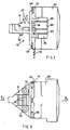
- Figure 1 is a side view of a first embodiment of a printing head according to the invention,
- Figure 2 is a plan view of the printing head shown in Figure 1,
- Figure 3 is a view in section taken along line 3-3 in Figure 2,
- Figure 4 is a front view of the printing head shown in Figure 1,
- Figure 5 is a view in section taken along line 5-5 in Figure 3,
- Figure 6 is a view in section taken along line 6-6 in Figure 5 on an enlarged scale,
- Figure 7 is a view in section taken along line 7-7 in Figure 3,
- Figure 8 is a plan view of a second embodiment of a printing head according to the invention, and
- Figure 9 is a view in section taken along line 9-9 in Figure 8.
- Referring to Figure 1, in a first embodiment, a
printing head 10 according to the invention comprises afront support 11 made of a metal which can be easily shaped by means of pressure di- casting, for example zamak alloy, which is shaped in such a way as to provide a central flange 12 (see Figure 3), afront portion 13 which is substantially of an inverted U-shape (see Figure 4) and a rear portion 14 (see Figure 3) which is of substantially cylindrical shape. Zamak is a zinc, aluminium alloy containing about 4% aluminium, 0.04% magnesium and up to 3% copper. - The
support 11 has alongitudinal cavity 15 and fourtransverse plates cavity 15, being parallel to each other. Each of the fourtransverse plates holes 22 therethrough to act as a guide for a plurality ofmetal printing wires 23. In this first embodiment, there are nineprinting wires 23 and they have their front printing ends aligned in a single column (see Figure 4). - Provided on the
front portion 13 of thesupport 12 are two uppervertical fin portions 25 for enhanced dissipation of the heat developed in operation of theprinting head 10. - The
central flange 12 of thesupport 11 is so shaped as to define twocylindrical cavities - Disposed in the
cylindrical cavity 31 and in contact with thecircular shoulder 32 is atransverse disc 34 of aninternal support 35 of ferromagnetic material, which has a series oflongitudinal fin portions 36 which are angularly equally spaced from each other. The number offin portions 36 is equal to the number ofprinting wires 23. -
Cylindrical cores 37, which are also of ferromagnetic material, are riveted to thetransverse disc 34, in association with thefin portions 36 respectively and parallel thereto. Eachcore 37 is encircled by acorresponding energisation coil 39. - Mounted on a
transverse disc 40 of plastics material (see Figures 3, 5 and 6) arearmatures 41 which are disposed in a radiating configuration and which each co-operate with a correspondingfin portion 36, acore 37 and the inner ends of awire 23. Interposed between thearmatures 41 and thedisc 40 is asheet 45 of plastics material, which is some hundredths of a millimetre in thickness. - In this way, the
cores 37, thecoils 39, thefin portions 36 and thearmatures 40 form a series of electromagnetic actuating units associated with theprinting wires 23. - The
transverse disc 40 has acentral hole 42, within which is housed the more inward end of the rear portion 14 of thesupport 11, and a series of nine through holes 44, within each of which is housed the end of acore 37. Also provided in thedisc 40, at the periphery thereof, are nine throughapertures 46 in which the ends of thefin portions 36 are fixed. - Each
armature 41 comprises twoside lugs corresponding seats transverse disc 40. Tworesilient teeth 54 prevent eacharmature 41 from coming out of theseats armature 41 to be removed and replaced if required. - Each
printing wire 23 has its inward end rigidly connected to acap 55 of plastics material, with which acoil spring 56 co-operates. Thespring 56, in the rest position, holds thecorresponding wire 23 in a retracted and inoperative position. - A laminar spring spider 58 (see Figures 3 and 7) is mounted within a
cover 59 and has nineradial arms 60 which each co-operate with acorresponding armature 41 to hold the peripheral end thereof as closely as possible to the correspondingfin portion 36. Also disposed within thecover member 59 is arubber ring 62 against which, in the rest condition, all the inward ends of thearmatures 41 bear by virtue of the force of thecoil springs 56 and thespring 58. Thecover 59, which is also made of zamak alloy, is fixed to thefront support 11 by means of four screws 63 (see Figures 1, 2 and 4). - Housed in the
cylindrical cavity 30 in theflange 12 is adisc 70 of insulating material, which carries the tracks orpaths 71 for the supply of electrical power for thecoils 39. Alower projecting portion 72 of thedisc 70 has terminals for connection to energising connectors (not shown). Thedisc 70 is fixed to thedisc 34 of theinner support 35 by means of screws 75 (only one thereof being visible in Figure 3). - The
front portion 13 of thesupport 11 is provided with abottom centering pin 73 and with twoseats 74 for the screws, by means of which theprinting head 10 as described hereinbefore can be mounted on a carriage of a serial printer of known type. - The above-described printing head is assembled in the following manner:
- The
wires 23 complete with thecaps 55 and thecoil springs 56 are first fitted into thecorresponding holes 22 in thetransverse plates longitudinal cavity 15 in thesupport 11, and secured thereto by adhesive. - The array of electromagnetic actuating units is then fitted separately.
- In particular, the
coils 39 are wound on thecylindrical cores 37. Thedisc 70 is fixed to thetransverse disc 34 of thesupport 35 by means of thescrews 75 and the terminals of thecoils 39 are soldered to the electricalpower supply tracks 71. - First the
plastic sheet 45 and then thearmatures 41 are mounted on thetransverse disc 40. Thedisc 40 is then mounted to theferromagnetic support 35 in such a way that thecores 37 are inserted into the holes 44 and thefin portions 36 are firmly fitted into theopenings 46. - The group of electromagnetic units, which is formed in that way, is then mounted on the rear portion 14 of the
support 11, in such a way that thedisc 70 is housed in thecylindrical cavity 30 and thedisc 35 bears against thecircular shoulder 32 on theflange 12. - The
cover member 59 on which theinner ring 62 and thespring 58 have been previously disposed is then fixed to thesupport 11 by means of thescrews 63. - The above-described
printing head 10 is very compact, light and small in size, the weight thereof being about 120 grams while its length is 45 mm and its maximum transverse dimension is 40 mm, as well as being particularly suitable for use in office typewriters. - The
printing head 10 operates in known manner, by means of movement thereof parallel to a platen roller, and selective actuation of the electromagnetic units associated with thewires 23. More precisely, whenever one of thecoils 39 has a current flowing therethrough, a magnetic flux is generated in thecore 37, which causes thecorresponding armature 41 to be attracted towards thatcore 37, and thus produces axial movement of thewire 23 associated therewith, which ballistically continues its forward travel, even after thearmature 41 has been stopped against thesheet 45 which is interposed between the armatures and thecores 37. After a dot has been printed, the rebound force of the platen and thecoil spring 56 cause thewire 23 to return towards the rest position, thecoil 39 having been de-energised at the moment at which thearmature 41 has terminated its forward travel. - The above-described
printing head 10 is also modular, and Figures 8 and 9 show a second embodiment which includes a second group of electromagnetic units andprint wires 23. in this second embodiment, asupport 80 which is also made of zamak alloy is fitted in place of thecover 59. - The
support 80 is of the same configuration at its front as thecover member 59 and in fact internally supports thespring 58 and theinternal ring 62, and can be secured to thesupport 11 by means of thescrews 63. - The
front portion 81 of thesupport 80 on the other hand is substantially identical to theflange 12 and the portion 14 of thesupport 11. - In particular, the
support 80 is of such a configuration as to define twocylindrical cavities 83 and 84 and acircular shoulder 85. Thesupport 80 also has alongitudinal cavity 86 in which two furthertransverse plates plates holes 89 therethrough, to guide a second series ofmetal printing wires 23. In this embodiment, the second series of wires comprises nine further wires. - Disposed in the
cylindrical cavity 84, and bearing against thecircular shoulder 85, is asecond group 90 of electromagnetic units identical to that described hereinbefore, which can cooperate with the second series ofprinting wires 23. - The
cover 59 which is provided with anotherspring 58 and anotherinternal rubber ring 62 is fitted so as to cover the second group of electromagnetic units, and secured to thesupport 80 by means of fourscrews 91. - It is obvious that in this second embodiment the
transverse plates holes 22 also for guiding the second series ofwires 23. In particular, the wires are guided in such a way that their printing ends are aligned in two parallel columns. - It will also be apparent that the number of
printing wires 23, if necessary, can be reduced in comparison with the number of wires specified hereinbefore by way of example. - Assembly and mode of operation of this second embodiment are similar to the first embodiment, and will therefore not be repeated, for the sake of brevity.
- This second embodiment of the
head 10 is also very compact, light and small in size, weighing about 200 grams and being about 72 mm in length, while its maximum transverse dimensions are equal to those of the first embodiment. - In both the above-described printing heads, the heat developed by energization of the
coils 39 is dissipated to the exterior by virtue of their structure and in particular to the fact that theinternal support 35 of the group of electromagnetic units is in contact with thetransverse flange 12 of thefront metal support 11.
Claims (6)
Applications Claiming Priority (2)
| Application Number | Priority Date | Filing Date | Title |
|---|---|---|---|
| IT68193/82A IT1156203B (en) | 1982-10-12 | 1982-10-12 | BALLISTIC TYPE PRINT HEAD |
| IT6819382 | 1982-10-12 |
Publications (3)
| Publication Number | Publication Date |
|---|---|
| EP0106657A2 EP0106657A2 (en) | 1984-04-25 |
| EP0106657A3 EP0106657A3 (en) | 1985-04-10 |
| EP0106657B1 true EP0106657B1 (en) | 1989-05-24 |
Family
ID=11308429
Family Applications (1)
| Application Number | Title | Priority Date | Filing Date |
|---|---|---|---|
| EP83306166A Expired EP0106657B1 (en) | 1982-10-12 | 1983-10-12 | Ballastic type wire printing head |
Country Status (5)
| Country | Link |
|---|---|
| US (1) | US4602881A (en) |
| EP (1) | EP0106657B1 (en) |
| JP (1) | JPS5993363A (en) |
| DE (1) | DE3379898D1 (en) |
| IT (1) | IT1156203B (en) |
Families Citing this family (10)
| Publication number | Priority date | Publication date | Assignee | Title |
|---|---|---|---|---|
| JPS6164459A (en) * | 1984-09-07 | 1986-04-02 | Citizen Watch Co Ltd | Printing head of dot line printer |
| US4561790A (en) * | 1985-01-28 | 1985-12-31 | International Business Machines Corporation | Wire matrix print head apparatus |
| JPS62101459A (en) * | 1985-10-29 | 1987-05-11 | Nhk Spring Co Ltd | Printer head |
| JPS62109673A (en) * | 1985-11-08 | 1987-05-20 | Hitachi Koki Co Ltd | Cooling device for hammer coil |
| FR2597789A1 (en) * | 1986-04-25 | 1987-10-30 | Comadur Sa | Printing head for a dot-matrix printer |
| IT1219113B (en) * | 1988-03-16 | 1990-05-03 | Olivetti & Co Spa | CARTRIDGE FOR A WRITING TAPE |
| EP0440469B1 (en) * | 1990-02-02 | 1995-06-28 | Canon Kabushiki Kaisha | Ink jet recording apparatus and ink jet recording head |
| DE69104395T2 (en) * | 1990-03-13 | 1995-02-09 | Seiko Epson Corp | Nail dot print head for impact printers. |
| JP2548587Y2 (en) * | 1990-11-30 | 1997-09-24 | シチズン時計株式会社 | Printer print head |
| CN104369545A (en) * | 2013-08-13 | 2015-02-25 | 大连中盈科技有限公司 | Stylus printer head |
Family Cites Families (17)
| Publication number | Priority date | Publication date | Assignee | Title |
|---|---|---|---|---|
| GB1422151A (en) * | 1972-01-21 | 1976-01-21 | Nash A R B | Dampers |
| DE2342420A1 (en) * | 1973-08-22 | 1975-03-13 | Steinmetz Krischke Systemtech | MOSAIC PUSH BUTTON |
| US3904011A (en) * | 1973-10-17 | 1975-09-09 | Tele Speed Communications Inc | Printing head for matrix printer |
| US3929214A (en) * | 1974-09-18 | 1975-12-30 | D & D Ass | Wire matrix ballistic impact print head |
| DE2527186C3 (en) * | 1975-06-18 | 1980-10-09 | Philips Patentverwaltung Gmbh, 2000 Hamburg | Mosaic printer with a cylindrical housing |
| DE2807337A1 (en) * | 1977-02-22 | 1978-08-31 | Information Magnetics Corp | Matrix printer having printing wires actuated by solenoids - arranged in housing contg. viscous heat-transfer material |
| US4165940A (en) * | 1977-02-28 | 1979-08-28 | Centronics Data Computer Corp. | Free flight head assembly for dot matrix printers and the like |
| JPS54104925A (en) * | 1978-02-01 | 1979-08-17 | Suwa Seikosha Kk | Dot printer head |
| US4478528A (en) * | 1978-03-10 | 1984-10-23 | Donald G. Hebert | Wire matrix print head assembly |
| US4236837A (en) * | 1978-04-14 | 1980-12-02 | Lucas Industries Limited | Operating mechanism for a dot matrix printer |
| GB2022515B (en) * | 1978-05-12 | 1982-04-21 | Suwa Seikosha Kk | Head for a dot printer |
| IT1099489B (en) * | 1978-09-11 | 1985-09-18 | Honeywell Inf Systems | PERFECTED MATRIX PRINTER HEAD |
| DE2927385C2 (en) * | 1979-07-04 | 1986-01-16 | Mannesmann AG, 4000 Düsseldorf | Hinged anchor printhead for a dot matrix printer |
| DE2939885C2 (en) * | 1979-10-02 | 1983-10-20 | Philips Patentverwaltung Gmbh, 2000 Hamburg | Dot matrix print head |
| JPS6048336B2 (en) * | 1979-10-19 | 1985-10-26 | 東芝テック株式会社 | dot printer printer head |
| US4279521A (en) * | 1979-11-02 | 1981-07-21 | International Business Machines Corporation | Wire matrix print head |
| JPS5720368A (en) * | 1980-07-11 | 1982-02-02 | Brother Ind Ltd | Printing head for dot printer |
-
1982
- 1982-10-12 IT IT68193/82A patent/IT1156203B/en active
-
1983
- 1983-10-12 DE DE8383306166T patent/DE3379898D1/en not_active Expired
- 1983-10-12 JP JP58190620A patent/JPS5993363A/en active Pending
- 1983-10-12 EP EP83306166A patent/EP0106657B1/en not_active Expired
-
1985
- 1985-06-12 US US06/743,872 patent/US4602881A/en not_active Expired - Lifetime
Also Published As
| Publication number | Publication date |
|---|---|
| IT8268193A0 (en) | 1982-10-12 |
| IT1156203B (en) | 1987-01-28 |
| US4602881A (en) | 1986-07-29 |
| DE3379898D1 (en) | 1989-06-29 |
| EP0106657A2 (en) | 1984-04-25 |
| EP0106657A3 (en) | 1985-04-10 |
| JPS5993363A (en) | 1984-05-29 |
Similar Documents
| Publication | Publication Date | Title |
|---|---|---|
| CA1083414A (en) | Matrix print head and solenoid driver | |
| US4407591A (en) | Ballistic wire matrix print head | |
| US4348120A (en) | Printing head for a dot printer | |
| EP0106657A2 (en) | Ballastic type wire printing head | |
| JPS6344551B2 (en) | ||
| EP0150607B1 (en) | Wire driving armature for dot printer | |
| US4661002A (en) | Dot matrix printer | |
| EP0274117A2 (en) | Print head incorporating a one piece armature | |
| EP0136332B1 (en) | Wire coil assembly for matrix print head and manufacturing method | |
| KR920000730Y1 (en) | Printing head for a wire dot-matrix printer | |
| CA1057575A (en) | Matrix printer comprising parallel printing pins | |
| US4737042A (en) | Printing head with springs for pivotably holding printing hammers | |
| US4572681A (en) | Wire dot print head | |
| GB2252752A (en) | Armature pivots in dot-matrix printers | |
| US4681467A (en) | Impact printing applications | |
| US4441830A (en) | Printing solenoid | |
| US4389128A (en) | Print head for a dot matrix printer | |
| US5137380A (en) | Wire-dot print head | |
| EP0030960B1 (en) | Printing apparatus and method of making same | |
| US5163761A (en) | Dot print head | |
| US5290113A (en) | Wire dot printing head | |
| JPS5842035B2 (en) | Print head for dot printer | |
| US6561707B2 (en) | Needle printing head | |
| JPH0339248Y2 (en) | ||
| JP3491869B2 (en) | Dot printer head |
Legal Events
| Date | Code | Title | Description |
|---|---|---|---|
| PUAI | Public reference made under article 153(3) epc to a published international application that has entered the european phase |
Free format text: ORIGINAL CODE: 0009012 |
|
| AK | Designated contracting states |
Designated state(s): DE FR GB |
|
| PUAL | Search report despatched |
Free format text: ORIGINAL CODE: 0009013 |
|
| AK | Designated contracting states |
Designated state(s): DE FR GB |
|
| 17P | Request for examination filed |
Effective date: 19851001 |
|
| 17Q | First examination report despatched |
Effective date: 19861028 |
|
| GRAA | (expected) grant |
Free format text: ORIGINAL CODE: 0009210 |
|
| AK | Designated contracting states |
Kind code of ref document: B1 Designated state(s): DE FR GB |
|
| REF | Corresponds to: |
Ref document number: 3379898 Country of ref document: DE Date of ref document: 19890629 |
|
| ET | Fr: translation filed | ||
| PLBE | No opposition filed within time limit |
Free format text: ORIGINAL CODE: 0009261 |
|
| STAA | Information on the status of an ep patent application or granted ep patent |
Free format text: STATUS: NO OPPOSITION FILED WITHIN TIME LIMIT |
|
| 26N | No opposition filed | ||
| PGFP | Annual fee paid to national office [announced via postgrant information from national office to epo] |
Ref country code: GB Payment date: 19971003 Year of fee payment: 15 |
|
| PGFP | Annual fee paid to national office [announced via postgrant information from national office to epo] |
Ref country code: FR Payment date: 19971009 Year of fee payment: 15 |
|
| PGFP | Annual fee paid to national office [announced via postgrant information from national office to epo] |
Ref country code: DE Payment date: 19971017 Year of fee payment: 15 |
|
| PG25 | Lapsed in a contracting state [announced via postgrant information from national office to epo] |
Ref country code: GB Free format text: LAPSE BECAUSE OF NON-PAYMENT OF DUE FEES Effective date: 19981012 |
|
| GBPC | Gb: european patent ceased through non-payment of renewal fee |
Effective date: 19981012 |
|
| PG25 | Lapsed in a contracting state [announced via postgrant information from national office to epo] |
Ref country code: FR Free format text: LAPSE BECAUSE OF NON-PAYMENT OF DUE FEES Effective date: 19990630 |
|
| REG | Reference to a national code |
Ref country code: FR Ref legal event code: ST |
|
| PG25 | Lapsed in a contracting state [announced via postgrant information from national office to epo] |
Ref country code: DE Free format text: LAPSE BECAUSE OF NON-PAYMENT OF DUE FEES Effective date: 19990803 |