EP0106602A2 - Lithium-sulphur dioxide cell and electrode therefor - Google Patents
Lithium-sulphur dioxide cell and electrode therefor Download PDFInfo
- Publication number
- EP0106602A2 EP0106602A2 EP83305883A EP83305883A EP0106602A2 EP 0106602 A2 EP0106602 A2 EP 0106602A2 EP 83305883 A EP83305883 A EP 83305883A EP 83305883 A EP83305883 A EP 83305883A EP 0106602 A2 EP0106602 A2 EP 0106602A2
- Authority
- EP
- European Patent Office
- Prior art keywords
- lithium
- cell
- anode
- copper
- sulphur dioxide
- Prior art date
- Legal status (The legal status is an assumption and is not a legal conclusion. Google has not performed a legal analysis and makes no representation as to the accuracy of the status listed.)
- Granted
Links
- GJCNZQUZWSHFHP-UHFFFAOYSA-N [Li].O=S=O Chemical compound [Li].O=S=O GJCNZQUZWSHFHP-UHFFFAOYSA-N 0.000 title claims abstract description 11
- 229910052744 lithium Inorganic materials 0.000 claims abstract description 38
- WHXSMMKQMYFTQS-UHFFFAOYSA-N Lithium Chemical compound [Li] WHXSMMKQMYFTQS-UHFFFAOYSA-N 0.000 claims abstract description 37
- RYGMFSIKBFXOCR-UHFFFAOYSA-N Copper Chemical compound [Cu] RYGMFSIKBFXOCR-UHFFFAOYSA-N 0.000 claims abstract description 26
- 229910052802 copper Inorganic materials 0.000 claims abstract description 26
- 239000010949 copper Substances 0.000 claims abstract description 26
- RAHZWNYVWXNFOC-UHFFFAOYSA-N Sulphur dioxide Chemical compound O=S=O RAHZWNYVWXNFOC-UHFFFAOYSA-N 0.000 claims description 14
- 235000010269 sulphur dioxide Nutrition 0.000 claims description 7
- 239000004291 sulphur dioxide Substances 0.000 claims description 7
- OKTJSMMVPCPJKN-UHFFFAOYSA-N Carbon Chemical compound [C] OKTJSMMVPCPJKN-UHFFFAOYSA-N 0.000 claims description 4
- 229910052799 carbon Inorganic materials 0.000 claims description 4
- 239000004615 ingredient Substances 0.000 claims description 2
- 238000004519 manufacturing process Methods 0.000 claims description 2
- HBBGRARXTFLTSG-UHFFFAOYSA-N Lithium ion Chemical compound [Li+] HBBGRARXTFLTSG-UHFFFAOYSA-N 0.000 claims 1
- 239000000463 material Substances 0.000 claims 1
- 238000013022 venting Methods 0.000 abstract description 7
- 238000004880 explosion Methods 0.000 abstract description 5
- 230000001627 detrimental effect Effects 0.000 abstract 1
- 238000006243 chemical reaction Methods 0.000 description 7
- 238000003487 electrochemical reaction Methods 0.000 description 4
- 229910052751 metal Inorganic materials 0.000 description 4
- 239000013626 chemical specie Substances 0.000 description 3
- 239000003792 electrolyte Substances 0.000 description 3
- 239000002184 metal Substances 0.000 description 3
- 229910000881 Cu alloy Inorganic materials 0.000 description 2
- 230000000694 effects Effects 0.000 description 2
- 239000000126 substance Substances 0.000 description 2
- IKQYSHIXSWZMKJ-UHFFFAOYSA-N S1S[CH-]CCC1 Chemical compound S1S[CH-]CCC1 IKQYSHIXSWZMKJ-UHFFFAOYSA-N 0.000 description 1
- BPKGOZPBGXJDEP-UHFFFAOYSA-N [C].[Zn] Chemical compound [C].[Zn] BPKGOZPBGXJDEP-UHFFFAOYSA-N 0.000 description 1
- 230000002411 adverse Effects 0.000 description 1
- 238000004458 analytical method Methods 0.000 description 1
- QVGXLLKOCUKJST-UHFFFAOYSA-N atomic oxygen Chemical compound [O] QVGXLLKOCUKJST-UHFFFAOYSA-N 0.000 description 1
- 230000008021 deposition Effects 0.000 description 1
- 239000002360 explosive Substances 0.000 description 1
- 238000013467 fragmentation Methods 0.000 description 1
- 238000006062 fragmentation reaction Methods 0.000 description 1
- 239000007789 gas Substances 0.000 description 1
- 150000002641 lithium Chemical class 0.000 description 1
- 150000002642 lithium compounds Chemical class 0.000 description 1
- YVUZUKYBUMROPQ-UHFFFAOYSA-N mercury zinc Chemical compound [Zn].[Hg] YVUZUKYBUMROPQ-UHFFFAOYSA-N 0.000 description 1
- 239000005486 organic electrolyte Substances 0.000 description 1
- 229910052760 oxygen Inorganic materials 0.000 description 1
- 239000001301 oxygen Substances 0.000 description 1
- 239000011148 porous material Substances 0.000 description 1
- 239000002244 precipitate Substances 0.000 description 1
- 238000004451 qualitative analysis Methods 0.000 description 1
- 230000036647 reaction Effects 0.000 description 1
Images

Classifications
-
- H—ELECTRICITY
- H01—ELECTRIC ELEMENTS
- H01M—PROCESSES OR MEANS, e.g. BATTERIES, FOR THE DIRECT CONVERSION OF CHEMICAL ENERGY INTO ELECTRICAL ENERGY
- H01M4/00—Electrodes
- H01M4/02—Electrodes composed of, or comprising, active material
- H01M4/06—Electrodes for primary cells
-
- H—ELECTRICITY
- H01—ELECTRIC ELEMENTS
- H01M—PROCESSES OR MEANS, e.g. BATTERIES, FOR THE DIRECT CONVERSION OF CHEMICAL ENERGY INTO ELECTRICAL ENERGY
- H01M6/00—Primary cells; Manufacture thereof
- H01M6/14—Cells with non-aqueous electrolyte
Definitions
- This invention relates to lithium-sulphur dioxide cells.
- lithium batteries as they are commonly called, has long been recognised in the battery art.
- the metal lithium offers the highest energy density theoretically possible in that it has the highest electrode potential of all elements - 3.045 volts; it is the lightest metallic element, having an atomic weight of 6.94 and a density of 0.538 grammes per cubic centimetre, and it has a theoretical electro-chemical equivalent of 1751 ampere hours per pound (3860 ampere hours per kg).
- the substantial problems posed by the unique characteristics of lithium it was not until about 1970 that the lithium battery became generally recognised.
- the best known lithium battery is the lithium-sulphur dioxide system consisting of a lithium anode, a carbon based cathode, a separator and a sulphur dioxide rich organic electrolyte.
- the basic electro-chemical reactions of the lithium-sulphur dioxide system are as follows:-
- the lithium compound (dithianide) formed during discharge is insoluble in the electrolyte and precipitates at the cathode.
- the entire system is stable, has good shelf-life, is safe and is economical.
- the cell can operate at voltages of 2.8 volts per cell, approximately double the operating voltage of conventional cells, and delivers the highest energy per unit weight and volume of any conventional battery. For example, at a 1 ampere drain, at 21°C, the energy delivered from a single D-size cell is equivalent to 4 mercury-zinc, 5 alkaline-manganese, or 30 carbon-zinc cells. Additionally, the cells can operate at temperatures from -54°C to + 74°C over a period of up to five or more years.
- the lithium-sulphur dioxide cell is unique and highly advantageous, under certain discharge conditions, particularly forced discharge into reverse (negative) voltage, the cell can undergo secondary electro-chemical and chemical reactions including violent or explosive reactions. In view of these reactions it has become commonplace to include a safety vent in the cell housing to preclude the cell from bulging, venting, or possible explosion. Although the safety vents are an effective remedy against explosions, venting of a cell in certain environments of uses can be disadvantageous if only from the standpoint of the effect of such venting on the cell user.
- an anode in the form of a lithium body having a copper strip in contact with one face of the body and extending substantially the full length of the lithium body, the ratio of copper area contributed by the copper strip to the area of the lithium body, computed for the anode face with which the copper strip is in contact, being between 0.02 and 0.25.
- an anode may be used in a lithium-sulphur dioxide "balanced" cell which has a coulombic ratio of lithium to sulphur dioxide of 1.0 plus or minus 0.10 calculated on the total ingredients used in the cell fabrication. Such a cell is not detrimentally affected by fragmentation of the lithium anode during deep or forced cell discharge.
- a lithium anode 10 has inlaid into the lithium body a copper alloy strip 12 which is oxygen free and has high conductivity.
- the ratio of copper area to lithium area computed for the anode face to which the copper has been laminated is 0.'1.
- the ratio of copper area to lithium area computed for the anode face to which the copper has been laminated should not be less than 0.075, and preferably is at least 0.1 when a flat or tape-like strip as shown in Figure 2 is employed.
- the ratio of copper area to lithium area can be as low as 0.02.
- the ratio can be as large as 0.25 without detrimentally affecting the performance or the discharge characteristics of the lithium anode.
- the anode 10 includes, in addition to copper alloy strip 12, a terminal tab 14 which can be of any highly conductive metal, but preferably is of copper.
- the anode fabricated according to the present invention preferably is employed in a rolled lithium-sulphur dioxide cell as shown in Figure 4 wherein the components of the cell, i.e. the anode 10, cathode 18 and a double separator 16 between the anode and cathode are constructed as strips and the components then rolled for assembly into a cell casing 20 having a safety vent 22.
- the gaseous sulphur dioxide electrolyte is injected into the cell casing after the components are in place.
- the bottom of the cell housing 24 forms the negative terminal of the cell, and a cap 26 is inserted into the top of the cell which is the positive terminal.
- the components are suitably sealed, for example with a glass-metal seal 28, so as to prevent escape of the sulphur dioxide gas.
- the anode 10 in the form of a strip is separated from the carbon cathode 18 by the two layers of separator 16.
- both faces of the lithium anode contact the carbon cathode through the separator, and, accordingly, in spite of copper strip 12, all of the lithium of the anode is available for consumption.
- This configuration therefore, is ideally suited to provide a coulombic balance between the lithium of the cell and the sulphur dioxide electrolyte.
- the coulombic balance permits a total discharge and utilisation of the lithium during the life of the cell, providing not only economic utilisation of the anode mater ⁇ is, but also prevents possible hazards when the cell is disposed of.
- Figure 5 in chart form sets forth the superior performance characteristics of a sulphur dioxide system in accordance with the invention when subjected to forced discharge.
- a cell utilising the lithium anode of the present invention at a constant rate of 1 ampere, has excellent voltage stability and permits the cell to be forced into voltage reversal for prolonged periods of time without adverse effects.
- a cell utilising a lithium anode without the copper strip of the present invention when subjected to the same discharge characteristics, has erratic stability under forced discharge conditions which can result in bulging, venting and even possible cell rupture.
Landscapes
- Chemical & Material Sciences (AREA)
- Chemical Kinetics & Catalysis (AREA)
- Electrochemistry (AREA)
- General Chemical & Material Sciences (AREA)
- Engineering & Computer Science (AREA)
- Manufacturing & Machinery (AREA)
- Battery Electrode And Active Subsutance (AREA)
- Primary Cells (AREA)
- Secondary Cells (AREA)
Abstract
Description
- This invention relates to lithium-sulphur dioxide cells.
- The potential advantages of lithium batteries, as they are commonly called, has long been recognised in the battery art. Specifically, it has been known that the metal lithium offers the highest energy density theoretically possible in that it has the highest electrode potential of all elements - 3.045 volts; it is the lightest metallic element, having an atomic weight of 6.94 and a density of 0.538 grammes per cubic centimetre, and it has a theoretical electro-chemical equivalent of 1751 ampere hours per pound (3860 ampere hours per kg). However, due to the substantial problems posed by the unique characteristics of lithium, it was not until about 1970 that the lithium battery became generally recognised. The best known lithium battery is the lithium-sulphur dioxide system consisting of a lithium anode, a carbon based cathode, a separator and a sulphur dioxide rich organic electrolyte. The basic electro-chemical reactions of the lithium-sulphur dioxide system are as follows:-

- The lithium compound (dithianide) formed during discharge is insoluble in the electrolyte and precipitates at the cathode. The entire system is stable, has good shelf-life, is safe and is economical. For example, the cell can operate at voltages of 2.8 volts per cell, approximately double the operating voltage of conventional cells, and delivers the highest energy per unit weight and volume of any conventional battery. For example, at a 1 ampere drain, at 21°C, the energy delivered from a single D-size cell is equivalent to 4 mercury-zinc, 5 alkaline-manganese, or 30 carbon-zinc cells. Additionally, the cells can operate at temperatures from -54°C to + 74°C over a period of up to five or more years.
- Although the lithium-sulphur dioxide cell is unique and highly advantageous, under certain discharge conditions, particularly forced discharge into reverse (negative) voltage, the cell can undergo secondary electro-chemical and chemical reactions including violent or explosive reactions. In view of these reactions it has become commonplace to include a safety vent in the cell housing to preclude the cell from bulging, venting, or possible explosion. Although the safety vents are an effective remedy against explosions, venting of a cell in certain environments of uses can be disadvantageous if only from the standpoint of the effect of such venting on the cell user.
- Accordingly, it is an object of the present invention to provide an improved lithium-sulphur dioxide cell, both primary and secondary, which can be safely discharged, including forced discharge into reverse (negative) voltage, without generation of chemical species which may subsequently result in cell bulging, venting or possible explosion.
- According to the invention, this is achieved by use of an anode in the form of a lithium body having a copper strip in contact with one face of the body and extending substantially the full length of the lithium body, the ratio of copper area contributed by the copper strip to the area of the lithium body, computed for the anode face with which the copper strip is in contact, being between 0.02 and 0.25. Such an anode may be used in a lithium-sulphur dioxide "balanced" cell which has a coulombic ratio of lithium to sulphur dioxide of 1.0 plus or minus 0.10 calculated on the total ingredients used in the cell fabrication. Such a cell is not detrimentally affected by fragmentation of the lithium anode during deep or forced cell discharge.
- The invention will now be described in more detail, with reference to the accompanying drawings, in which:-
- Figure 1 is a plan view of an anode according to the invention;
- Figure 2 is a section taken through line 2 - 2 of Figure 1;
- Figure 3 is a side view of the anode of Figure 1;
- Figure 4 is a view partly in section and partly exploded of a lithium-sulphur dioxide cell including an anode as illustrated in the previous Figures;
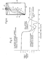
- Figure 5 is a graph showing the discharge curves for a cell utilising a lithium anode as illustrated in Figures 1 to 3 and for a cell utilising a prior art lithium anode; and
- Figure 6 is a sectional view similar to the view of Figure 2, but of a modified design.
- Referring to Figures 1 and 3, a
lithium anode 10 has inlaid into the lithium body acopper alloy strip 12 which is oxygen free and has high conductivity. The ratio of copper area to lithium area computed for the anode face to which the copper has been laminated is 0.'1. In order to minimise breakage of the copper anode strip during prolonged periods of forced discharge, the ratio of copper area to lithium area computed for the anode face to which the copper has been laminated should not be less than 0.075, and preferably is at least 0.1 when a flat or tape-like strip as shown in Figure 2 is employed. However, if the copper anode strip is in the form of a wire 12' as shown in Figure 6, the ratio of copper area to lithium area can be as low as 0.02. The ratio can be as large as 0.25 without detrimentally affecting the performance or the discharge characteristics of the lithium anode. - The
anode 10 includes, in addition tocopper alloy strip 12, aterminal tab 14 which can be of any highly conductive metal, but preferably is of copper. - The anode fabricated according to the present invention preferably is employed in a rolled lithium-sulphur dioxide cell as shown in Figure 4 wherein the components of the cell, i.e. the
anode 10,cathode 18 and adouble separator 16 between the anode and cathode are constructed as strips and the components then rolled for assembly into acell casing 20 having asafety vent 22. The gaseous sulphur dioxide electrolyte is injected into the cell casing after the components are in place. - The bottom of the
cell housing 24 forms the negative terminal of the cell, and acap 26 is inserted into the top of the cell which is the positive terminal. The components are suitably sealed, for example with a glass-metal seal 28, so as to prevent escape of the sulphur dioxide gas. As shown in Figure 4, theanode 10 in the form of a strip is separated from thecarbon cathode 18 by the two layers ofseparator 16. However, because of the rolled configuration of the anode and cathode, both faces of the lithium anode contact the carbon cathode through the separator, and, accordingly, in spite ofcopper strip 12, all of the lithium of the anode is available for consumption. This configuration, therefore, is ideally suited to provide a coulombic balance between the lithium of the cell and the sulphur dioxide electrolyte. The coulombic balance permits a total discharge and utilisation of the lithium during the life of the cell, providing not only economic utilisation of the anode materíis, but also prevents possible hazards when the cell is disposed of. - Figure 5 in chart form, sets forth the superior performance characteristics of a sulphur dioxide system in accordance with the invention when subjected to forced discharge. As seen from curve A, a cell utilising the lithium anode of the present invention, at a constant rate of 1 ampere, has excellent voltage stability and permits the cell to be forced into voltage reversal for prolonged periods of time without adverse effects. In contradistinction, a cell utilising a lithium anode without the copper strip of the present invention, when subjected to the same discharge characteristics, has erratic stability under forced discharge conditions which can result in bulging, venting and even possible cell rupture.
- Although it is not completely clear how the copper strip accomplishes the stated objectives, it appears, based on analysis of a discharged cell that the copper of the copper strip enters into a chemical and/or electro-chemical reaction with the chemical species released during the primary cell reaction under the forced discharge conditions. Qualitative analysis on discharged cells has evidenced the existence of electro-chemical reactions which have resulted in the deposition of copper into the pores of the carbonaceous cathode, thereby eliminating from further reaction the "free" chemical species for reactions which may provide cell bulging, venting or possible explosion.
Claims (6)
Applications Claiming Priority (4)
| Application Number | Priority Date | Filing Date | Title |
|---|---|---|---|
| US43069182A | 1982-09-30 | 1982-09-30 | |
| US430691 | 1982-09-30 | ||
| US518035 | 1983-08-01 | ||
| US06/518,035 US4482615A (en) | 1982-09-30 | 1983-08-01 | Lithium anode comprising copper strip in contact with lithium body and lithium-sulfur dioxide battery utilizing same |
Publications (3)
| Publication Number | Publication Date |
|---|---|
| EP0106602A2 true EP0106602A2 (en) | 1984-04-25 |
| EP0106602A3 EP0106602A3 (en) | 1984-11-07 |
| EP0106602B1 EP0106602B1 (en) | 1987-12-09 |
Family
ID=27028704
Family Applications (1)
| Application Number | Title | Priority Date | Filing Date |
|---|---|---|---|
| EP83305883A Expired EP0106602B1 (en) | 1982-09-30 | 1983-09-29 | Lithium-sulphur dioxide cell and electrode therefor |
Country Status (4)
| Country | Link |
|---|---|
| US (1) | US4482615A (en) |
| EP (1) | EP0106602B1 (en) |
| CA (1) | CA1199678A (en) |
| DE (1) | DE3374910D1 (en) |
Cited By (1)
| Publication number | Priority date | Publication date | Assignee | Title |
|---|---|---|---|---|
| FR2935544A1 (en) * | 2008-08-29 | 2010-03-05 | Saft Groupe Sa | CURRENT COLLECTOR FOR ANODE OF LITHIUM PRIMARY ELECTROCHEMICAL GENERATOR |
Families Citing this family (26)
| Publication number | Priority date | Publication date | Assignee | Title |
|---|---|---|---|---|
| US4622277A (en) * | 1985-09-30 | 1986-11-11 | Duracell Inc. | Electrochemical cells |
| US4937154A (en) * | 1988-11-16 | 1990-06-26 | Duracell Inc. | Electrochemical cell |
| US5368958A (en) * | 1992-08-20 | 1994-11-29 | Advanced Energy Technologies Incorporated | Lithium anode with conductive for and anode tab for rechargeable lithium battery |
| US5458993A (en) * | 1993-11-22 | 1995-10-17 | Matsushita Electric Industrial Co., Ltd. | Non-aqueous electrolyte battery and method of manufacturing same |
| JP3373934B2 (en) * | 1994-05-25 | 2003-02-04 | 三洋電機株式会社 | Non-aqueous electrolyte battery with spiral electrode body |
| US6849360B2 (en) | 2002-06-05 | 2005-02-01 | Eveready Battery Company, Inc. | Nonaqueous electrochemical cell with improved energy density |
| US20050196667A1 (en) * | 2004-03-03 | 2005-09-08 | Eaglepicher Technologies, Llc | Anode design for a prismatically wound LiMnO2 cell |
| US7614907B2 (en) * | 2008-02-12 | 2009-11-10 | Chaojiong Zhang | Contact terminal with self-adjusting contact surface |
| US8119286B2 (en) * | 2009-11-24 | 2012-02-21 | The Gillette Company | Electrochemical cells with improved separator and electrolyte |
| US11081721B2 (en) | 2009-11-24 | 2021-08-03 | Duracell U.S. Operations, Inc. | Secondary electrochemical cells with separator and electrolyte combination |
| US8349493B2 (en) * | 2009-11-24 | 2013-01-08 | The Gillette Company | Electrochemical cells with improved separator and electrolyte |
| US8920969B2 (en) | 2012-12-05 | 2014-12-30 | The Gillette Company | Alkaline electrochemical cells with separator and electrolyte combination |
| US10008748B2 (en) | 2012-12-05 | 2018-06-26 | Duracell U.S. Operations, Inc. | Alkaline electrochemical cells with separator and electrolyte combination |
| US9551758B2 (en) | 2012-12-27 | 2017-01-24 | Duracell U.S. Operations, Inc. | Remote sensing of remaining battery capacity using on-battery circuitry |
| US9478850B2 (en) | 2013-05-23 | 2016-10-25 | Duracell U.S. Operations, Inc. | Omni-directional antenna for a cylindrical body |
| US9726763B2 (en) | 2013-06-21 | 2017-08-08 | Duracell U.S. Operations, Inc. | Systems and methods for remotely determining a battery characteristic |
| US9882250B2 (en) | 2014-05-30 | 2018-01-30 | Duracell U.S. Operations, Inc. | Indicator circuit decoupled from a ground plane |
| CN107925052A (en) | 2015-06-22 | 2018-04-17 | 阿卜杜拉国王科技大学 | The manufacture method of lithium battery, anode and anode |
| US10297875B2 (en) | 2015-09-01 | 2019-05-21 | Duracell U.S. Operations, Inc. | Battery including an on-cell indicator |
| US10151802B2 (en) | 2016-11-01 | 2018-12-11 | Duracell U.S. Operations, Inc. | Reusable battery indicator with electrical lock and key |
| US10608293B2 (en) | 2016-11-01 | 2020-03-31 | Duracell U.S. Operations, Inc. | Dual sided reusable battery indicator |
| US11024891B2 (en) | 2016-11-01 | 2021-06-01 | Duracell U.S. Operations, Inc. | Reusable battery indicator with lock and key mechanism |
| US10818979B2 (en) | 2016-11-01 | 2020-10-27 | Duracell U.S. Operations, Inc. | Single sided reusable battery indicator |
| US10483634B2 (en) | 2016-11-01 | 2019-11-19 | Duracell U.S. Operations, Inc. | Positive battery terminal antenna ground plane |
| US11217846B2 (en) | 2017-03-16 | 2022-01-04 | Eaglepicher Technologies, Llc | Electrochemical cell |
| US11837754B2 (en) | 2020-12-30 | 2023-12-05 | Duracell U.S. Operations, Inc. | Magnetic battery cell connection mechanism |
Family Cites Families (6)
| Publication number | Priority date | Publication date | Assignee | Title |
|---|---|---|---|---|
| US3939011A (en) * | 1973-01-05 | 1976-02-17 | P. R. Mallory & Co. Inc. | Lithium cell with internal automatic safety controls |
| US4168351A (en) * | 1978-02-10 | 1979-09-18 | P. R. Mallory & Co., Inc. | Stabilized glass-to-metal seals in lithium cell environments |
| US4184012A (en) * | 1978-06-05 | 1980-01-15 | P. R. Mallory & Co. Inc. | Cell reaction barrier |
| US4385101A (en) * | 1980-04-28 | 1983-05-24 | Catanzarite Vincent Owen | Electrochemical cell structure |
| US4335191A (en) * | 1980-07-28 | 1982-06-15 | Tadiran Israel Electronics Industries Ltd. | Lithium cells |
| US4450213A (en) * | 1982-01-18 | 1984-05-22 | Duracell Inc. | Cell having improved abuse resistance |
-
1983
- 1983-08-01 US US06/518,035 patent/US4482615A/en not_active Expired - Lifetime
- 1983-09-26 CA CA000437582A patent/CA1199678A/en not_active Expired
- 1983-09-29 EP EP83305883A patent/EP0106602B1/en not_active Expired
- 1983-09-29 DE DE8383305883T patent/DE3374910D1/en not_active Expired
Cited By (1)
| Publication number | Priority date | Publication date | Assignee | Title |
|---|---|---|---|---|
| FR2935544A1 (en) * | 2008-08-29 | 2010-03-05 | Saft Groupe Sa | CURRENT COLLECTOR FOR ANODE OF LITHIUM PRIMARY ELECTROCHEMICAL GENERATOR |
Also Published As
| Publication number | Publication date |
|---|---|
| EP0106602A3 (en) | 1984-11-07 |
| EP0106602B1 (en) | 1987-12-09 |
| US4482615A (en) | 1984-11-13 |
| DE3374910D1 (en) | 1988-01-21 |
| CA1199678A (en) | 1986-01-21 |
Similar Documents
| Publication | Publication Date | Title |
|---|---|---|
| EP0106602B1 (en) | Lithium-sulphur dioxide cell and electrode therefor | |
| US4318969A (en) | Electrochemical cell | |
| US4942101A (en) | Electrochemical cell having an alkaline electrolyte and a zinc negative electrode | |
| EP0150054B1 (en) | Flat cell | |
| DE69524894D1 (en) | Prismatic high performance cell | |
| CA1141429A (en) | Abuse resistant active metal anode/fluid cathode depolarized cells | |
| GB2187590A (en) | Electrochemical cells | |
| JPH07302597A (en) | Lithium battery | |
| US4939048A (en) | Electrochemical cell having an alkaline electrolyte and a zinc negative electrode | |
| US3982958A (en) | Non-aqueous battery system | |
| US2582973A (en) | Sealing means for primary alkaline dry cells | |
| US5639578A (en) | Current collectors for alkaline cells | |
| EP0617845A1 (en) | Cathodes for zinc manganese dioxide cells having barium additives. | |
| CA1232634A (en) | Battery cell | |
| US5213914A (en) | Non-aqueous, rechargeable electrochemical cell | |
| Sarakonsri et al. | Primary batteries | |
| US2572017A (en) | Dry battery cell | |
| US3342639A (en) | Sealed alkaline cells and electrolytes therefor | |
| US4371592A (en) | Primary cell of high energy density in which the anode active material is an alkali metal | |
| EP0567506B1 (en) | Improvements to high temperature secondary batteries | |
| US3236690A (en) | Rechargeable alkaline cell and liquid phase-containing amalgam anode therefor | |
| EP1293002B1 (en) | Electrochemical cells with an anode containing sulfur | |
| US4581305A (en) | Electrochemical cell | |
| CA1236159A (en) | Organic siliconate additive for alkaline zinc electrochemical cells | |
| JPH0438102B2 (en) |
Legal Events
| Date | Code | Title | Description |
|---|---|---|---|
| PUAI | Public reference made under article 153(3) epc to a published international application that has entered the european phase |
Free format text: ORIGINAL CODE: 0009012 |
|
| AK | Designated contracting states |
Designated state(s): DE FR GB |
|
| PUAL | Search report despatched |
Free format text: ORIGINAL CODE: 0009013 |
|
| AK | Designated contracting states |
Designated state(s): DE FR GB |
|
| 17P | Request for examination filed |
Effective date: 19850401 |
|
| 17Q | First examination report despatched |
Effective date: 19860213 |
|
| GRAA | (expected) grant |
Free format text: ORIGINAL CODE: 0009210 |
|
| AK | Designated contracting states |
Kind code of ref document: B1 Designated state(s): DE FR GB |
|
| REF | Corresponds to: |
Ref document number: 3374910 Country of ref document: DE Date of ref document: 19880121 |
|
| ET | Fr: translation filed | ||
| PLBE | No opposition filed within time limit |
Free format text: ORIGINAL CODE: 0009261 |
|
| STAA | Information on the status of an ep patent application or granted ep patent |
Free format text: STATUS: NO OPPOSITION FILED WITHIN TIME LIMIT |
|
| 26N | No opposition filed | ||
| REG | Reference to a national code |
Ref country code: GB Ref legal event code: IF02 |
|
| PGFP | Annual fee paid to national office [announced via postgrant information from national office to epo] |
Ref country code: GB Payment date: 20020925 Year of fee payment: 20 |
|
| PGFP | Annual fee paid to national office [announced via postgrant information from national office to epo] |
Ref country code: DE Payment date: 20021002 Year of fee payment: 20 |
|
| PGFP | Annual fee paid to national office [announced via postgrant information from national office to epo] |
Ref country code: FR Payment date: 20021008 Year of fee payment: 20 |
|
| PG25 | Lapsed in a contracting state [announced via postgrant information from national office to epo] |
Ref country code: GB Free format text: LAPSE BECAUSE OF EXPIRATION OF PROTECTION Effective date: 20030928 |
|
| REG | Reference to a national code |
Ref country code: GB Ref legal event code: PE20 |