EP0106048B1 - Casing hanger collet - Google Patents
Casing hanger collet Download PDFInfo
- Publication number
- EP0106048B1 EP0106048B1 EP83107767A EP83107767A EP0106048B1 EP 0106048 B1 EP0106048 B1 EP 0106048B1 EP 83107767 A EP83107767 A EP 83107767A EP 83107767 A EP83107767 A EP 83107767A EP 0106048 B1 EP0106048 B1 EP 0106048B1
- Authority
- EP
- European Patent Office
- Prior art keywords
- legs
- collet
- segments
- slots
- casing
- Prior art date
- Legal status (The legal status is an assumption and is not a legal conclusion. Google has not performed a legal analysis and makes no representation as to the accuracy of the status listed.)
- Expired
Links
- 239000012530 fluid Substances 0.000 claims 1
- 238000005553 drilling Methods 0.000 description 4
- 239000000725 suspension Substances 0.000 description 4
- 229910000831 Steel Inorganic materials 0.000 description 3
- 239000010959 steel Substances 0.000 description 3
- 229910000851 Alloy steel Inorganic materials 0.000 description 1
- 241000282472 Canis lupus familiaris Species 0.000 description 1
- 229910045601 alloy Inorganic materials 0.000 description 1
- 239000000956 alloy Substances 0.000 description 1
- 238000005452 bending Methods 0.000 description 1
- 150000001875 compounds Chemical class 0.000 description 1
- 230000003247 decreasing effect Effects 0.000 description 1
- 230000001419 dependent effect Effects 0.000 description 1
- 238000003754 machining Methods 0.000 description 1
- 238000004519 manufacturing process Methods 0.000 description 1
- 239000000463 material Substances 0.000 description 1
- 238000003801 milling Methods 0.000 description 1
- 230000000644 propagated effect Effects 0.000 description 1
- 238000005096 rolling process Methods 0.000 description 1
Images

Classifications
-
- E—FIXED CONSTRUCTIONS
- E21—EARTH OR ROCK DRILLING; MINING
- E21B—EARTH OR ROCK DRILLING; OBTAINING OIL, GAS, WATER, SOLUBLE OR MELTABLE MATERIALS OR A SLURRY OF MINERALS FROM WELLS
- E21B33/00—Sealing or packing boreholes or wells
- E21B33/02—Surface sealing or packing
- E21B33/03—Well heads; Setting-up thereof
- E21B33/04—Casing heads; Suspending casings or tubings in well heads
- E21B33/043—Casing heads; Suspending casings or tubings in well heads specially adapted for underwater well heads
Definitions
- the invention relates to casing hangers and in particular to a support collet for mudline-type hangers.
- Mudline suspension systems are used to provide a means to hang off well bore casing strings below the ocean mudline during drilling. This avoids a need to build an offshore structure to accept the string weights and permits one to abandon the well temporarily until area exploration or all drilling of that location is completed.
- Prior art hangers have used locking rings. These rings are secured to the inner casing and are continuously urged outwardly. They collapse sufficiently to pass through the casing bore and include latches on the rings which are formed to match receiving grooves in the outer casing at the support elevation. Releasable retaining means such as shear pins are sheared by the weight of the casing when the latches lock into the grooves. The inner casing is then lowered so that its shoulder rests on the ring.
- One form of prior art ring illustrated in US-A-3,893,717 is a C-shape with a section necessarily removed to allow it to collapse circumferentially to a point that it will pass through the bore of the casing used above the hanger housing in the preceding string.
- the C-shape ring requires a substantial wall section to provide a load carrying area for the "ring to housing" interface (seat) and also a load carrying area for the ring to hanger support, (top of the C-shape ring). Being that the hanger body must be able to drift through the casing, these load carrying areas must be in two distinct radial planes.
- Still another form shown in US-A-4,139,059 uses fingers which are cantilevered upwardly from a lower ring.
- hanger collet for a mudline suspension system is of a single piece in the form of a hollow cylinder.
- Vertical legs of the cylinder are formed by a plurality of part-length vertical slots alternating from the top and bottom and overlapping.
- Upper and lower return segments join adjacent legs.
- Latch means are located on the upper segments, extending outwardly for engagement with the outer casing.
- the object of the invention is to improve the circulation when using in well drilling a hanger collet of the type described in the preamble of claim 10.
- the vertical legs have flow space behind them so that flow passing into the bottom opening slots may pass to and through the upper slots during cementing, thereby passing by the hanger.
- a minimum amount of the load bearing portion must be removed, since all of the slots cooperate to allow the reduced diameter. All the slots are the equivalent of the removed section of a C-ring, and additional material removal is not required.
- the segments move radially in and out without any circumferential motion.
- the collet may be designed for low stress during collapse, precluding the need for high tensile steel.
- the hanger collet 10 is illustrated in Figure 1 in place and carrying an inner casing from an outer casing.
- the outer casing includes a hanger body 12 which has annular grooves 14 and 16.
- the collet is urged outwardly so that when it reaches the location where it may mate with the annular grooves, it springs outwardly into the position shown.
- the load from the inner casing 18 with its hanger body 44 passes through the upper support shoulder 20 of the collet and then through the latching means 22 to the outer casing 12.
- Figure 1 illustrates the hanger collet 10 as a hollow cylinder of low alloy steel.
- the collet is about 21.6 cm (8 and 1/2 inch) ID and 38.1 cm (15 inches) high.
- Vertical legs 30 are formed between part-length slots 32 from the top and 34 from the bottom.
- Upper return segments 36 join adjacent legs and carry latch means 22 extending outwardly therefrom.
- Lower return segments 40 join adjacent legs so that a sinuous pattern is formed of the legs.
- the collet must be collapsed when running the hanger so that the collet fits within the inside diameter of the outer casing 12. As the collet is squeezed down, the open ends of the slots close with bending occurring in the legs 30 and in the return segments 36 and 40. The legs tend to take an S-shape while the return bends at the segments exert a force tending to open the slots. This creates a force returning the collet to its full uncollapsed size. The length, size and number of the legs may be varied to achieve the desired stiffness of the collet.
- the collet is strain limited during collapse, rather than load limited. Accordingly, the collet may be made as soft as desired with an increased number of slots, decreased thickness of legs, and/ or increased length. Maximum stress is expected at the crotch of the segments in a very localized manner. Because of the substantial remaining portion of each segment, even permanent deformation of the high stress area would not prevent full expansion of the released collet. The lack of need for high tensile strength steel, permits the use of lower alloy steels less susceptible to stress propagated failures.
- the outer surface 42 of the legs 30 extends outwardly the same distance as the latching means 22. Accordingly, this surface along with the latching means forms a key, whereby the collet can expand during the running operation only when both latches and the legs key with matching grooves in the outer casing. Since the compressed collet takes a barrel shape, rubbing during running takes place primarily on the. legs.
- the collet 10 as shown in Figure 1 will usually be locked in place with a back up member such as casing hanger body 44.
- Legs 30 are formed with an inner surface 46 being of a larger diameter than the inner surface 48 of the segments 36. This provides a flowpath during the cementing operation upwards through slot 34, behind the legs 30 to slot 32, and then upwardly between segments 36.
- Each lower segment 40 has a hole 50 for receiving a shear pin. This provides a means for releasably attaching the collet to the inner casing for pulling the collet downwardly before it latches into place.
- the collet is easily manufactured to precise tolerances by first machining the inner and outer surfaces and then milling the slots.
- Both top and bottom segments move radially in and out resulting in freedom from any circumferential component of motion during collapse and expansion. This permits a cleaner shear or latch action on any holddown linkage. This also avoids a rolling under action which can occur at the edge of a C-shaped member when it is collapsed. If one segment is blocked from latching, it will not restrain latching of adjacent segments and will increase the force tending to latch the other segments.
Landscapes
- Life Sciences & Earth Sciences (AREA)
- Engineering & Computer Science (AREA)
- Geology (AREA)
- Mining & Mineral Resources (AREA)
- Physics & Mathematics (AREA)
- Environmental & Geological Engineering (AREA)
- Fluid Mechanics (AREA)
- General Life Sciences & Earth Sciences (AREA)
- Geochemistry & Mineralogy (AREA)
- Earth Drilling (AREA)
- Vehicle Body Suspensions (AREA)
- Centrifugal Separators (AREA)
Description
- The invention relates to casing hangers and in particular to a support collet for mudline-type hangers.
- Mudline suspension systems are used to provide a means to hang off well bore casing strings below the ocean mudline during drilling. This avoids a need to build an offshore structure to accept the string weights and permits one to abandon the well temporarily until area exploration or all drilling of that location is completed.
- As drilling in offshore applications tends toward deeper production zones, the casing hangers must carry additional weight. Deeper holes require more and longer strings to complete the well. Increasing wall sections to deal with the higher pressure compound suspension problems with heavier string weights and reduced annular area to work in. The annular area must be effectively divided between suspension and circulation (for cementing purposes) requirements.
- Prior art hangers have used locking rings. These rings are secured to the inner casing and are continuously urged outwardly. They collapse sufficiently to pass through the casing bore and include latches on the rings which are formed to match receiving grooves in the outer casing at the support elevation. Releasable retaining means such as shear pins are sheared by the weight of the casing when the latches lock into the grooves. The inner casing is then lowered so that its shoulder rests on the ring.
- One form of prior art ring illustrated in US-A-3,893,717 is a C-shape with a section necessarily removed to allow it to collapse circumferentially to a point that it will pass through the bore of the casing used above the hanger housing in the preceding string. The C-shape ring requires a substantial wall section to provide a load carrying area for the "ring to housing" interface (seat) and also a load carrying area for the ring to hanger support, (top of the C-shape ring). Being that the hanger body must be able to drift through the casing, these load carrying areas must be in two distinct radial planes.
- To increase flexibility of the C-shape ring and avoid permanent deformation, additional parts of the wall section at selected points around the circumference must be removed. This removes bearing surface, in addition to that removed to permit collapse.
- Another form also shown in US-A-3,893,717 uses separate dogs urged outwardly by an internal C-member.
- Still another form shown in US-A-4,139,059 uses fingers which are cantilevered upwardly from a lower ring.
- An additional form of a prior art hanger collet of the type referred to in the preamble of claim 1 is disclosed in WO-A-82/01393, wherein the hanger collet for a mudline suspension system is of a single piece in the form of a hollow cylinder. Vertical legs of the cylinder are formed by a plurality of part-length vertical slots alternating from the top and bottom and overlapping. Upper and lower return segments join adjacent legs. Latch means are located on the upper segments, extending outwardly for engagement with the outer casing.
- The object of the invention is to improve the circulation when using in well drilling a hanger collet of the type described in the preamble of
claim 10. - This object is achieved by the features claimed in the characterizing part of claim 1. Advantageous embodiments of the invention are claimed in the dependent claims.
- The vertical legs have flow space behind them so that flow passing into the bottom opening slots may pass to and through the upper slots during cementing, thereby passing by the hanger. A minimum amount of the load bearing portion must be removed, since all of the slots cooperate to allow the reduced diameter. All the slots are the equivalent of the removed section of a C-ring, and additional material removal is not required. The segments move radially in and out without any circumferential motion. The collet may be designed for low stress during collapse, precluding the need for high tensile steel.
- The invention will now be described by way of example with reference to the accompanying drawings, wherein:
- Figure 1 is a sectional view assembly drawing showing the priort art collet in use;
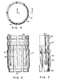
- Figure 2 is a side elevation of the collet as modified in accordance with the invention;
- Figure 3 is a section of the collect of Figure 2 through an upper slot showing the structure of an individual leg; and
- Figure 4 is a plan view of the collet of the invention.
- The
hanger collet 10 is illustrated in Figure 1 in place and carrying an inner casing from an outer casing. The outer casing includes ahanger body 12 which hasannular grooves - The collet is urged outwardly so that when it reaches the location where it may mate with the annular grooves, it springs outwardly into the position shown. The load from the
inner casing 18 with its hanger body 44 passes through theupper support shoulder 20 of the collet and then through the latching means 22 to theouter casing 12. - Figure 1 illustrates the
hanger collet 10 as a hollow cylinder of low alloy steel. The collet is about 21.6 cm (8 and 1/2 inch) ID and 38.1 cm (15 inches) high.Vertical legs 30 are formed between part-length slots 32 from the top and 34 from the bottom. -
Upper return segments 36 join adjacent legs and carry latch means 22 extending outwardly therefrom.Lower return segments 40 join adjacent legs so that a sinuous pattern is formed of the legs. - The collet must be collapsed when running the hanger so that the collet fits within the inside diameter of the
outer casing 12. As the collet is squeezed down, the open ends of the slots close with bending occurring in thelegs 30 and in thereturn segments - The collet is strain limited during collapse, rather than load limited. Accordingly, the collet may be made as soft as desired with an increased number of slots, decreased thickness of legs, and/ or increased length. Maximum stress is expected at the crotch of the segments in a very localized manner. Because of the substantial remaining portion of each segment, even permanent deformation of the high stress area would not prevent full expansion of the released collet. The lack of need for high tensile strength steel, permits the use of lower alloy steels less susceptible to stress propagated failures.
- The
outer surface 42 of thelegs 30 extends outwardly the same distance as the latching means 22. Accordingly, this surface along with the latching means forms a key, whereby the collet can expand during the running operation only when both latches and the legs key with matching grooves in the outer casing. Since the compressed collet takes a barrel shape, rubbing during running takes place primarily on the. legs. - In its latched position the
collet 10 as shown in Figure 1 will usually be locked in place with a back up member such as casing hanger body 44.Legs 30 are formed with aninner surface 46 being of a larger diameter than theinner surface 48 of thesegments 36. This provides a flowpath during the cementing operation upwards throughslot 34, behind thelegs 30 toslot 32, and then upwardly betweensegments 36. Eachlower segment 40 has ahole 50 for receiving a shear pin. This provides a means for releasably attaching the collet to the inner casing for pulling the collet downwardly before it latches into place. - The collet is easily manufactured to precise tolerances by first machining the inner and outer surfaces and then milling the slots.
- Both top and bottom segments move radially in and out resulting in freedom from any circumferential component of motion during collapse and expansion. This permits a cleaner shear or latch action on any holddown linkage. This also avoids a rolling under action which can occur at the edge of a C-shaped member when it is collapsed. If one segment is blocked from latching, it will not restrain latching of adjacent segments and will increase the force tending to latch the other segments.
Claims (4)
Applications Claiming Priority (3)
| Application Number | Priority Date | Filing Date | Title |
|---|---|---|---|
| US06/418,503 US4465133A (en) | 1982-09-15 | 1982-09-15 | Casing hanger collet |
| AU20485/83A AU2048583A (en) | 1982-09-15 | 1983-10-21 | Casing hanger collet |
| US418503 | 1995-04-07 |
Publications (3)
| Publication Number | Publication Date |
|---|---|
| EP0106048A2 EP0106048A2 (en) | 1984-04-25 |
| EP0106048A3 EP0106048A3 (en) | 1985-07-31 |
| EP0106048B1 true EP0106048B1 (en) | 1988-05-11 |
Family
ID=25617900
Family Applications (1)
| Application Number | Title | Priority Date | Filing Date |
|---|---|---|---|
| EP83107767A Expired EP0106048B1 (en) | 1982-09-15 | 1983-08-06 | Casing hanger collet |
Country Status (9)
| Country | Link |
|---|---|
| US (1) | US4465133A (en) |
| EP (1) | EP0106048B1 (en) |
| JP (1) | JPS5972393A (en) |
| AU (1) | AU2048583A (en) |
| BR (1) | BR8304955A (en) |
| CA (1) | CA1192131A (en) |
| DE (1) | DE3376577D1 (en) |
| DK (1) | DK418383A (en) |
| NO (1) | NO168599C (en) |
Families Citing this family (13)
| Publication number | Priority date | Publication date | Assignee | Title |
|---|---|---|---|---|
| US4691780A (en) * | 1985-06-03 | 1987-09-08 | Cameron Iron Works, Inc. | Subsea wellhead structure |
| US4826216A (en) * | 1988-04-28 | 1989-05-02 | Cameron Iron Works Usa, Inc. | Well housing and landing shoulder |
| US5026097A (en) * | 1989-07-28 | 1991-06-25 | Dril-Quip, Inc. | Wellhead apparatus |
| US4969517A (en) * | 1989-08-25 | 1990-11-13 | Fmc Corporation | Sub-mudling casing hanger/packoff |
| US5222555A (en) * | 1991-12-13 | 1993-06-29 | Abb Vetco Gray Inc. | Emergency casing hanger system |
| US5267612A (en) * | 1992-04-06 | 1993-12-07 | Cassin Allen E | Friction plug for a high pressure pipe |
| US5421623A (en) * | 1994-05-26 | 1995-06-06 | Cassin; Allen E. | Friction sealed coupling for pipe |
| GB2332256B (en) * | 1997-12-05 | 2002-01-16 | Britannia Engineering Consulta | Tubular connection |
| US7404445B2 (en) * | 2004-05-20 | 2008-07-29 | Baker Hughes Incorporated | Perimetrically loading collet |
| JP5043349B2 (en) * | 2006-03-15 | 2012-10-10 | 三菱レイヨン株式会社 | Acid-resistant fixed seal joint |
| US12448857B2 (en) | 2022-10-07 | 2025-10-21 | Halliburton Energy Services, Inc. | Latch coupling including unique axial alignment slots |
| US12448848B2 (en) | 2022-10-07 | 2025-10-21 | Halliburton Energy Services, Inc. | Downhole tool including a packer assembly, a completion assembly, and a removably coupled whipstock assembly |
| WO2025208221A1 (en) * | 2024-04-04 | 2025-10-09 | Interra Energy Services Ltd. | Sleeve assemblies with split ring and related methods |
Family Cites Families (9)
| Publication number | Priority date | Publication date | Assignee | Title |
|---|---|---|---|---|
| US3179448A (en) * | 1962-03-13 | 1965-04-20 | Cameron Iron Works Inc | Wellhead apparatus |
| US3265409A (en) * | 1962-11-15 | 1966-08-09 | Gray Tool Co | Well completion equipment |
| US3420308A (en) * | 1967-08-16 | 1969-01-07 | Fmc Corp | Well casing hanger |
| US3893717A (en) * | 1974-05-15 | 1975-07-08 | Putch Samuel W | Well casing hanger assembly |
| US4116277A (en) * | 1977-04-12 | 1978-09-26 | Gray Tool Company | Full flow tubing plug with locked anchor and method |
| US4139059A (en) * | 1977-12-12 | 1979-02-13 | W-K-M Wellhead Systems, Inc. | Well casing hanger assembly |
| US4167970A (en) * | 1978-06-16 | 1979-09-18 | Armco Inc. | Hanger apparatus for suspending pipes |
| US4307902A (en) * | 1979-07-13 | 1981-12-29 | Otis Engineering Corp. | Riser connector |
| US4355825A (en) * | 1980-10-15 | 1982-10-26 | Cameron Iron Works, Inc. | Mudline suspension system |
-
1982
- 1982-09-15 US US06/418,503 patent/US4465133A/en not_active Expired - Lifetime
-
1983
- 1983-08-02 NO NO832787A patent/NO168599C/en not_active IP Right Cessation
- 1983-08-06 EP EP83107767A patent/EP0106048B1/en not_active Expired
- 1983-08-06 DE DE8383107767T patent/DE3376577D1/en not_active Expired
- 1983-08-10 CA CA000434332A patent/CA1192131A/en not_active Expired
- 1983-09-13 BR BR8304955A patent/BR8304955A/en not_active IP Right Cessation
- 1983-09-14 DK DK418383A patent/DK418383A/en not_active Application Discontinuation
- 1983-09-14 JP JP58168522A patent/JPS5972393A/en active Pending
- 1983-10-21 AU AU20485/83A patent/AU2048583A/en not_active Abandoned
Also Published As
| Publication number | Publication date |
|---|---|
| NO832787L (en) | 1984-03-16 |
| US4465133A (en) | 1984-08-14 |
| BR8304955A (en) | 1984-04-24 |
| CA1192131A (en) | 1985-08-20 |
| DK418383D0 (en) | 1983-09-14 |
| DE3376577D1 (en) | 1988-06-16 |
| NO168599B (en) | 1991-12-02 |
| JPS5972393A (en) | 1984-04-24 |
| NO168599C (en) | 1992-03-11 |
| AU2048583A (en) | 1984-05-03 |
| DK418383A (en) | 1984-03-16 |
| EP0106048A3 (en) | 1985-07-31 |
| EP0106048A2 (en) | 1984-04-25 |
Similar Documents
| Publication | Publication Date | Title |
|---|---|---|
| US4465133A (en) | Casing hanger collet | |
| US5526888A (en) | Apparatus for axial connection and joinder of tubulars by application of remote hydraulic pressure | |
| CA1282688C (en) | Well suspension assembly | |
| US5307879A (en) | Positive lockdown for metal seal | |
| EP0289107B1 (en) | Wellhead seal assembly | |
| US5066048A (en) | Weight set connecting mechanism for subsea tubular members | |
| US4497592A (en) | Self-levelling underwater structure | |
| CA2059115C (en) | Supported-lip low interference metal stab seal | |
| US3297344A (en) | Connectors for well parts | |
| EP0417365B1 (en) | Marine casing suspension apparatus | |
| WO1998022690A1 (en) | Connector for an expandable tubing string | |
| CA2067061A1 (en) | Centralizer for centring drilling and casing pipes and centralizing arrangement including said centralizer | |
| EP1404945B1 (en) | Expandable wellbore stabiliser | |
| US20150114667A1 (en) | High Strength Inlay to Improve Lock-Down Capacity in a Wellhead | |
| US11713639B2 (en) | Pressure energized seal with groove profile | |
| US6516875B2 (en) | Tubing hanger lockdown mechanism | |
| BR102012013611A2 (en) | WELL HEAD ASSEMBLY AND METHOD FOR INSTALLING A HOOK IN AN UNDERWATER HEAD HOSTING ASSEMBLY | |
| EP3365526B1 (en) | Wellhead seal assembly with lockdown and slotted arrangement | |
| EP0552525A1 (en) | Hanger assembly | |
| CA1242972A (en) | Slip and slip assembly for well tools | |
| US8562028B2 (en) | Connector assembly | |
| EP0592739B1 (en) | Load support ring | |
| US4886113A (en) | Positive indication shear ring | |
| GB2060030A (en) | Well casing hanger assembly | |
| US4515400A (en) | Wellhead assembly |
Legal Events
| Date | Code | Title | Description |
|---|---|---|---|
| PUAI | Public reference made under article 153(3) epc to a published international application that has entered the european phase |
Free format text: ORIGINAL CODE: 0009012 |
|
| AK | Designated contracting states |
Designated state(s): DE FR GB IT NL |
|
| RAP1 | Party data changed (applicant data changed or rights of an application transferred) |
Owner name: COMBUSTION ENGINEERING, INC. |
|
| PUAL | Search report despatched |
Free format text: ORIGINAL CODE: 0009013 |
|
| AK | Designated contracting states |
Designated state(s): DE FR GB IT NL |
|
| 17P | Request for examination filed |
Effective date: 19860128 |
|
| RAP1 | Party data changed (applicant data changed or rights of an application transferred) |
Owner name: GRAY TOOL COMPANY |
|
| 17Q | First examination report despatched |
Effective date: 19870122 |
|
| RAP1 | Party data changed (applicant data changed or rights of an application transferred) |
Owner name: VETCO GRAY INC. |
|
| GRAA | (expected) grant |
Free format text: ORIGINAL CODE: 0009210 |
|
| AK | Designated contracting states |
Kind code of ref document: B1 Designated state(s): DE FR GB IT NL |
|
| PG25 | Lapsed in a contracting state [announced via postgrant information from national office to epo] |
Ref country code: NL Effective date: 19880511 Ref country code: IT Free format text: LAPSE BECAUSE OF FAILURE TO SUBMIT A TRANSLATION OF THE DESCRIPTION OR TO PAY THE FEE WITHIN THE PRESCRIBED TIME-LIMIT;WARNING: LAPSES OF ITALIAN PATENTS WITH EFFECTIVE DATE BEFORE 2007 MAY HAVE OCCURRED AT ANY TIME BEFORE 2007. THE CORRECT EFFECTIVE DATE MAY BE DIFFERENT FROM THE ONE RECORDED. Effective date: 19880511 |
|
| REF | Corresponds to: |
Ref document number: 3376577 Country of ref document: DE Date of ref document: 19880616 |
|
| ET | Fr: translation filed | ||
| PG25 | Lapsed in a contracting state [announced via postgrant information from national office to epo] |
Ref country code: DE Effective date: 19880622 |
|
| NLV1 | Nl: lapsed or annulled due to failure to fulfill the requirements of art. 29p and 29m of the patents act | ||
| PLBE | No opposition filed within time limit |
Free format text: ORIGINAL CODE: 0009261 |
|
| STAA | Information on the status of an ep patent application or granted ep patent |
Free format text: STATUS: NO OPPOSITION FILED WITHIN TIME LIMIT |
|
| 26N | No opposition filed | ||
| PGFP | Annual fee paid to national office [announced via postgrant information from national office to epo] |
Ref country code: GB Payment date: 19890731 Year of fee payment: 7 |
|
| PG25 | Lapsed in a contracting state [announced via postgrant information from national office to epo] |
Ref country code: GB Effective date: 19900806 |
|
| GBPC | Gb: european patent ceased through non-payment of renewal fee | ||
| PGFP | Annual fee paid to national office [announced via postgrant information from national office to epo] |
Ref country code: FR Payment date: 19940711 Year of fee payment: 12 |
|
| PG25 | Lapsed in a contracting state [announced via postgrant information from national office to epo] |
Ref country code: FR Effective date: 19960430 |
|
| REG | Reference to a national code |
Ref country code: FR Ref legal event code: ST |