EP0105801A2 - Well logging apparatus and method using transverse magnetic mode - Google Patents
Well logging apparatus and method using transverse magnetic mode Download PDFInfo
- Publication number
- EP0105801A2 EP0105801A2 EP83401907A EP83401907A EP0105801A2 EP 0105801 A2 EP0105801 A2 EP 0105801A2 EP 83401907 A EP83401907 A EP 83401907A EP 83401907 A EP83401907 A EP 83401907A EP 0105801 A2 EP0105801 A2 EP 0105801A2
- Authority
- EP
- European Patent Office
- Prior art keywords
- borehole
- transverse magnetic
- receiving
- electromagnetic energy
- logging
- Prior art date
- Legal status (The legal status is an assumption and is not a legal conclusion. Google has not performed a legal analysis and makes no representation as to the accuracy of the status listed.)
- Granted
Links
- 238000000034 method Methods 0.000 title claims abstract description 30
- 230000015572 biosynthetic process Effects 0.000 claims abstract description 35
- 238000005755 formation reaction Methods 0.000 claims abstract description 35
- 238000005553 drilling Methods 0.000 claims abstract description 21
- 238000005259 measurement Methods 0.000 abstract description 11
- 239000004020 conductor Substances 0.000 abstract description 4
- 239000012530 fluid Substances 0.000 description 13
- 239000002184 metal Substances 0.000 description 10
- 238000010586 diagram Methods 0.000 description 5
- 230000005540 biological transmission Effects 0.000 description 4
- 229910003460 diamond Inorganic materials 0.000 description 3
- 239000010432 diamond Substances 0.000 description 3
- 230000010363 phase shift Effects 0.000 description 3
- 241000965255 Pseudobranchus striatus Species 0.000 description 2
- 230000008901 benefit Effects 0.000 description 2
- 238000011835 investigation Methods 0.000 description 2
- 230000001902 propagating effect Effects 0.000 description 2
- XLYOFNOQVPJJNP-UHFFFAOYSA-N water Substances O XLYOFNOQVPJJNP-UHFFFAOYSA-N 0.000 description 2
- 238000013459 approach Methods 0.000 description 1
- 230000008859 change Effects 0.000 description 1
- 238000005520 cutting process Methods 0.000 description 1
- 238000001514 detection method Methods 0.000 description 1
- 239000003989 dielectric material Substances 0.000 description 1
- 230000000694 effects Effects 0.000 description 1
- 230000007246 mechanism Effects 0.000 description 1
- 239000012811 non-conductive material Substances 0.000 description 1
- 230000035699 permeability Effects 0.000 description 1
- 230000008569 process Effects 0.000 description 1
- 238000012545 processing Methods 0.000 description 1
- 230000035945 sensitivity Effects 0.000 description 1
- 238000012360 testing method Methods 0.000 description 1
Images


Classifications
-
- G—PHYSICS
- G01—MEASURING; TESTING
- G01V—GEOPHYSICS; GRAVITATIONAL MEASUREMENTS; DETECTING MASSES OR OBJECTS; TAGS
- G01V3/00—Electric or magnetic prospecting or detecting; Measuring magnetic field characteristics of the earth, e.g. declination, deviation
- G01V3/18—Electric or magnetic prospecting or detecting; Measuring magnetic field characteristics of the earth, e.g. declination, deviation specially adapted for well-logging
- G01V3/30—Electric or magnetic prospecting or detecting; Measuring magnetic field characteristics of the earth, e.g. declination, deviation specially adapted for well-logging operating with electromagnetic waves
Definitions
- This invention relates to borehole logging devices of the type wherein electromagnetic energy is used for measuring properties of formations surrounding a borehole and, more particularly, to a logging apparatus and method that can be used in either wireline logging applications or logging-while-drilling applications.
- DPT deep propagation tool
- Each of the transmitter and receiver antennas are coils wound in insulating media mounted on a metal cylindrical pipe which carries wiring to and/or from the coils.
- the coils are wound around the central axis of the pipe.
- operation of the DPT logging device involves energizing the transmitter to emit electromagnetic energy at a frequency suitable for determination of both the electrical conductivity and the electrical p e rmittivity of the surrounding formations.
- a portion of the electromagnetic energy which has traveled through the formations is received at the close and far differential receiver pairs.
- the signals detected at the far receiver pair are used to determine the phase shift of electromagnetic energy that has passed through the formations, and the signals detected at the close receiver pair are used to determine relative attenuation of the electromagnetic energy.
- the phase shift and attenuation are then employed to obtain electrical permittivity and electrical conductivity of the formations.
- the described current loop passes through the metal sub which now forms part of the drill string, and then through the drill bit, the formations, and then back into the drill string.
- the receiving antenna or antennas measure the amount of current that flows in a loop that includes the conductive body or body portion of the logging device, and the formations.
- the referenced type of logging devices are advantageous in that they can be employed in logging-while-drilling applications as well as in conventional wireline logging.
- the need to establish a current loop that includes the formations, such as by making direct contact with the formations can be problematic.
- the frequency of the electrical energy employed is necessarily limiting on the nature of the measurement and the type of information that can be obtained.
- One aspect of the invention is directed to a method for investigating properties of earth formations surrounding a borehole, comprising the steps of: providing a generally tubular electrically conductive body in the borehole; generating, at a transmitter location on said body, electromagnetic energy having primarily transverse magnetic mode components which are guided by such body; and receiving the transverse magnetic mode components of the electromagnetic energy at a receiver location on the body.
- Another apsect of the invention is directed to apparatus for investigating properties of earth formations surrounding a borehole, comprising: a logging device moveable through the borehole, such device including a generally tubular electrically conductive body portion; energizing means; transmitting antenna means, mounted on said logging device and coupled to said energizing means, for generating electromagnetic energy having primarily transverse magnetic components; and receiving antenna means, mounted on said logging device in spaced relation to said transmitting antenna means, for receiving the transmitted electromagnetic energy, said receiving antenna means being adapted to be primarily sensitive to the transverse magnetic mode componets of electromagnetic energy.
- the present invention exploits electromagnetic energy that is guided along the borehole.
- the guiding of the energy is provided by the conductive body of the logging device.
- the device body, mud-filled borehole, and external formation act as a generally cylindrical waveguide structure similar to a coaxial transmission line.
- the lowest order waveguide mode travels, in either the single conductor or coaxial model, with much less attenuation than any other mode. It is an axially symetric, transverse magnetic mode (TM oo ), which has no low frequency cut-off.
- the velocity and attenuation of the TM oo mode is very close to the velocity and attenuation of a plane wave propagating in the formation.
- the attenuation of the mode is fairly insensitive to the diameter of the borehole and the conductivity and dielectric constant of the mud. accordingly, the present device is well suited for measurement of the formation conductivity and dielectric constant, especially in situations where water-based muds are employed.
- means are provided for varying the frequency of operation of the logging apparatus by controlling the operating frequency of the energizing means.
- the frequency can be controlled while the device is downhole.
- FIG. 1 there is shown an embodiment of an apparatus in accordance with the invention, and which can be used for practising the method of the invention, for investigating subsurface formations 31 traversed by a borehole 32.
- the borehole 32 is preferably filled with a water-based drilling mud.
- the borehole may be open or cased with a nonconductive material.
- the investigating apparatus.or logging device 30 is suspended in the borehole 32 on an armored cable 33, the length of which substantially determines the relative depth of the device 30.
- the cable length is controlled by suitable means at the surface such as a drum and winch mechanism (not shown).
- the armored cable 33 is rewound on the drum to raise the device 30 toward the surface as formation characteristics are measured.
- Depth measurements are provided by a measure wheel 96 which is rotated as a result of contact with cable 33. Pulses provided by rotation of measure wheel 96 are applied to a recorder 95 to provide a record of the depths at which measurements are being taken.
- the logging device 30 includes a tubular electrically conductive support/guiding member 200 which may be formed of a conductive metal. Mounted in member 200 are a transmitter antenna T, a close receiver antenna R1, and a far receiver coil R 2 .
- each of the antennas comprises a toroidal solenoid which is preferably recessed into an annular slot in the member 200.
- the antennas are electrically isolated and protected by encasing them in an insulating dielectric material, for example, that fills the slot.
- the tubular member 200 carries wires to and/or from the antennas and may also contain electronic. components of the logging device. Alternatively, a separate cartridge may be provided for this purpose.
- the member 200 helps prevent interference at the antennas from the wires or components therein, but its primary purpose herein is as a guiding vehicle for the transverse magnetic mode components of the electromagnetic wave energy.
- a variable frequency oscillator module 45 can operate in the present embodiment in the range between about 10 KHz and 100 Mhz. (and preferably in the range 10 MHz to 30 MHz).
- the output of the oscillator is coupled to the transmitter T through an amplifier 46 and tuning circuit 47.
- the toroidal solenoid transmitting antenna T in conjunction with the guiding member 200 produces electromagnetic energy having primarily transverse magnetic mode components.
- the toroidal solenoid receiving antennas R1 and R 2 have primary sensitivity to the transverse magnetic mode components of the received signal.
- the outputs of receivers R1 and R 2 are applied, through tuning circuits 21 and 22, respectively, and amplifiers 41 and 42, respectively, to an amplitude comparator 60 and a phase detector circuit 70.
- the output of phase detector 70 is a signal level which is proportional to the phase difference ⁇ between the signals received at R 1 and R 2 .
- the output of amplitude comparator 60 is a signal level which is proportional to the amplitude ratio of the signals received at R 2 and R 1 .
- FIG. 2 discloses an embodiment of the amplitude comparator circuit 60.
- the outputs of amplifiers 41 and 42 are coupled to mixer circuits 603 and 613, respectively, which receive as their other inputs a signal at a frequency related to the transmitter oscillator frequency, typically at a frequency above or below the transmitter frequency by a radio frequency.
- the mixing of the two signals produces, in each case, an output signal having an amplitude and phase related to the amplitude and phase of the signal detected at a respective receiver, but at the radio frequency.
- the outputs of mixer.s603 and 613 are filtered by band pass filters 604 and 614 and then coupled, by IF stage amplifiers 605 and 615 to peak detectors 606 and 616, respectively.
- the peak detectors provide output signals representative of the wave energy envelopes.
- the outputs of the peak detectors are coupled to a ratio circuit 620 which generates the signal on line 60A (FIG. 1) that is representative of the amplitude ratio of the wave energy received at R 2 and R l .
- FIG. 3 discloses an embodiment of the phase comparator circuit 70 of FIG. 1.
- the outputs of amplifiers 41 and 42 are coupled to mixers 703 and 71 3 , respectively, whose outputs are, in turn, coupled to filter 704 and amplifier 705 and filter 714 and amplifier 715, respectively.
- the outputs of amplifiers 705 and 715 are respectively coupled to zero crossing detectors. 706 and 716.
- the output of zero crossing detector 706 is coupled to the set terminal of a flip-flop 720, and the output of the zero crossing detector 716 is coupled to the reset terminal of the flip-flop 720.
- the zero crossing detectors are operative to generate an output only for excursions through zero in the positive-going direction.
- the energy arriving first at receiver R 1 will result in an output of zero crossing detector 706 which, in turn, sets the flip-flop 720.
- the resultant output of zero crossing detector 716 will reset the flip-flop 720.
- the output of flip-flop 720 is a pulse having a duration which represents the phase difference between the two signals.
- the output of flip-flop 720 is coupled to an integrator 730 whose output is the signal 70A; i.e,, an analog signal representative of the phase difference as between the signals received at receivers R 2 and R 1 .
- Patent No, 3,849,721 with or without borehole compensation techniques, can be employed, if desired. If borehole compensation is utilized, a second transmitter can be located on the opposite side of the receivers, and the receiver pairs can be adapted to alternately reverse roles as the transmitters are switched. Alternatively, one could, if desired, employ a time-processed borehole-compensation technique.
- the outputs of the phase detector circuit 70 and the amplitude comparison circuit 60 are transmitted to the surface over the conductors 60A and 70A which in actuality pass through the armored cable 33. Typically, these signals may be digitized before transmission to the surface.
- the signals on lines 53A and 53B are applied to a computing module 85 which computes values of conductivity and dielectric constant. These values are recorded by recorder 95.
- V o is a constant which depends upon the efficiencies of the receiver and transmitter
- t is time
- ⁇ is the angular frequency
- h is the propagation constant of the principle TM mode.
- the propagation constant, h has real and imaginary parts so that
- the amplitudes of the signals in the near and far receivers are so that a ratio of the amplitudes at the near and far receivers yields
- phase at the near and far receivers is given by where ⁇ N and ⁇ F are in radians.
- phase difference between the near and far receivers is given by so that the real part of h (h') is given by
- E' and ⁇ could be determined, in this simplified model, from the near and far amplitudes and phases using relationships (10), (14), .(16) and (17).
- ⁇ ' and/or ⁇ could be employed to obtain and record ⁇ ' and/or ⁇ from the measured values and the relationships set forth, either at the well logging site or at a remote location.
- a small general purpose digital computer can be used as computing module 85 and a look-up table technique can be employed to obtain values of the conductivity and electric permit- ivity from the measured values of attenuation and phase. Briefly, the procedure is as follows: A look-up table is compiled for a particular set of given conditions of angular frequency ⁇ , tool radius a, borehole-radius b, borehole mud conductivity and borehole mud dielectric constant ⁇ ' b .
- relationship (18) can be used to establish the look-up table by selecting pairs of values of and E', and using relationships (16) and (17) to obtain a pair of values h' and h", that satisfy the relationship (18). The procedure is then repeated, at suitable increments, for all pairs of and E' within the ranges of interest, storing in the table each corresponding pair of values h', h". To use the look-up table, when values of attenuation and phase are measured, and relationships (10) and (14) are utilized to obtain values of h" and h', respectively.
- the look-up table can then be entered, the closest corresponding pair of values h', h" is located, and the corresponding pair of values for and E' are read out as the determined conductivity and dielectric constant of the investigated formations. These values can then be recorded on recorder 95 (FIG. 1).
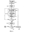
- FIG. 4 A simplified flow chart for programming the computing module 85 to store the table of values is shown in FIG. 4 .
- the values of ⁇ , a, b, ⁇ b , and ⁇ b to be used are input, as represented by block 100.
- Initial values of ⁇ ' and ⁇ are selected, as indicated by the block 101. These values could typically be the lowest possible expected values of E' and .
- Block 102 is then entered and represents the function of solving relationship (18), e.g. numerically, for h' and h".
- the current values of ⁇ ' and ⁇ are then stored in conjunction with the calculated values of h' and h", as represented by the block 103.
- the value of ⁇ ' is then incremented, as represented by the block 104.
- FIG. 5 is a simplified flow chart which illustrates how the look u p table can be used.
- the measured attenuation and phase are input (block 151), and relationships (10) and (14) are solved (block 152) to obtain values of h" and h', respectively.
- the previously stored look-up table can then be entered (block 153) to obtain the 6 and ⁇ which are stored in conjunction with the closest pair h', h".
- the values of E' and are then read out (block 154), such as for recording, display, and/or transmission.
- Sets of look-up tables (or graphs derived therefrom, which can be used in similar manner), can be generated for various types of common conditions, or can be generated after conditions are set or measured.
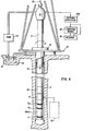
- FIG.6 there is illustrated an embodiment of the invention in the form of a logging-while-drilling apparatus and method.
- a platform and derrick 10 are positioned over a borehole 11 that is formed in the earth by rotary drilling.
- a drill string 12 is suspended within the borehole and includes a drill bit 15 at its lower end.
- the drill string 12, and the drill 15 attached thereto, is rotated by a rotating table 16 (energized by means not shown) which engages a kelly 17 at the upper end of the drill string.
- the drill string is suspended from a hook 18 attached to a travelling block (not shown).
- The-kelly is connected to the hook through a rotary swivel 19 which permits rotation of the drill string relative to the hook.
- Drilling fluid or mud 26 is contained in a pit 27 in the earth.
- a pump 29 pumps the drilling fluid into the drill string via a port in the swivel 19 to flow downward through the center of drill string 12.
- the drilling fluid exits the drill string via ports in the drill bit 15 and then circulates upward in the region between the outside of the drill string and the periphery of the borehole.
- the drilling fluid thereby carries formation cuttings to the surface of the earth, and the drilling fluid is returned to the pit 27 for recirculation.
- the small arrows in the FIGURE illustrate the typical direction of flow of the drilling fluid.
- Subsystem 250 mounted within the drill string 12, preferably near the drill bit 15, is a downhole sensing and transmitting subsystem 250.
- Subsystem 250 includes a measuring apparatus 200A which includes antennas T, R 1 , and R 2 , and operates in the manner described in conjunction with FIG. 1 or the other embodiments hereof.
- a transmitting portion of the downhole subsystem includes an acoustic transmitter 56 which generates an acoustic signal in the drilling fluid that is representaive of the measured downhole conditions
- acoustic transmitter which is known in the art, employs a device known as a "mud siren" which includes a slotted stator and a slotted rotor that rotates and repeatedly interrupts the flow of drilling fluid to establish a desired acoustic wave signal in the drilling fluid.
- Transmitter 56 is controlled by transmitter control and driving electronics 57 which includes analog-to-digital (A/D) circuitry that converts the signals representative of downhole conditions into digital form.
- A/D analog-to-digital
- the control and driving electronics 57 also includes a phase shift keying (PSK) modulator which conventionally produces driving signals for application to the transmitter 56.
- PSD phase shift keying
- the electronics 250 is representative of processing electronics, such as are used in FIG. 1 to produce the signals on conductors 60A and 70A. These signals are coupled to the transmitter control and driving electronics 57 which applies appropriate modulation to the mud siren of transmitter 56.
- the generated acoustic mud wave travels upward in the fluid through the center of the drill string at the speed of sound in the fluid.
- the acoustic wave is received at the surface of the earth, by transducers represented by reference numeral 31.
- the transducers which may for example be piezoelectric transducers, convert the received acoustic signals to electronic signals.
- the output of the transducers 31 is coupled to the uphole receiving subsystem 100 which is operative to demodulate the transmitted signals, which are then coupled to computing module 85 and recorder 95.
Abstract
Description
- This invention relates to borehole logging devices of the type wherein electromagnetic energy is used for measuring properties of formations surrounding a borehole and, more particularly, to a logging apparatus and method that can be used in either wireline logging applications or logging-while-drilling applications.
- In recent years, logging systems have been proposed for employing radio frequency electromagnetic energy in the range between about 10 MHz and 100 MHz to determine both the dielectric constant and the conductivity of formations surrounding a borehole. In this frequency range, dielectric constant and conductivity both have a substantial effect upon the propagation constant of electromagnetic energy propagating in the formations, so measurements of attenuation and phase can be used for solution of simultaneous equations to determine the dielectric constant and/or conductivity of formations through which the electromagnetic energy has passed. A device of this type is the deep propagation tool ("DPT"), an embodiment of which is described in U.S. Patent No. 4,209,747. This device includes a transmitting antenna, a "close" receiver antenna pair, and a "far" receiver antenna pair. Each of the transmitter and receiver antennas are coils wound in insulating media mounted on a metal cylindrical pipe which carries wiring to and/or from the coils. The coils are wound around the central axis of the pipe. Briefly, operation of the DPT logging device involves energizing the transmitter to emit electromagnetic energy at a frequency suitable for determination of both the electrical conductivity and the electrical permittivity of the surrounding formations. A portion of the electromagnetic energy which has traveled through the formations is received at the close and far differential receiver pairs. The signals detected at the far receiver pair are used to determine the phase shift of electromagnetic energy that has passed through the formations, and the signals detected at the close receiver pair are used to determine relative attenuation of the electromagnetic energy. The phase shift and attenuation are then employed to obtain electrical permittivity and electrical conductivity of the formations.
- Various techniques of logging have been proposed for use in logging-while-drilling systems. In the U.S. Patent Nos. 3,305,771 and 3,408,561 there is disclosed a well logging technique for determining formation conductivity (or resistivity} by employing toroidal solenoid antennas to launch a low frequency (e.g. 500 Hertz) current in a conductive sub on which the antennas are mounted. In one version of the technique, the logging device is urged against the borehole wall so that a current can flow in the device between the antennas and then through the formations and back into the device. In another version, contact electrodes extend outwardly from the device and contact the borehole wall in order to provide current paths to and from the formations. In a further form of that device wherein logging-while-drilling is effected, the described current loop passes through the metal sub which now forms part of the drill string, and then through the drill bit, the formations, and then back into the drill string. In each case, the receiving antenna or antennas measure the amount of current that flows in a loop that includes the conductive body or body portion of the logging device, and the formations. The referenced type of logging devices are advantageous in that they can be employed in logging-while-drilling applications as well as in conventional wireline logging. However, the need to establish a current loop that includes the formations, such as by making direct contact with the formations, can be problematic.. Also, the frequency of the electrical energy employed is necessarily limiting on the nature of the measurement and the type of information that can be obtained.
- It is among the objects of the present invention to provide a logging device which can be employed as a wireline tool or as a logging-while-drilling measurement tool. It is a further object of the invention to provide a device that is capable of electromagnetic logging at frequencies that are useful for measurement of conductivity and/or dielectric constant of subsurface formations. It is another object of the invention to provide a logging device that is capable of operating over a range of different frequencies so as to permit measurement of properties of formations at different depths of investigation.
- One aspect of the invention is directed to a method for investigating properties of earth formations surrounding a borehole, comprising the steps of: providing a generally tubular electrically conductive body in the borehole; generating, at a transmitter location on said body, electromagnetic energy having primarily transverse magnetic mode components which are guided by such body; and receiving the transverse magnetic mode components of the electromagnetic energy at a receiver location on the body.
- Another apsect of the invention is directed to apparatus for investigating properties of earth formations surrounding a borehole, comprising: a logging device moveable through the borehole, such device including a generally tubular electrically conductive body portion; energizing means; transmitting antenna means, mounted on said logging device and coupled to said energizing means, for generating electromagnetic energy having primarily transverse magnetic components; and receiving antenna means, mounted on said logging device in spaced relation to said transmitting antenna means, for receiving the transmitted electromagnetic energy, said receiving antenna means being adapted to be primarily sensitive to the transverse magnetic mode componets of electromagnetic energy.
- In contrast to the types of electromagnetic logging devices which utilize a wave that diverges in all directions from a transmitter, the present invention exploits electromagnetic energy that is guided along the borehole. The guiding of the energy is provided by the conductive body of the logging device. In some cases, the device body, mud-filled borehole, and external formation act as a generally cylindrical waveguide structure similar to a coaxial transmission line. The lowest order waveguide mode travels, in either the single conductor or coaxial model, with much less attenuation than any other mode. It is an axially symetric, transverse magnetic mode (TMoo), which has no low frequency cut-off. When formation conductivity σt is less than the mud conductivity σm, the velocity and attenuation of the TMoo mode is very close to the velocity and attenuation of a plane wave propagating in the formation. In this case, the attenuation of the mode is fairly insensitive to the diameter of the borehole and the conductivity and dielectric constant of the mud. accordingly, the present device is well suited for measurement of the formation conductivity and dielectric constant, especially in situations where water-based muds are employed.
- In a form of the present invention, means are provided for varying the frequency of operation of the logging apparatus by controlling the operating frequency of the energizing means. The frequency can be controlled while the device is downhole. An advantage of utilizing a logging device that employs the transverse magnetic mode component of the electromagnetic signal is that this mode does not readily cut off or greatly attenuate over the relatively wide range of operating frequencies. By varying the operating frequency, and therefore the skin depth of the generated electromagnetic energy, the effective depth of investigation of the device can be varied either during a given logging run or as between different logging runs. Also, variation of frequency can be used to change the relative degree to which the electromagnetic energy is sensitive to the conductivity and dielectric constant of the formations.
- Further features and advantages of the invention will become more readily apparent from the following detailed description when taken in conjunction with the accompanying drawings.
-
- FIG. 1 is a block diagram of an apparatus in accordance with an embodiment of the invention.
- FIG. 2 is a block diagram of an embodiment of the
amplitude comparator 60 of FIG. 1. - FIG. 3 is a block diagram of an embodiment of the
phase detector 70 of FIG. 1. - FIG. 4 is a flow diagram of the routine for generating a look-up table that can be used to obtain formation conductivity and/or dielectric constant.
- FIG. 5 is a flow diagram of the routine for using the look-up table.
- FIG. 6 illustrates a logging-while-drilling system that employs the invention.
- Referring to FIG. 1, there is shown an embodiment of an apparatus in accordance with the invention, and which can be used for practising the method of the invention, for investigating
subsurface formations 31 traversed by aborehole 32. Theborehole 32 is preferably filled with a water-based drilling mud. The borehole may be open or cased with a nonconductive material. The investigating apparatus.orlogging device 30 is suspended in theborehole 32 on an armored cable 33, the length of which substantially determines the relative depth of thedevice 30. The cable length is controlled by suitable means at the surface such as a drum and winch mechanism (not shown). The armored cable 33 is rewound on the drum to raise thedevice 30 toward the surface as formation characteristics are measured. Depth measurements are provided by ameasure wheel 96 which is rotated as a result of contact with cable 33. Pulses provided by rotation ofmeasure wheel 96 are applied to arecorder 95 to provide a record of the depths at which measurements are being taken. - The
logging device 30 includes a tubular electrically conductive support/guidingmember 200 which may be formed of a conductive metal. Mounted inmember 200 are a transmitter antenna T, a close receiver antenna R1, and a far receiver coil R2. In the present embodiment each of the antennas comprises a toroidal solenoid which is preferably recessed into an annular slot in themember 200. The antennas are electrically isolated and protected by encasing them in an insulating dielectric material, for example, that fills the slot. Thetubular member 200 carries wires to and/or from the antennas and may also contain electronic. components of the logging device. Alternatively, a separate cartridge may be provided for this purpose. Themember 200 helps prevent interference at the antennas from the wires or components therein, but its primary purpose herein is as a guiding vehicle for the transverse magnetic mode components of the electromagnetic wave energy. - A variable
frequency oscillator module 45 can operate in the present embodiment in the range between about 10 KHz and 100 Mhz. (and preferably in therange 10 MHz to 30 MHz). The output of the oscillator is coupled to the transmitter T through anamplifier 46 andtuning circuit 47. The toroidal solenoid transmitting antenna T, in conjunction with the guidingmember 200 produces electromagnetic energy having primarily transverse magnetic mode components. The toroidal solenoid receiving antennas R1 and R2 have primary sensitivity to the transverse magnetic mode components of the received signal. - The outputs of receivers R1 and R2 are applied, through tuning
circuits 21 and 22, respectively, andamplifiers amplitude comparator 60 and aphase detector circuit 70. The output ofphase detector 70 is a signal level which is proportional to the phase difference ϕ between the signals received at R1 and R2. The output ofamplitude comparator 60 is a signal level which is proportional to the amplitude ratio of the signals received at R2 and R1. - FIG. 2 discloses an embodiment of the
amplitude comparator circuit 60. To simplify the process of amplitude detection, the outputs ofamplifiers mixer circuits IF stage amplifiers detectors ratio circuit 620 which generates the signal online 60A (FIG. 1) that is representative of the amplitude ratio of the wave energy received at R2 and Rl. - FIG. 3 discloses an embodiment of the
phase comparator circuit 70 of FIG. 1. In a manner similar to FIG. 2, the outputs ofamplifiers mixers 703 and 713, respectively, whose outputs are, in turn, coupled to filter 704 andamplifier 705 andfilter 714 andamplifier 715, respectively. The outputs ofamplifiers crossing detector 706 is coupled to the set terminal of a flip-flop 720, and the output of the zerocrossing detector 716 is coupled to the reset terminal of the flip-flop 720. The zero crossing detectors are operative to generate an output only for excursions through zero in the positive-going direction. Accordingly, during each cycle the energy arriving first at receiver R1 will result in an output of zerocrossing detector 706 which, in turn, sets the flip-flop 720. When the signal subsequently arrives at receiver R2, the resultant output of zerocrossing detector 716 will reset the flip-flop 720. Accordingly, the output of flip-flop 720 is a pulse having a duration which represents the phase difference between the two signals. The output of flip-flop 720 is coupled to anintegrator 730 whose output is thesignal 70A; i.e,, an analog signal representative of the phase difference as between the signals received at receivers R2 and R1. It will be understood that the advantageous noise-eliminating technique described in the Calvert U.S. Patent No, 3,849,721, with or without borehole compensation techniques, can be employed, if desired. If borehole compensation is utilized, a second transmitter can be located on the opposite side of the receivers, and the receiver pairs can be adapted to alternately reverse roles as the transmitters are switched. Alternatively, one could, if desired, employ a time-processed borehole-compensation technique. - The outputs of the
phase detector circuit 70 and theamplitude comparison circuit 60 are transmitted to the surface over theconductors computing module 85 which computes values of conductivity and dielectric constant. These values are recorded byrecorder 95. - For initial understanding of the theory of operation, consider a simplified model of metal tube of radius a embedded in a homogeneous medium of conductivity σ, magnetic permeability µo (for non-magnetic media) and relative dielectric constant ε1. As is well known, the metal tube will allow a transverse magnetic field mode to propagate along the direction of the pipe (see e.g. Electromagnetic Theory, Stratton, McGraw Hill, 1941). As is shown in Stratton, if the metal tube has a much higher conductivity than the homogeneous medium, the principle TM mode propagates according to the characteristics of the external medium.
- Assume that the principle TM mode has been excited, for example, by a toroidal solenoid transmitter. The signal detected by a toroidal receiver placed at a location Z along the metal tube will be


- The propagation constant, h, has real and imaginary parts


- The amplitudes of the signals in the near and far receivers are


- The imaginary part of h (h'') is given by

- The phase at the near and far receivers is given by


- Thus, a measurement of the phase difference and a measurement of the amplitude ratio between the near and far receivers yields the real and imaginary parts of h.
- If the conductivity of the metal tube is much larger than the conductivity of the homogeneous medium, the propagation constant (see e.g. Stratton) of the principle TM mode is given by


- Accordingly, E' andδ could be determined, in this simplified model, from the near and far amplitudes and phases using relationships (10), (14), .(16) and (17).

- Consider next a model which includes a borehole. In this case, there will still be a principle Transverse Magnetic field mode, but its propagation constant will not be given exactly by relationship (15). The relationships used to determine the complex components of h would still be valid. However, the relationship (16) and (17) may involve some error in determining E' andfrom h. Accordingly, in the present model, let the borehole fluid'medium have a radius b, with relative dielectric constant

 b. The solution for the propagation constant h, given a, b,
 b, E', and
 , is known (see Wait and Fuller, "Transmission Live Theory for an Insulated Linear Antenna in a Fluid or Air-Filled Borehole", Applied Physics, Volume 1, 1973). In Wait et al, the problem of an insulated metal tube in a borehole in a formation is presented, and a method for obtaining h is set forth. For the purposes hereof, the metal tube is uninsulated. Therefore, the solution derived in the reference can be modified for our purposes if the insulating region is eliminated from the analysis.
- Adapting the analysis from this reference, a method for obtaining h (when a, b,
 b, E', and σ are known) is by solving


- Various techniques, well known in the art, could be employed to obtain and record ∈' and/or σ from the measured values and the relationships set forth, either at the well logging site or at a remote location. For example, a small general purpose digital computer can be used as
computing module 85 and a look-up table technique can be employed to obtain values of the conductivity and electric permit- ivity from the measured values of attenuation and phase. Briefly, the procedure is as follows: A look-up table is compiled for a particular set of given conditions of angular frequency ω, tool radius a, borehole-radius b, borehole mud conductivity and borehole mud dielectric constant ∈'b. Given these conditions, relationship (18) can be used to establish the look-up table by selecting pairs of values ofand E', and using relationships (16) and (17) to obtain a pair of values h' and h", that satisfy the relationship (18). The procedure is then repeated, at suitable increments, for all pairs of and E' within the ranges of interest, storing in the table each corresponding pair of values h', h". To use the look-up table, when values of attenuation and phase are measured, and relationships (10) and (14) are utilized to obtain values of h" and h', respectively. The look-up table can then be entered, the closest corresponding pair of values h', h" is located, and the corresponding pair of values for
 and E' are read out as the determined conductivity and dielectric constant of the investigated formations. These values can then be recorded on recorder 95 (FIG. 1).
- A simplified flow chart for programming the
computing module 85 to store the table of values is shown in FIG. 4. The values of ω, a, b, σb, and ∈b to be used are input, as represented byblock 100. Initial values of ∈' and σ are selected, as indicated by theblock 101. These values could typically be the lowest possible expected values of E' and.
Block 102 is then entered and represents the function of solving relationship (18), e.g. numerically, for h' and h". The current values of ∈' and σ are then stored in conjunction with the calculated values of h' and h", as represented by theblock 103. The value of ∈' is then incremented, as represented by the block 104. 6 is then tested (diamond 105) to determine if it has reached the maximum value of ∈' to be used. If not, block 102 is reentered, and new values are stored in the table. When ∈' has been incremented over its full range, the answer to the inquiry ofdiamond 105 will be "yes" and block 106 is entered, this block representing the incrementing of σ. σ is then tested (diamond 107) to determine if it has reached the maximum value of σ to be utilized. If not, ∈' is again initialized, block 102 is again entered and, as previously described, a new set of values will be determined as ∈' is iterated over its full range for this new value of. This procedure will continue until has reached its maximum value whereupon the routine is over and the full table of values has been stored.
- FIG. 5 is a simplified flow chart which illustrates how the look up table can be used. The measured attenuation and phase are input (block 151), and relationships (10) and (14) are solved (block 152) to obtain values of h" and h', respectively. The previously stored look-up table can then be entered (block 153) to obtain the 6 and σ which are stored in conjunction with the closest pair h', h". The values of E' andare then read out (block 154), such as for recording, display, and/or transmission. Sets of look-up tables (or graphs derived therefrom, which can be used in similar manner), can be generated for various types of common conditions, or can be generated after conditions are set or measured.

- Alternatives to the table look-up technique would be a curve matching technique or direct iterative numerical solution of the relationships set forth. A further possible approach is to provide a special purpose analog or digital computer which provides output functions that simulate families of curves which represent the relationships set forth. It will also be recognized that by using the described logging device in suitably large test pit borehole, stored values can be obtained empirically.
- Referring to FIG.6, there is illustrated an embodiment of the invention in the form of a logging-while-drilling apparatus and method. A platform and
derrick 10 are positioned over a borehole 11 that is formed in the earth by rotary drilling. Adrill string 12 is suspended within the borehole and includes adrill bit 15 at its lower end. Thedrill string 12, and thedrill 15 attached thereto, is rotated by a rotating table 16 (energized by means not shown) which engages akelly 17 at the upper end of the drill string. The drill string is suspended from ahook 18 attached to a travelling block (not shown). The-kelly is connected to the hook through arotary swivel 19 which permits rotation of the drill string relative to the hook. Drilling fluid ormud 26 is contained in apit 27 in the earth. Apump 29 pumps the drilling fluid into the drill string via a port in theswivel 19 to flow downward through the center ofdrill string 12. The drilling fluid exits the drill string via ports in thedrill bit 15 and then circulates upward in the region between the outside of the drill string and the periphery of the borehole. As is well known, the drilling fluid thereby carries formation cuttings to the surface of the earth, and the drilling fluid is returned to thepit 27 for recirculation. The small arrows in the FIGURE illustrate the typical direction of flow of the drilling fluid. - Mounted within the
drill string 12, preferably near thedrill bit 15, is a downhole sensing and transmitting subsystem 250. Subsystem 250 includes a measuringapparatus 200A which includes antennas T, R1, and R2, and operates in the manner described in conjunction with FIG. 1 or the other embodiments hereof. A transmitting portion of the downhole subsystem includes anacoustic transmitter 56 which generates an acoustic signal in the drilling fluid that is representaive of the measured downhole conditions, one suitable type or acoustic transmitter, which is known in the art, employs a device known as a "mud siren" which includes a slotted stator and a slotted rotor that rotates and repeatedly interrupts the flow of drilling fluid to establish a desired acoustic wave signal in the drilling fluid.Transmitter 56 is controlled by transmitter control and drivingelectronics 57 which includes analog-to-digital (A/D) circuitry that converts the signals representative of downhole conditions into digital form. The control and drivingelectronics 57 also includes a phase shift keying (PSK) modulator which conventionally produces driving signals for application to thetransmitter 56. The electronics 250 is representative of processing electronics, such as are used in FIG. 1 to produce the signals onconductors electronics 57 which applies appropriate modulation to the mud siren oftransmitter 56. - The generated acoustic mud wave travels upward in the fluid through the center of the drill string at the speed of sound in the fluid. The acoustic wave is received at the surface of the earth, by transducers represented by
reference numeral 31. The transducers, which may for example be piezoelectric transducers, convert the received acoustic signals to electronic signals. The output of thetransducers 31 is coupled to theuphole receiving subsystem 100 which is operative to demodulate the transmitted signals, which are then coupled tocomputing module 85 andrecorder 95. - It will be understood that alternative techniques can be employed for communicating logging information from
device 200A to the surface of the earth. - The invention has been described with reference to particular preferred embodiments, but variations within the spirit and scope of the invention will occur to those skilled in the art. For example, while two receivers and a single transmitter are shown in the illustrated embodiments, it will be understood that three or more receivers and/or two or more transmitters could be employed. Also, the operating frequency could be varied, uphole or downhole, and before or during a logging run. Finally, while toroidal solenoid antennas are presently preferred, electric dipole type antennas, designed to yield substantial TM mode, could alternatively be employed.
Claims (14)
Applications Claiming Priority (2)
| Application Number | Priority Date | Filing Date | Title |
|---|---|---|---|
| US430571 | 1982-09-30 | ||
| US06/430,571 US4553097A (en) | 1982-09-30 | 1982-09-30 | Well logging apparatus and method using transverse magnetic mode |
Publications (3)
| Publication Number | Publication Date |
|---|---|
| EP0105801A2 true EP0105801A2 (en) | 1984-04-18 |
| EP0105801A3 EP0105801A3 (en) | 1985-07-03 |
| EP0105801B1 EP0105801B1 (en) | 1991-05-08 |
Family
ID=23708119
Family Applications (1)
| Application Number | Title | Priority Date | Filing Date |
|---|---|---|---|
| EP83401907A Expired - Lifetime EP0105801B1 (en) | 1982-09-30 | 1983-09-29 | Well logging apparatus and method using transverse magnetic mode |
Country Status (12)
| Country | Link |
|---|---|
| US (1) | US4553097A (en) |
| EP (1) | EP0105801B1 (en) |
| AU (1) | AU1973083A (en) |
| BR (1) | BR8305335A (en) |
| DE (1) | DE3382273D1 (en) |
| DK (1) | DK453083A (en) |
| ES (1) | ES8502205A1 (en) |
| GR (1) | GR79422B (en) |
| MA (1) | MA19908A1 (en) |
| MX (1) | MX155292A (en) |
| NO (1) | NO157756C (en) |
| OA (1) | OA07552A (en) |
Cited By (9)
| Publication number | Priority date | Publication date | Assignee | Title |
|---|---|---|---|---|
| US4577153A (en) * | 1985-05-06 | 1986-03-18 | Stolar, Inc. | Continuous wave medium frequency signal transmission survey procedure for imaging structure in coal seams |
| GB2164744A (en) * | 1984-09-24 | 1986-03-26 | Nl Industries Inc | Apparatus and method for estimating formation characteristics of exposed bottomhole formation |
| USRE32563E (en) * | 1985-05-06 | 1987-12-15 | Stolar, Inc. | Continuous wave medium frequency signal transmission survey procedure for imaging structure in coal seams |
| EP0601664A1 (en) * | 1992-12-07 | 1994-06-15 | Grondmechanica Delft | Measuring device for underground probing, and method for the application thereof |
| EP0840142A2 (en) * | 1996-10-30 | 1998-05-06 | Baker Hughes Incorporated | Improved method and apparatus for determining dip angle, and horizontal and vertical conductivities |
| GB2412744A (en) * | 2004-04-01 | 2005-10-05 | Schlumberger Holdings | Lateral resistivity antenna combined with induction/propagation antennas |
| WO2007056320A2 (en) * | 2005-11-04 | 2007-05-18 | Halliburton Energy Services, Inc. | Permittivity measurements with oil-based mud imaging tool |
| US8030937B2 (en) | 2005-12-13 | 2011-10-04 | Halliburton Energy Services, Inc. | Multiple frequency based leakage correction for imaging in oil based muds |
| US8183863B2 (en) | 2005-11-10 | 2012-05-22 | Halliburton Energy Services, Inc. | Displaced electrode amplifier |
Families Citing this family (47)
| Publication number | Priority date | Publication date | Assignee | Title |
|---|---|---|---|---|
| US4785247A (en) * | 1983-06-27 | 1988-11-15 | Nl Industries, Inc. | Drill stem logging with electromagnetic waves and electrostatically-shielded and inductively-coupled transmitter and receiver elements |
| US4651101A (en) * | 1984-02-27 | 1987-03-17 | Schlumberger Technology Corporation | Induction logging sonde with metallic support |
| US4949045A (en) * | 1987-10-30 | 1990-08-14 | Schlumberger Technology Corporation | Well logging apparatus having a cylindrical housing with antennas formed in recesses and covered with a waterproof rubber layer |
| US4968940A (en) * | 1987-10-30 | 1990-11-06 | Schlumberger Technology Corporation | Well logging apparatus and method using two spaced apart transmitters with two receivers located between the transmitters |
| US4899112A (en) * | 1987-10-30 | 1990-02-06 | Schlumberger Technology Corporation | Well logging apparatus and method for determining formation resistivity at a shallow and a deep depth |
| US5081419A (en) * | 1990-10-09 | 1992-01-14 | Baker Hughes Incorporated | High sensitivity well logging system having dual transmitter antennas and intermediate series resonant |
| US4940943A (en) * | 1988-04-19 | 1990-07-10 | Baroid Technology, Inc. | Method and apparatus for optimizing the reception pattern of the antenna of a propagating electromagnetic wave logging tool |
| US5041975A (en) * | 1988-09-06 | 1991-08-20 | Schlumberger Technology Corporation | Borehole correction system for an array induction well-logging apparatus |
| US4933640A (en) * | 1988-12-30 | 1990-06-12 | Vector Magnetics | Apparatus for locating an elongated conductive body by electromagnetic measurement while drilling |
| US5160925C1 (en) * | 1991-04-17 | 2001-03-06 | Halliburton Co | Short hop communication link for downhole mwd system |
| DE69223589T2 (en) * | 1991-10-22 | 1998-12-10 | Halliburton Energy Serv Inc | Procedure for measuring boreholes during drilling |
| US5200705A (en) * | 1991-10-31 | 1993-04-06 | Schlumberger Technology Corporation | Dipmeter apparatus and method using transducer array having longitudinally spaced transducers |
| US5235285A (en) * | 1991-10-31 | 1993-08-10 | Schlumberger Technology Corporation | Well logging apparatus having toroidal induction antenna for measuring, while drilling, resistivity of earth formations |
| US5339037A (en) * | 1992-10-09 | 1994-08-16 | Schlumberger Technology Corporation | Apparatus and method for determining the resistivity of earth formations |
| NO306522B1 (en) * | 1992-01-21 | 1999-11-15 | Anadrill Int Sa | Procedure for acoustic transmission of measurement signals when measuring during drilling |
| US5389881A (en) * | 1992-07-22 | 1995-02-14 | Baroid Technology, Inc. | Well logging method and apparatus involving electromagnetic wave propagation providing variable depth of investigation by combining phase angle and amplitude attenuation |
| US5463320A (en) * | 1992-10-09 | 1995-10-31 | Schlumberger Technology Corporation | Apparatus and method for determining the resitivity of underground formations surrounding a borehole |
| US5563512A (en) * | 1994-06-14 | 1996-10-08 | Halliburton Company | Well logging apparatus having a removable sleeve for sealing and protecting multiple antenna arrays |
| US5594343A (en) * | 1994-12-02 | 1997-01-14 | Schlumberger Technology Corporation | Well logging apparatus and method with borehole compensation including multiple transmitting antennas asymmetrically disposed about a pair of receiving antennas |
| US5900733A (en) * | 1996-02-07 | 1999-05-04 | Schlumberger Technology Corporation | Well logging method and apparatus for determining downhole Borehole fluid resistivity, borehole diameter, and borehole corrected formation resistivity |
| US5963036A (en) * | 1996-02-07 | 1999-10-05 | Schlumberger Technology Corporation | Well logging apparatus and method for determining properties of earth formations that have been invaded by borehole fluid |
| US5886526A (en) * | 1996-06-19 | 1999-03-23 | Schlumberger Technology Corporation | Apparatus and method for determining properties of anisotropic earth formations |
| US6084403A (en) * | 1997-03-31 | 2000-07-04 | Cedar Bluff Group Corporation | Slim-hole collar locator and casing inspection tool with high-strength pressure housing |
| US6064210A (en) * | 1997-11-14 | 2000-05-16 | Cedar Bluff Group Corporation | Retrievable resistivity logging system for use in measurement while drilling |
| US7659722B2 (en) | 1999-01-28 | 2010-02-09 | Halliburton Energy Services, Inc. | Method for azimuthal resistivity measurement and bed boundary detection |
| US6163155A (en) | 1999-01-28 | 2000-12-19 | Dresser Industries, Inc. | Electromagnetic wave resistivity tool having a tilted antenna for determining the horizontal and vertical resistivities and relative dip angle in anisotropic earth formations |
| US6445187B1 (en) | 2000-04-10 | 2002-09-03 | Jerry R. Montgomery | System for the measurement of electrical characteristics of geological formations from within steel cased wells using magnetic circuits |
| US6958610B2 (en) * | 2001-06-03 | 2005-10-25 | Halliburton Energy Services, Inc. | Method and apparatus measuring electrical anisotropy in formations surrounding a wellbore |
| US7227363B2 (en) * | 2001-06-03 | 2007-06-05 | Gianzero Stanley C | Determining formation anisotropy based in part on lateral current flow measurements |
| US6791330B2 (en) | 2002-07-16 | 2004-09-14 | General Electric Company | Well logging tool and method for determining resistivity by using phase difference and/or attenuation measurements |
| US7388379B2 (en) * | 2003-05-01 | 2008-06-17 | Pathfinder Energy Services, Inc. | Series-resonant tuning of a downhole loop antenna |
| US20070057738A1 (en) * | 2003-07-02 | 2007-03-15 | Takahiro Baba | Oscillator device and transmission and reception device |
| US7080699B2 (en) * | 2004-01-29 | 2006-07-25 | Schlumberger Technology Corporation | Wellbore communication system |
| US7350568B2 (en) * | 2005-02-09 | 2008-04-01 | Halliburton Energy Services, Inc. | Logging a well |
| US20070024286A1 (en) * | 2005-07-27 | 2007-02-01 | Baker Hughes Incorporated | Compensation for tool disposition in LWD resistivity measurements |
| WO2007149106A1 (en) * | 2006-06-19 | 2007-12-27 | Halliburton Energy Services, Inc. | Antenna cutout in a downhole tubular |
| RU2394270C1 (en) | 2006-07-11 | 2010-07-10 | Хэллибертон Энерджи Сервисиз, Инк. | Modular instrument unit for geo-control |
| CA2650481C (en) | 2006-07-12 | 2013-09-03 | Halliburton Energy Services, Inc. | Method and apparatus for building a tilted antenna |
| WO2008021868A2 (en) | 2006-08-08 | 2008-02-21 | Halliburton Energy Services, Inc. | Resistivty logging with reduced dip artifacts |
| US8274289B2 (en) * | 2006-12-15 | 2012-09-25 | Halliburton Energy Services, Inc. | Antenna coupling component measurement tool having rotating antenna configuration |
| AU2007349251B2 (en) | 2007-03-16 | 2011-02-24 | Halliburton Energy Services, Inc. | Robust inversion systems and methods for azimuthally sensitive resistivity logging tools |
| AU2008348131B2 (en) | 2008-01-18 | 2011-08-04 | Halliburton Energy Services, Inc. | EM-guided drilling relative to an existing borehole |
| US8581592B2 (en) | 2008-12-16 | 2013-11-12 | Halliburton Energy Services, Inc. | Downhole methods and assemblies employing an at-bit antenna |
| GB2486759B (en) | 2010-01-22 | 2014-09-03 | Halliburton Energy Serv Inc | Method and apparatus for resistivity measurements |
| MX342269B (en) | 2012-06-25 | 2016-09-22 | Halliburton Energy Services Inc | Tilted antenna logging systems and methods yielding robust measurement signals. |
| CN103643946A (en) * | 2013-12-16 | 2014-03-19 | 西南石油大学 | Dual-electrical-parameter logging instrument while drilling |
| US10309214B2 (en) | 2015-10-06 | 2019-06-04 | Groundmetrics, Inc. | System and method for performing distant geophysical survey |
Citations (4)
| Publication number | Priority date | Publication date | Assignee | Title |
|---|---|---|---|---|
| US2220070A (en) * | 1936-03-24 | 1940-11-05 | Schlumberger Well Surv Corp | Method of and apparatus for magnetically exploring earth strata |
| US2455940A (en) * | 1944-11-28 | 1948-12-14 | Gulf Research Development Co | Method of geophysical exploration by microwaves |
| US3305771A (en) * | 1963-08-30 | 1967-02-21 | Arps Corp | Inductive resistivity guard logging apparatus including toroidal coils mounted on a conductive stem |
| US4209747A (en) * | 1977-09-21 | 1980-06-24 | Schlumberger Technology Corporation | Apparatus and method for determination of subsurface permittivity and conductivity |
Family Cites Families (14)
| Publication number | Priority date | Publication date | Assignee | Title |
|---|---|---|---|---|
| US2333883A (en) * | 1939-05-31 | 1943-11-09 | Phillips Petroleum Co | Well surveying device |
| US3408561A (en) * | 1963-07-29 | 1968-10-29 | Arps Corp | Formation resistivity measurement while drilling, utilizing physical conditions representative of the signals from a toroidal coil located adjacent the drilling bit |
| FR1527757A (en) * | 1966-09-29 | 1968-06-07 | Schlumberger Prospection | Electromagnetic device for measuring the resistivity of formations crossed by a sounding |
| US3449657A (en) * | 1966-11-14 | 1969-06-10 | Chevron Res | Helical antenna for irradiating an earth formation penetrated by a borehole and method of using same |
| US3629937A (en) * | 1966-11-14 | 1971-12-28 | Chevron Res | Method of forming a helical antenna |
| US3582766A (en) * | 1969-11-13 | 1971-06-01 | Keigo Iizuka | Passively controlled duplexer-coupler applied to a helical antenna for use in a borehole penetrating an earth formation |
| US3646562A (en) * | 1970-06-03 | 1972-02-29 | Us Navy | Helical coil coupled to a live tree to provide a radiating antenna |
| US3849721A (en) * | 1973-08-23 | 1974-11-19 | Schlumberger Technology Corp | Microwave logging apparatus having dual processing channels |
| CA1040261A (en) * | 1973-08-23 | 1978-10-10 | Schlumberger Canada Limited | Method and apparatus for investigating earth formations |
| US4312003A (en) * | 1980-09-15 | 1982-01-19 | Mine Safety Appliances Company | Ferrite antenna |
| US4334227A (en) * | 1980-09-26 | 1982-06-08 | A.P.C. Industries, Inc. | Electronic marker device and method of making same |
| US4348672A (en) * | 1981-03-04 | 1982-09-07 | Tele-Drill, Inc. | Insulated drill collar gap sub assembly for a toroidal coupled telemetry system |
| US4458248A (en) * | 1982-04-26 | 1984-07-03 | Haramco Research, Inc. | Parametric antenna |
| AU2907484A (en) * | 1983-06-27 | 1985-01-03 | N L Industries Inc. | Drill stem logging system |
-
1982
- 1982-09-30 US US06/430,571 patent/US4553097A/en not_active Expired - Lifetime
-
1983
- 1983-09-01 NO NO833131A patent/NO157756C/en unknown
- 1983-09-21 MX MX198779A patent/MX155292A/en unknown
- 1983-09-27 MA MA20131A patent/MA19908A1/en unknown
- 1983-09-28 BR BR8305335A patent/BR8305335A/en unknown
- 1983-09-29 EP EP83401907A patent/EP0105801B1/en not_active Expired - Lifetime
- 1983-09-29 AU AU19730/83A patent/AU1973083A/en not_active Abandoned
- 1983-09-29 DE DE8383401907T patent/DE3382273D1/en not_active Expired - Lifetime
- 1983-09-29 ES ES526073A patent/ES8502205A1/en not_active Expired
- 1983-09-29 GR GR72576A patent/GR79422B/el unknown
- 1983-09-29 OA OA58122A patent/OA07552A/en unknown
- 1983-09-30 DK DK453083A patent/DK453083A/en not_active Application Discontinuation
Patent Citations (4)
| Publication number | Priority date | Publication date | Assignee | Title |
|---|---|---|---|---|
| US2220070A (en) * | 1936-03-24 | 1940-11-05 | Schlumberger Well Surv Corp | Method of and apparatus for magnetically exploring earth strata |
| US2455940A (en) * | 1944-11-28 | 1948-12-14 | Gulf Research Development Co | Method of geophysical exploration by microwaves |
| US3305771A (en) * | 1963-08-30 | 1967-02-21 | Arps Corp | Inductive resistivity guard logging apparatus including toroidal coils mounted on a conductive stem |
| US4209747A (en) * | 1977-09-21 | 1980-06-24 | Schlumberger Technology Corporation | Apparatus and method for determination of subsurface permittivity and conductivity |
Non-Patent Citations (1)
| Title |
|---|
| APPLIED PHYSICS, Vol. 1, 311-316, 1973 * |
Cited By (14)
| Publication number | Priority date | Publication date | Assignee | Title |
|---|---|---|---|---|
| GB2164744A (en) * | 1984-09-24 | 1986-03-26 | Nl Industries Inc | Apparatus and method for estimating formation characteristics of exposed bottomhole formation |
| US4577153A (en) * | 1985-05-06 | 1986-03-18 | Stolar, Inc. | Continuous wave medium frequency signal transmission survey procedure for imaging structure in coal seams |
| USRE32563E (en) * | 1985-05-06 | 1987-12-15 | Stolar, Inc. | Continuous wave medium frequency signal transmission survey procedure for imaging structure in coal seams |
| EP0601664A1 (en) * | 1992-12-07 | 1994-06-15 | Grondmechanica Delft | Measuring device for underground probing, and method for the application thereof |
| EP0840142A2 (en) * | 1996-10-30 | 1998-05-06 | Baker Hughes Incorporated | Improved method and apparatus for determining dip angle, and horizontal and vertical conductivities |
| EP0840142A3 (en) * | 1996-10-30 | 2001-01-31 | Baker Hughes Incorporated | Improved method and apparatus for determining dip angle, and horizontal and vertical conductivities |
| GB2412744A (en) * | 2004-04-01 | 2005-10-05 | Schlumberger Holdings | Lateral resistivity antenna combined with induction/propagation antennas |
| GB2412744B (en) * | 2004-04-01 | 2006-07-05 | Schlumberger Holdings | A combined propagation and lateral resistivity downhole tool |
| WO2007056320A2 (en) * | 2005-11-04 | 2007-05-18 | Halliburton Energy Services, Inc. | Permittivity measurements with oil-based mud imaging tool |
| WO2007056320A3 (en) * | 2005-11-04 | 2009-05-07 | Halliburton Energy Serv Inc | Permittivity measurements with oil-based mud imaging tool |
| GB2441260B (en) * | 2005-11-04 | 2010-12-01 | Halliburton Energy Serv Inc | Permittivity measurements with oil-based mud imaging tool |
| US7888941B2 (en) | 2005-11-04 | 2011-02-15 | Halliburton Energy Services, Inc. | Permittivity measurements with oil-based mud imaging tool |
| US8183863B2 (en) | 2005-11-10 | 2012-05-22 | Halliburton Energy Services, Inc. | Displaced electrode amplifier |
| US8030937B2 (en) | 2005-12-13 | 2011-10-04 | Halliburton Energy Services, Inc. | Multiple frequency based leakage correction for imaging in oil based muds |
Also Published As
| Publication number | Publication date |
|---|---|
| GR79422B (en) | 1984-10-22 |
| MA19908A1 (en) | 1984-04-01 |
| NO833131L (en) | 1984-04-02 |
| AU1973083A (en) | 1984-04-05 |
| NO157756B (en) | 1988-02-01 |
| US4553097A (en) | 1985-11-12 |
| ES526073A0 (en) | 1984-12-16 |
| EP0105801B1 (en) | 1991-05-08 |
| ES8502205A1 (en) | 1984-12-16 |
| DK453083A (en) | 1984-03-31 |
| OA07552A (en) | 1985-03-31 |
| MX155292A (en) | 1988-02-12 |
| EP0105801A3 (en) | 1985-07-03 |
| NO157756C (en) | 1988-05-11 |
| BR8305335A (en) | 1984-05-08 |
| DE3382273D1 (en) | 1991-06-13 |
| DK453083D0 (en) | 1983-09-30 |
Similar Documents
| Publication | Publication Date | Title |
|---|---|---|
| EP0105801B1 (en) | Well logging apparatus and method using transverse magnetic mode | |
| US4107598A (en) | Electromagnetic wave logging system for determining resistivity and dielectric constant of earth formations | |
| US5672971A (en) | Well logging system arranged for stable, high-sensitivity reception of propagating electromagnetic waves | |
| EP0314573B1 (en) | Well logging apparatus and method | |
| EP0527089B1 (en) | Method and apparatus for determining horizontal conductivity and vertical conductivity of earth formations | |
| US4968940A (en) | Well logging apparatus and method using two spaced apart transmitters with two receivers located between the transmitters | |
| US5656930A (en) | Method for determining the anisotropic properties of a subterranean formation consisting of a thinly laminated sand/shale sequence using an induction type logging tool | |
| US4949045A (en) | Well logging apparatus having a cylindrical housing with antennas formed in recesses and covered with a waterproof rubber layer | |
| CA2245720C (en) | Well logging method and apparatus for nmr and resistivity measurements | |
| US4107597A (en) | Electromagnetic wave propagation well logging utilizing multiple phase shift measurement | |
| US4209747A (en) | Apparatus and method for determination of subsurface permittivity and conductivity | |
| US4185238A (en) | Apparatus and method for determination of subsurface permittivity and conductivity | |
| CA1062333A (en) | Movable oil measurement combining dual radio frequency induction and dual induction laterolog measurements | |
| EP0814349A2 (en) | Apparatus and method for determining properties of anisotropic earth formations | |
| US4845433A (en) | Apparatus for microinductive investigation of earth formations | |
| CA1040708A (en) | Combination radio frequency dielectric and conventional induction logging system | |
| US5241273A (en) | Method for controlling directional drilling in response to horns detected by electromagnetic energy propagation resistivity measurements | |
| CA1053755A (en) | Dielectric induction logging system for obtaining water and residual oil saturation of earth formations | |
| EP0793119A2 (en) | Well logging method and apparatus | |
| US4780678A (en) | Apparatus for microinductive investigation of earth formations | |
| US4594551A (en) | Method of deep penetration well logging using three receivers | |
| US5495174A (en) | Method and apparatus for detecting boundary stratum and adjusting the direction of drilling to maintain the drill string within a bed of interest | |
| US4712070A (en) | Apparatus for microinductive investigation of earth formations | |
| US20050122116A1 (en) | Method and apparatus for use of the real component of a magnetic field of multicomponent resistivity measurements | |
| EP0163574B1 (en) | Apparatus for microinductive investigation of earth formations |
Legal Events
| Date | Code | Title | Description |
|---|---|---|---|
| PUAI | Public reference made under article 153(3) epc to a published international application that has entered the european phase |
Free format text: ORIGINAL CODE: 0009012 |
|
| AK | Designated contracting states |
Designated state(s): DE FR GB IT NL |
|
| PUAL | Search report despatched |
Free format text: ORIGINAL CODE: 0009013 |
|
| AK | Designated contracting states |
Designated state(s): DE FR GB IT NL |
|
| 17P | Request for examination filed |
Effective date: 19860102 |
|
| 17Q | First examination report despatched |
Effective date: 19870811 |
|
| GRAA | (expected) grant |
Free format text: ORIGINAL CODE: 0009210 |
|
| AK | Designated contracting states |
Kind code of ref document: B1 Designated state(s): DE FR GB IT NL |
|
| PG25 | Lapsed in a contracting state [announced via postgrant information from national office to epo] |
Ref country code: IT Free format text: LAPSE BECAUSE OF FAILURE TO SUBMIT A TRANSLATION OF THE DESCRIPTION OR TO PAY THE FEE WITHIN THE PRESCRIBED TIME-LIMIT;WARNING: LAPSES OF ITALIAN PATENTS WITH EFFECTIVE DATE BEFORE 2007 MAY HAVE OCCURRED AT ANY TIME BEFORE 2007. THE CORRECT EFFECTIVE DATE MAY BE DIFFERENT FROM THE ONE RECORDED. Effective date: 19910508 |
|
| REF | Corresponds to: |
Ref document number: 3382273 Country of ref document: DE Date of ref document: 19910613 |
|
| ET | Fr: translation filed | ||
| PLBE | No opposition filed within time limit |
Free format text: ORIGINAL CODE: 0009261 |
|
| STAA | Information on the status of an ep patent application or granted ep patent |
Free format text: STATUS: NO OPPOSITION FILED WITHIN TIME LIMIT |
|
| 26N | No opposition filed | ||
| PG25 | Lapsed in a contracting state [announced via postgrant information from national office to epo] |
Ref country code: DE Effective date: 19920602 |
|
| PGFP | Annual fee paid to national office [announced via postgrant information from national office to epo] |
Ref country code: NL Payment date: 19920930 Year of fee payment: 10 |
|
| PG25 | Lapsed in a contracting state [announced via postgrant information from national office to epo] |
Ref country code: NL Effective date: 19940401 |
|
| NLV4 | Nl: lapsed or anulled due to non-payment of the annual fee | ||
| REG | Reference to a national code |
Ref country code: GB Ref legal event code: IF02 |
|
| PGFP | Annual fee paid to national office [announced via postgrant information from national office to epo] |
Ref country code: FR Payment date: 20020910 Year of fee payment: 20 |
|
| PGFP | Annual fee paid to national office [announced via postgrant information from national office to epo] |
Ref country code: GB Payment date: 20020925 Year of fee payment: 20 |
|
| PG25 | Lapsed in a contracting state [announced via postgrant information from national office to epo] |
Ref country code: GB Free format text: LAPSE BECAUSE OF EXPIRATION OF PROTECTION Effective date: 20030928 |
|
| REG | Reference to a national code |
Ref country code: GB Ref legal event code: PE20 |