EP0105718B1 - Carton blank transfer mechanism - Google Patents
Carton blank transfer mechanism Download PDFInfo
- Publication number
- EP0105718B1 EP0105718B1 EP83305849A EP83305849A EP0105718B1 EP 0105718 B1 EP0105718 B1 EP 0105718B1 EP 83305849 A EP83305849 A EP 83305849A EP 83305849 A EP83305849 A EP 83305849A EP 0105718 B1 EP0105718 B1 EP 0105718B1
- Authority
- EP
- European Patent Office
- Prior art keywords
- arm
- shaft
- drive
- transfer mechanism
- suction head
- Prior art date
- Legal status (The legal status is an assumption and is not a legal conclusion. Google has not performed a legal analysis and makes no representation as to the accuracy of the status listed.)
- Expired
Links
- 230000007246 mechanism Effects 0.000 title claims description 24
- 230000010355 oscillation Effects 0.000 claims description 6
- 230000005484 gravity Effects 0.000 description 1
Images


Classifications
-
- B—PERFORMING OPERATIONS; TRANSPORTING
- B31—MAKING ARTICLES OF PAPER, CARDBOARD OR MATERIAL WORKED IN A MANNER ANALOGOUS TO PAPER; WORKING PAPER, CARDBOARD OR MATERIAL WORKED IN A MANNER ANALOGOUS TO PAPER
- B31B—MAKING CONTAINERS OF PAPER, CARDBOARD OR MATERIAL WORKED IN A MANNER ANALOGOUS TO PAPER
- B31B50/00—Making rigid or semi-rigid containers, e.g. boxes or cartons
-
- B—PERFORMING OPERATIONS; TRANSPORTING
- B31—MAKING ARTICLES OF PAPER, CARDBOARD OR MATERIAL WORKED IN A MANNER ANALOGOUS TO PAPER; WORKING PAPER, CARDBOARD OR MATERIAL WORKED IN A MANNER ANALOGOUS TO PAPER
- B31B—MAKING CONTAINERS OF PAPER, CARDBOARD OR MATERIAL WORKED IN A MANNER ANALOGOUS TO PAPER
- B31B50/00—Making rigid or semi-rigid containers, e.g. boxes or cartons
- B31B50/02—Feeding or positioning sheets, blanks or webs
- B31B50/04—Feeding sheets or blanks
- B31B50/07—Feeding sheets or blanks by air pressure or suction
-
- B—PERFORMING OPERATIONS; TRANSPORTING
- B31—MAKING ARTICLES OF PAPER, CARDBOARD OR MATERIAL WORKED IN A MANNER ANALOGOUS TO PAPER; WORKING PAPER, CARDBOARD OR MATERIAL WORKED IN A MANNER ANALOGOUS TO PAPER
- B31B—MAKING CONTAINERS OF PAPER, CARDBOARD OR MATERIAL WORKED IN A MANNER ANALOGOUS TO PAPER
- B31B50/00—Making rigid or semi-rigid containers, e.g. boxes or cartons
- B31B50/02—Feeding or positioning sheets, blanks or webs
- B31B50/04—Feeding sheets or blanks
- B31B50/06—Feeding sheets or blanks from stacks
- B31B50/062—Feeding sheets or blanks from stacks from the underside of a magazine
Definitions
- This invention relates to new and useful improvements in transfer mechanisms for blanks. More particularly, it relates to a carton blanktrans- fer mechanism for transferring a carton blank from a hopper to a carton forming and applying apparatus which mechanism comprises an arm pivotally mounted on a shaft, a suction head mounted on the arm and first drive means for oscillating the arm.
- U.S. Patent specification No. 4034658 refers to a tray feeder for corrugated sheets stored in a gravity hopper.
- the sheets are fed in a continuous flow by a feed mechanism which includesvacuum (suction) means and asplitwheel roller system for withdrawing overhung upper portions of the foremost sheetfrom the hopper in a timed sequence.
- the present invention provides a carton blank transfer mechanism as described in the first paragraph above in which the suction head is pivotally mounted on the arms and in which the shaft on which said arm is pivotally mounted is rotatable and is driven by a second drive means for oscillating the suction head relative to the arm in timed relationship to the oscillation of the arm.
- the second drive means is operable to oscillate the suction head in the same direction of movement as that of the arm, whereby a relatively large degree of rotation of the blank being transferred may be effected.
- a drive shaft which carries an eccentric drive for pivoting the arm and a cam actuated drive for oscillating the suction head.
- the arm may be pivotally mounted on a rotating shaft which carries a drive wheel which, in turn, drives a driven wheel and the driven wheel, in turn, actuates a gear set so as to effect the pivoting of the suction head relative to the arm.
- FIG. 2 wherein there is illustrated two spaced apart vertical mounting plates 10 and 12.
- the mounting plates 10 and 12 carry horizontally aligned transverse bearings 14 and 16 in which there is rotatably journalled a transversely extending rotating shaft 18.
- the shaft 18 has rotatably journalled thereon bearings 20, 22 which, in turn, carry arms 24 and 26.
- each arm 24 or 26, is carried by a mounting block 28 which is fixedly secured to a respective one of the bearings 20, 22, and the block 28 has the arm 24 slidably passing therethrough with the arm being locked in an adjusted position by means of a locking screw 30 (Fig. 2).
- the mounting blocks 28 are joined together by a transverse shaft 32 to which the mounting blocks 28 are suitably fixed and so as to space apart the mounting blocks 28 and thus the arms 24, 26.
- Each arm 24, 26 has an offset end portion 34 (Fig. 1) which carries a pivot shaft 36 which is rotatably journalled relative thereto.
- Each pivot shaft 36 carries a mounting block 38 of a suction head 40 with the mounting block being offsetto one side of the respective arm, as shown in Figure 2.
- the mounting block38 issecuredto its respective pivot shaft 36 for pivoting therewith and carries a plurality of suction cups 42.
- Each arm 24, 26 also carries a driven shaft 44 adjacent its offset end.
- Each driven shaft 44 carries for oscillation therewith a drive sprocket 46 which is meshed with a driven sprocket 48 secured to the pivot shaft 36.
- the driven shaft 44 aiso carries a driven wheel 50 in the form of a sprocket which is coupled to a drive wheel 52, also in the form of a sprocket, by a drive element in the form of a chain 54.
- Each drive wheel 52 is fixedly secured to the rotatable shaft 18 for oscillation therewith.
- the mounting plate 10 carries a bearing unit 56 in which there is rotatably journalled a drive shaft 58.
- the drive shaft 58 extends through the mounting plate 10 and carries on the end thereof adjacent the arm 24 an eccentric drive unit 60 including an eccentric pin 62.
- An adjustable link 64 extends between through the eccentric pin 62 and one end of the shaft32.
- the drive shaft 58 also carries a cam 66.
- the cam 66 has associated therewith a follower mechanism which includes a lever 68 which is pivotally mounted on a pivot shaft 70 and carries at the center thereof a cam follower 72 which engages the cam 66.
- a crank arm 74 is adjustably clamped on one end of the rotatable shaft 18 and is connected to a free end of the lever 68 by means of a pivotal link 76.
- a tension spring 78 may be engaged with the lever 68 to retain the cam follower 72 in engagement with the surface of the cam 66.
- the rotating shaft 58 when it rotates, serves not only to oscillate the arms 24, 26, but also to oscillate the suction head 40 relative to the arms.
- the mechanism will include a suitable hopper 80 in which blanks B to be transferred are stored.
- the bottom blank faces downwardly generally at a 45° angle.
- the bottom blank when transferred, will be transferred to a generally horizontal position.
- the arms 24, 26 pivot through an angle on the order of 45° while the suction heads 40 pivot relative to the arms 24, 26 through an angle of 90° in the same direction of pivoting of the arms 24, 26. It is to be understood that in the return movement of the arms 24, 26, the suction heads 40 will pivot or rotate in the opposite direction.
- the carton applying machine will include a suitable drive from which a chain 82 is driven in the direction of the arrows in Figure 1.
- the chain 82 first passes over an idler sprocket 84 and then over a sprocket 86 which is carried by a shaft 88 (Fig. 2).
- the chain next passes over a sprocket 90 fixed to the shaft 58 and finally over an idler sprocket 92 carried by an idler shaft 94.
- the shaft 88 which is rotatably journalled in a bearing 96 carried by the mounting plate 10 is provided with a rotary valve 98 which has a fixed housing 100 which is connected to a vacuum source 102 by a vacuum line 104 and to the suction head 40 by vacuum lines 106.
- the suction heads 40 are energized in time relation to the rotation of the shaft 58 and thus in timed relation to the pivoting of the arms 24, 26.
Landscapes
- Supplying Of Containers To The Packaging Station (AREA)
- Sheets, Magazines, And Separation Thereof (AREA)
Description
- This invention relates to new and useful improvements in transfer mechanisms for blanks. More particularly, it relates to a carton blanktrans- fer mechanism for transferring a carton blank from a hopper to a carton forming and applying apparatus which mechanism comprises an arm pivotally mounted on a shaft, a suction head mounted on the arm and first drive means for oscillating the arm.
- A mechanism of the type thus described is illustrated in U.S. Patent specification No. 4034658 which refers to a tray feeder for corrugated sheets stored in a gravity hopper. The sheets are fed in a continuous flow by a feed mechanism which includesvacuum (suction) means and asplitwheel roller system for withdrawing overhung upper portions of the foremost sheetfrom the hopper in a timed sequence.
- The present invention provides a carton blank transfer mechanism as described in the first paragraph above in which the suction head is pivotally mounted on the arms and in which the shaft on which said arm is pivotally mounted is rotatable and is driven by a second drive means for oscillating the suction head relative to the arm in timed relationship to the oscillation of the arm.
- Advantageously, the second drive means is operable to oscillate the suction head in the same direction of movement as that of the arm, whereby a relatively large degree of rotation of the blank being transferred may be effected.
- Moreover, there may be provided a drive shaft which carries an eccentric drive for pivoting the arm and a cam actuated drive for oscillating the suction head. Further, the arm may be pivotally mounted on a rotating shaft which carries a drive wheel which, in turn, drives a driven wheel and the driven wheel, in turn, actuates a gear set so as to effect the pivoting of the suction head relative to the arm.
- With the above and other objects in view that will hereinafter appear, the nature of the invention will be more clearly understood by reference to the following detailed description, the appended claims, and the several views illustrated in the accompanying drawings.
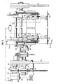
- Figure 1 is a side elevational view of the transfer mechanism and shows the general details thereof including the movement of a blank from a hopper to a discharge position.
- Figure 2 is an elevational view of the mechanism of Figure 1 taken generally along the line 2-2 of Figure 1.
- Figure 3 is a vertical sectional view taken through the transfer mechanism generally along the line 3-3 of Figure 2 and shows the drive for both effecting pivoting of the arm and for rotating the rotatable shaft on which the arm is pivotally mounted.
- Figure 4 is a vertical sectional view taken generally along the line 4-4 of Figure 2 and shows the specific drive for effecting oscillation of the suction head relative to the arm as the arm pivots.
- Referring now to the drawings in detail, reference is first made to Figure 2 wherein there is illustrated two spaced apart
vertical mounting plates mounting plates transverse bearings 14 and 16 in which there is rotatably journalled a transversely extendingrotating shaft 18. Theshaft 18 has rotatably journalled thereonbearings arms arm mounting block 28 which is fixedly secured to a respective one of thebearings block 28 has thearm 24 slidably passing therethrough with the arm being locked in an adjusted position by means of a locking screw 30 (Fig. 2). - The
mounting blocks 28 are joined together by atransverse shaft 32 to which themounting blocks 28 are suitably fixed and so as to space apart themounting blocks 28 and thus thearms - Each
arm pivot shaft 36 which is rotatably journalled relative thereto. Eachpivot shaft 36 carries amounting block 38 of asuction head 40 with the mounting block being offsetto one side of the respective arm, as shown in Figure 2. The mounting block38 issecuredto itsrespective pivot shaft 36 for pivoting therewith and carries a plurality ofsuction cups 42. - Each
arm shaft 44 adjacent its offset end. Each drivenshaft 44 carries for oscillation therewith adrive sprocket 46 which is meshed with a drivensprocket 48 secured to thepivot shaft 36. - The driven
shaft 44 aiso carries a drivenwheel 50 in the form of a sprocket which is coupled to a drive wheel 52, also in the form of a sprocket, by a drive element in the form of achain 54. Each drive wheel 52 is fixedly secured to therotatable shaft 18 for oscillation therewith. - Referring once again to Figure 2, it will be seen that the
mounting plate 10 carries abearing unit 56 in which there is rotatably journalled adrive shaft 58. Thedrive shaft 58 extends through themounting plate 10 and carries on the end thereof adjacent thearm 24 aneccentric drive unit 60 including aneccentric pin 62. Anadjustable link 64 extends between through theeccentric pin 62 and one end of the shaft32. Thus, as theshaft 58 rotates and theeccentric drive member 60 rotates therewith, theadjustable link 64 causes oscillation of the interconnectedarms - The
drive shaft 58 also carries acam 66. Thecam 66 has associated therewith a follower mechanism which includes alever 68 which is pivotally mounted on apivot shaft 70 and carries at the center thereof acam follower 72 which engages thecam 66. Acrank arm 74 is adjustably clamped on one end of therotatable shaft 18 and is connected to a free end of thelever 68 by means of apivotal link 76. If desired, atension spring 78 may be engaged with thelever 68 to retain thecam follower 72 in engagement with the surface of thecam 66. - It will thus be seen that the
rotating shaft 58, when it rotates, serves not only to oscillate thearms suction head 40 relative to the arms. - Referring once again to Figure 4, it will be seen that the mechanism will include a
suitable hopper 80 in which blanks B to be transferred are stored. The bottom blank faces downwardly generally at a 45° angle. The bottom blank, when transferred, will be transferred to a generally horizontal position. During the transfer of a blank from thehopper 80 to, for example, conveyor chains 82 (Fig. 2) of a carton applying mechanism, thearms arms arms arms suction heads 40 will pivot or rotate in the opposite direction. - Reference is now made to Figure 1 with respect to the drive mechanism. The carton applying machine will include a suitable drive from which a
chain 82 is driven in the direction of the arrows in Figure 1. Thechain 82 first passes over an idler sprocket 84 and then over asprocket 86 which is carried by a shaft 88 (Fig. 2). The chain next passes over asprocket 90 fixed to theshaft 58 and finally over anidler sprocket 92 carried by anidler shaft 94. - The
shaft 88, which is rotatably journalled in abearing 96 carried by themounting plate 10 is provided with arotary valve 98 which has afixed housing 100 which is connected to avacuum source 102 by avacuum line 104 and to thesuction head 40 by vacuum lines 106. Thus, thesuction heads 40 are energized in time relation to the rotation of theshaft 58 and thus in timed relation to the pivoting of thearms - Although only a preferred embodiment of the blank transfer mechanism has been specifically illustrated and described herein, it is to be understood that minor variations may be made in the transfer mechanism without departing from the spirit and scope of the invention as defined by the appended claims.
Claims (7)
Applications Claiming Priority (2)
| Application Number | Priority Date | Filing Date | Title |
|---|---|---|---|
| US06/428,901 US4549731A (en) | 1982-09-30 | 1982-09-30 | Carton blank transfer mechanism |
| US428901 | 1982-09-30 |
Publications (2)
| Publication Number | Publication Date |
|---|---|
| EP0105718A1 EP0105718A1 (en) | 1984-04-18 |
| EP0105718B1 true EP0105718B1 (en) | 1987-03-25 |
Family
ID=23700883
Family Applications (1)
| Application Number | Title | Priority Date | Filing Date |
|---|---|---|---|
| EP83305849A Expired EP0105718B1 (en) | 1982-09-30 | 1983-09-28 | Carton blank transfer mechanism |
Country Status (4)
| Country | Link |
|---|---|
| US (1) | US4549731A (en) |
| EP (1) | EP0105718B1 (en) |
| JP (1) | JPS5982237A (en) |
| DE (1) | DE3370459D1 (en) |
Families Citing this family (1)
| Publication number | Priority date | Publication date | Assignee | Title |
|---|---|---|---|---|
| EP0207778A3 (en) * | 1985-07-03 | 1988-06-15 | Portals Engineering Limited | Gathering machine |
Family Cites Families (22)
| Publication number | Priority date | Publication date | Assignee | Title |
|---|---|---|---|---|
| CA479901A (en) * | 1952-01-01 | Dexter Folder Company | Sheet feeding apparatus | |
| FR598302A (en) * | 1925-05-15 | 1925-12-14 | Marinoni Machines Et Materiel | Sheet conveyor separator for automatic feeder or other devices |
| US2566175A (en) * | 1945-05-31 | 1951-08-28 | Danielsson Yngve Aug Ferdinand | Sheet feeding apparatus for printing presses or the like |
| CH272281A (en) * | 1948-04-28 | 1950-12-15 | Neby Treu Unternehmen | Control mechanism of the lifting suction cups in a sheet feeder with rear suction of the sheet to be fed into a graphics machine. |
| FR1049622A (en) * | 1952-01-17 | 1953-12-30 | Suction cup movement for separating a sheet from a stack of sheets | |
| US2808766A (en) * | 1954-05-18 | 1957-10-08 | Delson Candy Company | Carton folding machine |
| US2924156A (en) * | 1954-05-24 | 1960-02-09 | Tech Art Inc | Box setting up machine |
| US2879700A (en) * | 1955-10-24 | 1959-03-31 | United Biscuit Company Of Amer | Cellular tray forming and assembling machine |
| US3005631A (en) * | 1959-01-26 | 1961-10-24 | Lynch Corp | Vacuum card feeder |
| US3053529A (en) * | 1960-02-01 | 1962-09-11 | Memco Machinery Corp | Blank feeding apparatus for box erecting machine |
| US3287011A (en) * | 1962-10-30 | 1966-11-22 | Weyerhaeuser Co | Pneumatic sheet separating and delivery means |
| US3215427A (en) * | 1964-01-03 | 1965-11-02 | Bradford Speed Packaging And D | Devices for storing and feeding folding box blanks |
| US3352215A (en) * | 1964-05-29 | 1967-11-14 | Wainberg Daniel | Feeding mechanism for a container forming machine |
| US3352216A (en) * | 1964-07-01 | 1967-11-14 | Wainberg Daniel | Feeding mechanism for a container forming machine |
| DE6911232U (en) * | 1969-03-20 | 1969-07-17 | Waldrich Werkzeugmasch | CROSSBAR OF A COMBINED MACHINE TOOL, IN PARTICULAR PLANING AND GRINDING MACHINE |
| US4034658A (en) * | 1975-10-28 | 1977-07-12 | Olinkraft, Inc. | Tray feeder system |
| US4097040A (en) * | 1976-10-28 | 1978-06-27 | Stephens Industries, Inc. | Multiple size envelope feeder |
| US4081945A (en) * | 1976-11-15 | 1978-04-04 | The Mead Corporation | Packaging machine for use with cartons of different sizes with minimum adjustment |
| DE2701201A1 (en) * | 1977-01-13 | 1978-07-20 | Agfa Gevaert Ag | Electron radiographic instrument forming latent charged image |
| US4149452A (en) * | 1977-05-04 | 1979-04-17 | Talarico Lawrence J | Folding and packaging machine |
| US4355967A (en) * | 1980-09-30 | 1982-10-26 | The Continental Group, Inc. | Label applying device |
| US4355797A (en) * | 1980-10-06 | 1982-10-26 | Diebold Incorporated | Picker mechanism for automatic banking machines |
-
1982
- 1982-09-30 US US06/428,901 patent/US4549731A/en not_active Expired - Lifetime
-
1983
- 1983-09-28 EP EP83305849A patent/EP0105718B1/en not_active Expired
- 1983-09-28 DE DE8383305849T patent/DE3370459D1/en not_active Expired
- 1983-09-29 JP JP58181753A patent/JPS5982237A/en active Granted
Also Published As
| Publication number | Publication date |
|---|---|
| JPH0348099B2 (en) | 1991-07-23 |
| JPS5982237A (en) | 1984-05-12 |
| US4549731A (en) | 1985-10-29 |
| EP0105718A1 (en) | 1984-04-18 |
| DE3370459D1 (en) | 1987-04-30 |
Similar Documents
| Publication | Publication Date | Title |
|---|---|---|
| US7461838B2 (en) | Spaced apart segment wheel assembly for a carton packaging machine | |
| US5102385A (en) | Feeder mechanism for sleeve type cartons | |
| KR920006489B1 (en) | Carton handle applicator | |
| EP0417868B1 (en) | Paper feeding device | |
| US5771660A (en) | Transverse sealing apparatus for a tubular bag packaging machine | |
| US4697973A (en) | Apparatus and method for handling folded cartons | |
| US4614074A (en) | Apparatus for serially inserting straws into pouches | |
| US5675963A (en) | Mechanism for accumulating a stack of articles and for then dropping the stack | |
| EP0183361B1 (en) | Improvements in or relating to apparatus and methods for feeding articles such as sheets or boards | |
| US3053529A (en) | Blank feeding apparatus for box erecting machine | |
| CA1072592A (en) | Conveying unit for feeding portions of sheet material, particularly preshaped or punched pieces of cardboard or the like, to a user machine, particularly a machine for packaging cigarettes into hinged lid packets | |
| US4478565A (en) | Compact dough dividing and forming machine | |
| US4549731A (en) | Carton blank transfer mechanism | |
| US4928950A (en) | Rotary type feeder machines and methods | |
| US3802280A (en) | Box wrapping machine | |
| GB2157271A (en) | Gauze folding machine | |
| CN214652234U (en) | A feeding mechanism for automatic conveying of printing presses | |
| GB2219991A (en) | Zig-zag folding apparatus | |
| CN117208281A (en) | A quantitative filling and packaging device for rice processing | |
| CN211496291U (en) | Discharging mechanism of bag making machine | |
| US2234069A (en) | Machine for settling and compacting flour in bags | |
| CN211810442U (en) | Sheet sorting device | |
| US1935391A (en) | Blank feeding mechanism | |
| US3306422A (en) | Drive for uprighting boxes | |
| US4070952A (en) | Carton storage, feeding and opening apparatus |
Legal Events
| Date | Code | Title | Description |
|---|---|---|---|
| PUAI | Public reference made under article 153(3) epc to a published international application that has entered the european phase |
Free format text: ORIGINAL CODE: 0009012 |
|
| AK | Designated contracting states |
Designated state(s): DE FR GB |
|
| 17P | Request for examination filed |
Effective date: 19841016 |
|
| GRAA | (expected) grant |
Free format text: ORIGINAL CODE: 0009210 |
|
| AK | Designated contracting states |
Kind code of ref document: B1 Designated state(s): DE FR GB |
|
| REF | Corresponds to: |
Ref document number: 3370459 Country of ref document: DE Date of ref document: 19870430 |
|
| ET | Fr: translation filed | ||
| PLBE | No opposition filed within time limit |
Free format text: ORIGINAL CODE: 0009261 |
|
| STAA | Information on the status of an ep patent application or granted ep patent |
Free format text: STATUS: NO OPPOSITION FILED WITHIN TIME LIMIT |
|
| 26N | No opposition filed | ||
| REG | Reference to a national code |
Ref country code: GB Ref legal event code: IF02 |
|
| PGFP | Annual fee paid to national office [announced via postgrant information from national office to epo] |
Ref country code: FR Payment date: 20020830 Year of fee payment: 20 |
|
| PGFP | Annual fee paid to national office [announced via postgrant information from national office to epo] |
Ref country code: GB Payment date: 20020927 Year of fee payment: 20 |
|
| PGFP | Annual fee paid to national office [announced via postgrant information from national office to epo] |
Ref country code: DE Payment date: 20020930 Year of fee payment: 20 |
|
| PG25 | Lapsed in a contracting state [announced via postgrant information from national office to epo] |
Ref country code: GB Free format text: LAPSE BECAUSE OF EXPIRATION OF PROTECTION Effective date: 20030927 |
|
| REG | Reference to a national code |
Ref country code: GB Ref legal event code: PE20 |