EP0104874B1 - Electrical harness fabrication method and apparatus - Google Patents
Electrical harness fabrication method and apparatus Download PDFInfo
- Publication number
- EP0104874B1 EP0104874B1 EP83305544A EP83305544A EP0104874B1 EP 0104874 B1 EP0104874 B1 EP 0104874B1 EP 83305544 A EP83305544 A EP 83305544A EP 83305544 A EP83305544 A EP 83305544A EP 0104874 B1 EP0104874 B1 EP 0104874B1
- Authority
- EP
- European Patent Office
- Prior art keywords
- connectors
- station
- harnesses
- connecting means
- connector
- Prior art date
- Legal status (The legal status is an assumption and is not a legal conclusion. Google has not performed a legal analysis and makes no representation as to the accuracy of the status listed.)
- Expired
Links
- 238000000034 method Methods 0.000 title claims description 22
- 238000004519 manufacturing process Methods 0.000 title description 3
- 238000009413 insulation Methods 0.000 claims description 21
- 238000006073 displacement reaction Methods 0.000 claims description 14
- 238000005520 cutting process Methods 0.000 claims description 11
- 238000003780 insertion Methods 0.000 description 8
- 230000037431 insertion Effects 0.000 description 8
- 238000003860 storage Methods 0.000 description 1
Images


Classifications
-
- H—ELECTRICITY
- H01—ELECTRIC ELEMENTS
- H01R—ELECTRICALLY-CONDUCTIVE CONNECTIONS; STRUCTURAL ASSOCIATIONS OF A PLURALITY OF MUTUALLY-INSULATED ELECTRICAL CONNECTING ELEMENTS; COUPLING DEVICES; CURRENT COLLECTORS
- H01R43/00—Apparatus or processes specially adapted for manufacturing, assembling, maintaining, or repairing of line connectors or current collectors or for joining electric conductors
- H01R43/01—Apparatus or processes specially adapted for manufacturing, assembling, maintaining, or repairing of line connectors or current collectors or for joining electric conductors for connecting unstripped conductors to contact members having insulation cutting edges
-
- Y—GENERAL TAGGING OF NEW TECHNOLOGICAL DEVELOPMENTS; GENERAL TAGGING OF CROSS-SECTIONAL TECHNOLOGIES SPANNING OVER SEVERAL SECTIONS OF THE IPC; TECHNICAL SUBJECTS COVERED BY FORMER USPC CROSS-REFERENCE ART COLLECTIONS [XRACs] AND DIGESTS
- Y10—TECHNICAL SUBJECTS COVERED BY FORMER USPC
- Y10S—TECHNICAL SUBJECTS COVERED BY FORMER USPC CROSS-REFERENCE ART COLLECTIONS [XRACs] AND DIGESTS
- Y10S439/00—Electrical connectors
- Y10S439/933—Special insulation
- Y10S439/937—Plural insulators in strip form
-
- Y—GENERAL TAGGING OF NEW TECHNOLOGICAL DEVELOPMENTS; GENERAL TAGGING OF CROSS-SECTIONAL TECHNOLOGIES SPANNING OVER SEVERAL SECTIONS OF THE IPC; TECHNICAL SUBJECTS COVERED BY FORMER USPC CROSS-REFERENCE ART COLLECTIONS [XRACs] AND DIGESTS
- Y10—TECHNICAL SUBJECTS COVERED BY FORMER USPC
- Y10T—TECHNICAL SUBJECTS COVERED BY FORMER US CLASSIFICATION
- Y10T29/00—Metal working
- Y10T29/49—Method of mechanical manufacture
- Y10T29/49002—Electrical device making
- Y10T29/49117—Conductor or circuit manufacturing
- Y10T29/49174—Assembling terminal to elongated conductor
-
- Y—GENERAL TAGGING OF NEW TECHNOLOGICAL DEVELOPMENTS; GENERAL TAGGING OF CROSS-SECTIONAL TECHNOLOGIES SPANNING OVER SEVERAL SECTIONS OF THE IPC; TECHNICAL SUBJECTS COVERED BY FORMER USPC CROSS-REFERENCE ART COLLECTIONS [XRACs] AND DIGESTS
- Y10—TECHNICAL SUBJECTS COVERED BY FORMER USPC
- Y10T—TECHNICAL SUBJECTS COVERED BY FORMER US CLASSIFICATION
- Y10T29/00—Metal working
- Y10T29/49—Method of mechanical manufacture
- Y10T29/49002—Electrical device making
- Y10T29/49117—Conductor or circuit manufacturing
- Y10T29/49174—Assembling terminal to elongated conductor
- Y10T29/49181—Assembling terminal to elongated conductor by deforming
-
- Y—GENERAL TAGGING OF NEW TECHNOLOGICAL DEVELOPMENTS; GENERAL TAGGING OF CROSS-SECTIONAL TECHNOLOGIES SPANNING OVER SEVERAL SECTIONS OF THE IPC; TECHNICAL SUBJECTS COVERED BY FORMER USPC CROSS-REFERENCE ART COLLECTIONS [XRACs] AND DIGESTS
- Y10—TECHNICAL SUBJECTS COVERED BY FORMER USPC
- Y10T—TECHNICAL SUBJECTS COVERED BY FORMER US CLASSIFICATION
- Y10T29/00—Metal working
- Y10T29/53—Means to assemble or disassemble
- Y10T29/5313—Means to assemble electrical device
- Y10T29/532—Conductor
- Y10T29/53209—Terminal or connector
- Y10T29/53213—Assembled to wire-type conductor
- Y10T29/53217—Means to simultaneously assemble multiple, independent conductors to terminal
Definitions
- the present invention relates generally to a method and apparatus for fabricating a plurality of electrical harnesses.
- Each harness includes a connector defined by a housing with insulation displacement type contacts loaded therein connected to an insulation clad wire.
- a typical electrical harness that is now widely accepted includes a connector with a housing in which insulation displacement type contacts are positioned. Some or all of the contacts are electrically connected to insulation clad wires that may be of different lengths with different segments of insulation removed from the ends of the wire remote from the connector.
- US-A-4,235,015 discloses a method and apparatus for fabricating an electrical harness of the type described by locating a connector at a position on the apparatus to allow insertion of a plurality of insulation clad wires into corresponding contacts within a single housing, drawing a predetermined length of wire, cutting the wires, forming loops in the wires and removing a portion of the insulation on the wire at the end distant from the connector.
- the apparatus and method as disclosed in US-A-4,235,015 results in the production of a single harness for each cycle of the apparatus. It is highly desirable to produce several harnesses simultaneously since this would be more economical and efficient, particularly for harnesses having relatively few wires.
- a principal object of the present invention to provide an improved method and apparatus for fabricating a plurality of electrical harnesses of the type including at least one connector defined by a housing with insulation displacement type contacts, each contact being connected to an insulation clad wire.
- the method of the present invention is characterised by the steps of (a) forming a set of connectors with the housings of the connectors in the set being joined together by severable connecting means; (b) inserting at least one wire into each said contact in each said housing and (c) severing said severable connecting means to form individual harnesses.
- the method preferably includes the steps of severing said severable connecting means from each of said harnesses and collecting and disposing of said severed connecting means.
- the present invention also provides an apparatus for producing a plurality of electrical harnesses by a method of the present invention wherein each said electrical harness includes a connector defined by a housing with at least one insulation displacement type contact loaded therein, said apparatus comprising a connector feed station defined on said apparatus, means for feeding a set of connectors to said connector feed station wherein said set of connectors includes a plurality of housings joined together by connecting means, a second station defined on said apparatus, means for moving said set of connectors from said connector feed station to said second station, means for inserting a wire into each said insulation displacement type contact, and means for severing said connecting means to define a plurality of independent harnesses.
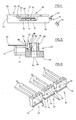
- FIG. 6 illustrating a set of electrical harnesses generally designated by the reference numeral 10'.
- the set 10' of electrical harnesses includes three electrical harnesses 12', 14' and 16' each of which is defined by a housing 18, 20 and 22, respectively, that are chained or joined together by integral connecting tabs 24 and 26 and connected wiring 30.
- the housings 18, 20 and 22 are identical, but the principles of the invention are also applicable to joined sets of differing housings.
- Within each of the insulated housings 18, 20 and 22 there may be positioned a plurality of insulation displacement type contacts (not shown).
- each electrical harness 12', 14' and 16' includes a locking ramp 32 that may be used to lock each electrical harness 12', 14' and 16' onto a P.C. board or similar device; however, it should be understood that this design is not limiting and the locking ramps 32 need not be included.
- the tabs 24 and 26 hold the harnesses 12', 14' and 16' as a unit at predetermined distances from each other allowing insertion of a plurality of wires 30 into the correct contacts in a single operation.
- FIG. 1 there is generally illustrated a connector feed station 34 that is defined on an electrical harness fabricating apparatus.
- the connector feed station 34 sequentially feeds sets 10' of connectors into an elongated track 36 defined in a platform 38. Insulation displacement contacts are preloaded into the housings of the sets 10' of connectors 10.
- the track 36 is of a configuration to accommodate and hold sets of connectors in an upright position and to allow sliding along the track 36.
- the sets 10' of connectors are fed into the track 36 by a feeding means 40 that holds a number of sets of connectors to allow continuous, sequential feeding.
- a moving means generally designated by the reference numeral 42 is actuated by an advancing drive (not shown) to advance the set 10' of connectors to a second, wire insertion station generally designated by the reference numeral 44 ( Figure 2).
- the moving means 42 includes a first member 46 that is a portion of the advancing drive and a connector engaging member 48 secured to member 46 and positioned within track 36 to engage the set 10' of connectors.
- the second station 44 ( Figure 2) includes a carrier 50 that is aligned with track 38 to accept and locate a set 10' of connectors.
- the carrier 50 includes a generally U-shaped connector nest 52 with a central passage 53 and an opening 54 in the bottom thereof.
- Connector insertion pins 56 extend through opening 54 to engage the set 10' of connectors.
- the connector sets 10' are moved upwardly toward an insertion blade 58 and the insulated wires 30 are inserted into the insulation displacement contacts in each connector 12, 14 and 16 in substantially the same manner as disclosed in US-A-4,235,015 and reference to this patent may be made for a more detailed description for this procedure and of other operations which may be carried out such as wire looping, cutting, and insulation stripping.
- the tabs 24 and 26 maintain a fixed spacial relationship between each of the housings 18, 20 and 22 and between all of the slots 28 so that the wire insertion operation can be carried out automatically. Once wires 30 have been inserted within the insulation displacement contacts and any other desired operations have been performed, the connecting tabs 24 and 26 are no longer necessary and are severed completely to free the individual harnesses.
- a carrier drive (not shown) is actuated moving the carrier 50 to a tab removing station on the apparatus generally designated by the reference numeral 60 ( Figures 3, 4 and 5).
- the tab removal station 60 includes a mounting plate 62 on which an extension of the connector nest 52 is secured.
- a portion of the front wall 64 of the connector nest 52 is removed to define an access area generally designated by the reference numeral 66 within which the sets 10' of electrical harnesses are positioned.
- Adjacent to and extending outwardly from the opening 66 is a tab removal or cutting member generally designated by the reference numeral 68.
- the tab removal member 68 includes a base 70 reciprocally mounted within the mounting plate 62 and actuated by a cutting base actuation drive (not shown). On the upper surface of the base 70 are a plurality of cutting members 72 corresponding to the number and position of the tabs 24 and 26.
- the base 70 is reciprocated to advance the cutting members 72 from the position illustrated in Figure 7 to the cutting position illustrated in Figure 8 whereupon the cutting members 72 extend through the opening 66, engage and sever the connecting tabs 24 and 26 and push the connecting tabs 24 and 26 through apertures 74 and 76 in a back wall 80 of the connector nest 52.
- An open top receptacle or container 82 is secured to the mounting plate 62 at a location behind the openings 74 and 76. The container 82 collects the removed tabs 24 and 26 and deposits them through an opening 83 ( Figure 5) for disposal.
- Ejection of the assembled electrical harnesses 12', 14' and 16' is accomplished by an ejection means generally designated by the reference numeral 84 ( Figure 3).
- the ejection means 84 operates in conjunction with a stop mechanism formed by stop member 86 ( Figure 5).
- the stop member 86 is mounted to the carrier 50 for biased pivotal movement such that one end (see in Figure 5) protrudes into the connector receiving channel 53 to prevent backward movement of the sets 10' of connectors during the cutting operation.
- the ejection means 84 includes a base member 88 connected to an ejection drive (not shown) and an ejection pawl 90 pivotally mounted by a pin 92 to the member 88. A distal end 94 of the pawl 90 engages the rear electrical harness 16.
- the ejection drive actuates the ejection assembly 84 to move the individual electrical harnesses 12', 14' and 16' out of the connector nest 52 ( Figure 4).
- the ejection assembly 84 is reciprocated in a rearward direction and thereafter pawl 90 pivots over the next set 10' of connectors inserted into the carrier 50 to return to the original position ( Figure 3).
- the stop member 86 is retracted by the action of the moving means 42 moving each set of connectors 10 to the second, wire insertion station 44, the stop member thereafter being repositioned in the channel 53 by its bias.
- the apparatus and method described with reference to the drawings results in the production of several electrical harnesses during each cycle substantially increasing the efficiency of operation and reducing the cost of the individual electrical harnesses.
- the apparatus and method may be used on several types of electrical harnesses and the configuration and number of electrical harnesses included in each set 10' is not intended to be limited.
Landscapes
- Engineering & Computer Science (AREA)
- Manufacturing & Machinery (AREA)
- Manufacturing Of Electrical Connectors (AREA)
Description
- The present invention relates generally to a method and apparatus for fabricating a plurality of electrical harnesses. Each harness includes a connector defined by a housing with insulation displacement type contacts loaded therein connected to an insulation clad wire.
- Manufacturers of electronic products are relying on electrical harnesses employing insulation displacement type contacts to avoid many of the inefficiencies and costs associated with other types of electrical connections. A typical electrical harness that is now widely accepted includes a connector with a housing in which insulation displacement type contacts are positioned. Some or all of the contacts are electrically connected to insulation clad wires that may be of different lengths with different segments of insulation removed from the ends of the wire remote from the connector.
- Automatic equipment is often employed to fabricate electrical harnesses of the type described. One example of a method and apparatus for fabricating an electrical harness of this type is disclosed in US-A-4,235,015 which issued on November 25, 1980.- Generally, US-A-4,235,015 discloses a method and apparatus for fabricating an electrical harness of the type described by locating a connector at a position on the apparatus to allow insertion of a plurality of insulation clad wires into corresponding contacts within a single housing, drawing a predetermined length of wire, cutting the wires, forming loops in the wires and removing a portion of the insulation on the wire at the end distant from the connector. The apparatus and method as disclosed in US-A-4,235,015 results in the production of a single harness for each cycle of the apparatus. It is highly desirable to produce several harnesses simultaneously since this would be more economical and efficient, particularly for harnesses having relatively few wires.
- It is, therefore, a principal object of the present invention to provide an improved method and apparatus for fabricating a plurality of electrical harnesses of the type including at least one connector defined by a housing with insulation displacement type contacts, each contact being connected to an insulation clad wire.
- The method of the present invention is characterised by the steps of (a) forming a set of connectors with the housings of the connectors in the set being joined together by severable connecting means; (b) inserting at least one wire into each said contact in each said housing and (c) severing said severable connecting means to form individual harnesses.
- The method preferably includes the steps of severing said severable connecting means from each of said harnesses and collecting and disposing of said severed connecting means.
- The present invention also provides an apparatus for producing a plurality of electrical harnesses by a method of the present invention wherein each said electrical harness includes a connector defined by a housing with at least one insulation displacement type contact loaded therein, said apparatus comprising a connector feed station defined on said apparatus, means for feeding a set of connectors to said connector feed station wherein said set of connectors includes a plurality of housings joined together by connecting means, a second station defined on said apparatus, means for moving said set of connectors from said connector feed station to said second station, means for inserting a wire into each said insulation displacement type contact, and means for severing said connecting means to define a plurality of independent harnesses.
- One way of carrying out the present invention in both its method and apparatus aspects is described in detail below by way of example and not by way of limitation with reference to drawings which illustrate one specific embodiment of an apparatus in accordance with the present invention.
- Figure 1 is a perspective view of a connector feed station of the apparatus;
- Figure 2 is a vertical cross-sectional view of a wire insertion station of the apparatus;
- Figure 3 is a perspective view of a severing assembly included in the apparatus;
- Figure 4 is a front, partially cut-away view of the removing assembly illustrated in Figure 3;
- Figure 5 is a view taken generally along line 5-5 of Figure 3;
- Figure 6 Is an enlarged perspective view of a set of electrical harnesses joined by connecting means;
- Figure 7 is a top plan view of the severing assembly illustrated in Figure 3 prior to removal of the connecting means; and
- Figure 8 is a view similar to Figure 7 illustrating the removal of the connecting means.
- With reference to the drawings, in order to depict in an understandable fashion an exemplary method for fabricating electrical harnesses in accordance with the present invention, the exemplary apparatus for fabricating electrical harnesses is illustrated schematically in Figures 1 to 8. For more detailed illustrations and disclosure of portions of the apparatus, reference may be made to US-A-4,235,015.
- To understand the product produced by the apparatus and method which is about to be described, attention is directed first to Figure 6 illustrating a set of electrical harnesses generally designated by the reference numeral 10'. The set 10' of electrical harnesses includes three electrical harnesses 12', 14' and 16' each of which is defined by a
housing tabs wiring 30. In the illustrated arrangement thehousings insulated housings particular housings identical slots 28 and insulatedwires 30 are positioned within eachslot 28 in the insulation displacement type contacts. Iffewer wires 30 are required, the connector may include one or more voids orslots 28 having nowires 30. Each electrical harness 12', 14' and 16' includes alocking ramp 32 that may be used to lock each electrical harness 12', 14' and 16' onto a P.C. board or similar device; however, it should be understood that this design is not limiting and thelocking ramps 32 need not be included. - An important feature of the set 10' of harnesses are the connecting means formed by the
tabs housings tabs wires 30 into the correct contacts in a single operation. - Turning now to Figure 1 there is generally illustrated a
connector feed station 34 that is defined on an electrical harness fabricating apparatus. Theconnector feed station 34 sequentially feeds sets 10' of connectors into anelongated track 36 defined in aplatform 38. Insulation displacement contacts are preloaded into the housings of the sets 10' ofconnectors 10. Thetrack 36 is of a configuration to accommodate and hold sets of connectors in an upright position and to allow sliding along thetrack 36. The sets 10' of connectors are fed into thetrack 36 by a feeding means 40 that holds a number of sets of connectors to allow continuous, sequential feeding. - Once a set 10' of connectors has been positioned in the
track 36, a moving means generally designated by thereference numeral 42 is actuated by an advancing drive (not shown) to advance the set 10' of connectors to a second, wire insertion station generally designated by the reference numeral 44 (Figure 2). The movingmeans 42 includes afirst member 46 that is a portion of the advancing drive and aconnector engaging member 48 secured tomember 46 and positioned withintrack 36 to engage the set 10' of connectors. - The second station 44 (Figure 2) includes a
carrier 50 that is aligned withtrack 38 to accept and locate a set 10' of connectors. Thecarrier 50 includes a generally U-shapedconnector nest 52 with acentral passage 53 and an opening 54 in the bottom thereof.Connector insertion pins 56 extend through opening 54 to engage the set 10' of connectors. The connector sets 10' are moved upwardly toward aninsertion blade 58 and the insulatedwires 30 are inserted into the insulation displacement contacts in eachconnector - The
tabs housings slots 28 so that the wire insertion operation can be carried out automatically. Oncewires 30 have been inserted within the insulation displacement contacts and any other desired operations have been performed, the connectingtabs carrier 50 to a tab removing station on the apparatus generally designated by the reference numeral 60 (Figures 3, 4 and 5). Thetab removal station 60 includes amounting plate 62 on which an extension of theconnector nest 52 is secured. A portion of thefront wall 64 of theconnector nest 52 is removed to define an access area generally designated by thereference numeral 66 within which the sets 10' of electrical harnesses are positioned. Adjacent to and extending outwardly from the opening 66 is a tab removal or cutting member generally designated by thereference numeral 68. Thetab removal member 68 includes abase 70 reciprocally mounted within themounting plate 62 and actuated by a cutting base actuation drive (not shown). On the upper surface of thebase 70 are a plurality of cuttingmembers 72 corresponding to the number and position of thetabs - Once a set 10' of electrical harnesses is positioned within the
open area 66, thebase 70 is reciprocated to advance thecutting members 72 from the position illustrated in Figure 7 to the cutting position illustrated in Figure 8 whereupon thecutting members 72 extend through theopening 66, engage and sever the connectingtabs tabs apertures back wall 80 of theconnector nest 52. An open top receptacle orcontainer 82 is secured to themounting plate 62 at a location behind theopenings container 82 collects the removedtabs tabs receptacle 82, thebase 70 is returned to the original position illustrated in Figure 7. The separate and individual electrical harnesses 12', 14' and 16' may now be ejected from the apparatus for storage or use. - Ejection of the assembled electrical harnesses 12', 14' and 16' is accomplished by an ejection means generally designated by the reference numeral 84 (Figure 3). The ejection means 84 operates in conjunction with a stop mechanism formed by stop member 86 (Figure 5). The
stop member 86 is mounted to thecarrier 50 for biased pivotal movement such that one end (see in Figure 5) protrudes into theconnector receiving channel 53 to prevent backward movement of the sets 10' of connectors during the cutting operation. The ejection means 84 includes abase member 88 connected to an ejection drive (not shown) and anejection pawl 90 pivotally mounted by apin 92 to themember 88. Adistal end 94 of thepawl 90 engages the rearelectrical harness 16. At the completion of the tab cutting operation, the ejection drive actuates theejection assembly 84 to move the individual electrical harnesses 12', 14' and 16' out of the connector nest 52 (Figure 4). Once the fully assembled electrical harnesses 12', 14' and 16' have been ejected from the apparatus, theejection assembly 84 is reciprocated in a rearward direction and thereafterpawl 90 pivots over the next set 10' of connectors inserted into thecarrier 50 to return to the original position (Figure 3). In a similar way thestop member 86 is retracted by the action of the moving means 42 moving each set ofconnectors 10 to the second,wire insertion station 44, the stop member thereafter being repositioned in thechannel 53 by its bias. - The apparatus and method described with reference to the drawings results in the production of several electrical harnesses during each cycle substantially increasing the efficiency of operation and reducing the cost of the individual electrical harnesses. The apparatus and method may be used on several types of electrical harnesses and the configuration and number of electrical harnesses included in each set 10' is not intended to be limited.
Claims (11)
Applications Claiming Priority (2)
| Application Number | Priority Date | Filing Date | Title |
|---|---|---|---|
| US422867 | 1982-09-24 | ||
| US06/422,867 US4492023A (en) | 1982-09-24 | 1982-09-24 | Electrical harness fabrication method and apparatus |
Publications (3)
| Publication Number | Publication Date |
|---|---|
| EP0104874A2 EP0104874A2 (en) | 1984-04-04 |
| EP0104874A3 EP0104874A3 (en) | 1984-05-09 |
| EP0104874B1 true EP0104874B1 (en) | 1987-01-21 |
Family
ID=23676755
Family Applications (1)
| Application Number | Title | Priority Date | Filing Date |
|---|---|---|---|
| EP83305544A Expired EP0104874B1 (en) | 1982-09-24 | 1983-09-21 | Electrical harness fabrication method and apparatus |
Country Status (4)
| Country | Link |
|---|---|
| US (1) | US4492023A (en) |
| EP (1) | EP0104874B1 (en) |
| JP (1) | JPS5975507A (en) |
| DE (1) | DE3369438D1 (en) |
Families Citing this family (29)
| Publication number | Priority date | Publication date | Assignee | Title |
|---|---|---|---|---|
| JPS60124375A (en) | 1983-11-28 | 1985-07-03 | モレツクス・インコ−ポレ−テツド | Method and device for constantly polarizing connector |
| US4653183A (en) * | 1984-02-13 | 1987-03-31 | Molex Incorporated | Electrical harnesses |
| US4590650A (en) * | 1984-02-27 | 1986-05-27 | Molex Incorporated | Electrical harness fabrication machine |
| GB8429512D0 (en) * | 1984-11-22 | 1985-01-03 | Molex Inc | Assembling electrical harnesses |
| US4617732A (en) * | 1984-12-31 | 1986-10-21 | Thomas & Betts Corporation | Method for termination of flat cable |
| JPS61181079A (en) * | 1985-02-04 | 1986-08-13 | モレツクス インコ−ポレ−テツド | Electric connector for module construction |
| US4655517A (en) * | 1985-02-15 | 1987-04-07 | Crane Electronics, Inc. | Electrical connector |
| US4660279A (en) * | 1985-05-24 | 1987-04-28 | Molex Incorporated | Apparatus for electrical harness manufacture |
| US4614143A (en) * | 1985-09-20 | 1986-09-30 | Molex Incorporated | Apparatus for providing commoning connectors |
| US4824394A (en) * | 1986-04-10 | 1989-04-25 | Ohio Associated Enterprises, Inc. | IDC connectors with rotated conductor pairs and strain relief base molded onto cable |
| FR2614754B1 (en) * | 1987-04-29 | 1991-07-26 | Labinal | ASSEMBLY OF HOUSING ELEMENTS FOR PRODUCING WIRING HARNESSES |
| US4754865A (en) * | 1987-05-21 | 1988-07-05 | Molex Incorporated | Connector transfer system |
| GB8805474D0 (en) * | 1988-03-08 | 1988-04-07 | Amp Italia | Method of operating harness making machines |
| JPH01137091U (en) * | 1988-03-12 | 1989-09-19 | ||
| FR2631490A1 (en) * | 1988-05-10 | 1989-11-17 | Amp France | COMPOSITE ELECTRICAL CONNECTOR AND METHOD OF LOADING CONDUCTORS INTO THE CONNECTOR |
| US5156557A (en) * | 1990-11-06 | 1992-10-20 | Yazaki Corporation | Electrical interconnection assembly, process of and apparatus for manufacturing the same and wire laying jig therefor |
| GB2278074B (en) * | 1990-11-06 | 1995-03-08 | Yazaki Corp | Electrical interconnection assembly |
| US5186645A (en) * | 1991-10-29 | 1993-02-16 | Molex Incorporated | Electrical connector latching system |
| US5205033A (en) * | 1992-02-27 | 1993-04-27 | At&T Bell Laboratories | Tool for assembling multiple conductor connectors |
| JP3209444B2 (en) * | 1992-04-07 | 2001-09-17 | タイコエレクトロニクスアンプ株式会社 | Wiring device for electrical connector |
| US5471741A (en) * | 1994-10-17 | 1995-12-05 | Molex Incorporated | Wire harness termination apparatus |
| US5509201A (en) * | 1994-10-17 | 1996-04-23 | Molex Incorporated | Wire position shifting mechanism and method of assembling wire harnesses |
| JP3179996B2 (en) * | 1995-02-09 | 2001-06-25 | 矢崎総業株式会社 | Method for manufacturing press-fit joint connector and method for press-fitting electric wire |
| JP3632937B2 (en) * | 1996-05-20 | 2005-03-30 | 矢崎総業株式会社 | Harness manufacturing method, pressure welding machine, connector holding rod and pressure welding device |
| JP3395550B2 (en) * | 1996-11-22 | 2003-04-14 | 矢崎総業株式会社 | Pressure welding apparatus and harness manufacturing method |
| US6612026B1 (en) * | 1999-05-24 | 2003-09-02 | Sumitomo Wiring Systems, Ltd. | Process for mounting terminals with electric wires in cavities of connector housings |
| US20020076990A1 (en) * | 2000-12-15 | 2002-06-20 | Sumitomo Wiring Systems Ltd. | Apparatus for processing a stacked-type connector of a wire harness, a housing holder, apparatus and method and for stacking housings of a stacked-type connectors, and apparatus for pressing a joint portion of stacked-type connector |
| US6827615B2 (en) * | 2001-06-01 | 2004-12-07 | Panduit Corp. | Terminal carrier cut-off design |
| US6585827B2 (en) * | 2001-07-30 | 2003-07-01 | Tennant Company | Apparatus and method of use for cleaning a hard floor surface utilizing an aerated cleaning liquid |
Family Cites Families (9)
| Publication number | Priority date | Publication date | Assignee | Title |
|---|---|---|---|---|
| US3550856A (en) * | 1968-07-03 | 1970-12-29 | Amp Inc | Electrical connector feed strip assembly |
| US4055889A (en) * | 1976-02-18 | 1977-11-01 | Molex Incorporated | Connector harness assembly machine |
| JPS5358657A (en) * | 1976-11-06 | 1978-05-26 | Murata Manufacturing Co | Method of making electric parts having projected discclike substrate |
| US4178675A (en) * | 1978-04-12 | 1979-12-18 | Amp Incorporated | Applicator for telephone connectors |
| CA1133436A (en) * | 1978-09-22 | 1982-10-12 | Burndy Corporation | Spring-locked concatenation of housings for electrical connections |
| US4235015A (en) * | 1979-02-16 | 1980-11-25 | Molex Incorporated | Electrical harness fabrication method and apparatus |
| AU542680B2 (en) * | 1980-03-31 | 1985-03-07 | Amp Incorporated | Wired electrical connectors |
| US4363167A (en) * | 1980-08-11 | 1982-12-14 | Amp Incorporated | Method of terminating leading ends of a plurality of wires |
| JPS5738510A (en) * | 1980-08-19 | 1982-03-03 | Molex Inc | Method of producing electric harness |
-
1982
- 1982-09-24 US US06/422,867 patent/US4492023A/en not_active Expired - Lifetime
-
1983
- 1983-09-19 JP JP58171435A patent/JPS5975507A/en active Pending
- 1983-09-21 DE DE8383305544T patent/DE3369438D1/en not_active Expired
- 1983-09-21 EP EP83305544A patent/EP0104874B1/en not_active Expired
Also Published As
| Publication number | Publication date |
|---|---|
| EP0104874A2 (en) | 1984-04-04 |
| JPS5975507A (en) | 1984-04-28 |
| EP0104874A3 (en) | 1984-05-09 |
| US4492023A (en) | 1985-01-08 |
| DE3369438D1 (en) | 1987-02-26 |
Similar Documents
| Publication | Publication Date | Title |
|---|---|---|
| US4492023A (en) | Electrical harness fabrication method and apparatus | |
| EP0706242B1 (en) | Method and apparatus for manufacturing a wire crimping receptacle connector | |
| US6662444B2 (en) | Method and apparatus of manufacturing wiring harness | |
| US4026629A (en) | Method of manufacturing an electrical harness and electrical connectors and terminals for carrying out the method | |
| EP0720180B1 (en) | Wire assembly apparatus and method for assembling wires | |
| EP0330366B1 (en) | Method and apparatus for terminating flexible wires | |
| US6640425B1 (en) | Apparatus for producing wire harnesses for automotive vehicles | |
| US5125154A (en) | Automated termination station and method of using same | |
| EP0206464B1 (en) | Electrical harness fabrication apparatus | |
| CA1188080A (en) | Method of, and apparatus for, producing wired electrical connectors | |
| EP0708507A2 (en) | Wire harness termination apparatus | |
| US4561155A (en) | Cord manufacturing apparatus and connector attachment machine therefor | |
| IE54549B1 (en) | A method of, and apparatus for, terminating an electrical conductor to an electrical connector | |
| US4754536A (en) | Apparatus and method for connectors of varying dimensions | |
| JPH02299181A (en) | Electric connector device and its insulated bitetype terminal | |
| US4043032A (en) | Terminal applicator apparatus for terminals in strip form | |
| US4653187A (en) | Connector fabrication method and apparatus | |
| JP3125014B2 (en) | Wire crimping harness manufacturing equipment | |
| US4921440A (en) | Connector aggregate | |
| US4060890A (en) | Method of manufacturing an electrical harness | |
| US4258469A (en) | Apparatus and method for installing electrical connectors | |
| EP0418993B1 (en) | Continuous molded electronic component assembly | |
| JP2769247B2 (en) | Manufacturing method of wire crimping harness | |
| EP0280396B1 (en) | Semi-automatic electrical harness fabricating apparatus and method | |
| US4850905A (en) | Strip of electrical contacts |
Legal Events
| Date | Code | Title | Description |
|---|---|---|---|
| PUAI | Public reference made under article 153(3) epc to a published international application that has entered the european phase |
Free format text: ORIGINAL CODE: 0009012 |
|
| PUAL | Search report despatched |
Free format text: ORIGINAL CODE: 0009013 |
|
| AK | Designated contracting states |
Designated state(s): DE FR GB IT |
|
| AK | Designated contracting states |
Designated state(s): DE FR GB IT |
|
| 17P | Request for examination filed |
Effective date: 19840625 |
|
| ITF | It: translation for a ep patent filed | ||
| GRAA | (expected) grant |
Free format text: ORIGINAL CODE: 0009210 |
|
| AK | Designated contracting states |
Kind code of ref document: B1 Designated state(s): DE FR GB IT |
|
| REF | Corresponds to: |
Ref document number: 3369438 Country of ref document: DE Date of ref document: 19870226 |
|
| ET | Fr: translation filed | ||
| PLBE | No opposition filed within time limit |
Free format text: ORIGINAL CODE: 0009261 |
|
| STAA | Information on the status of an ep patent application or granted ep patent |
Free format text: STATUS: NO OPPOSITION FILED WITHIN TIME LIMIT |
|
| 26N | No opposition filed | ||
| REG | Reference to a national code |
Ref country code: FR Ref legal event code: TP |
|
| ITTA | It: last paid annual fee | ||
| PGFP | Annual fee paid to national office [announced via postgrant information from national office to epo] |
Ref country code: GB Payment date: 19980806 Year of fee payment: 16 |
|
| PGFP | Annual fee paid to national office [announced via postgrant information from national office to epo] |
Ref country code: FR Payment date: 19980902 Year of fee payment: 16 |
|
| PGFP | Annual fee paid to national office [announced via postgrant information from national office to epo] |
Ref country code: DE Payment date: 19980928 Year of fee payment: 16 |
|
| PG25 | Lapsed in a contracting state [announced via postgrant information from national office to epo] |
Ref country code: GB Free format text: LAPSE BECAUSE OF NON-PAYMENT OF DUE FEES Effective date: 19990921 |
|
| GBPC | Gb: european patent ceased through non-payment of renewal fee |
Effective date: 19990921 |
|
| PG25 | Lapsed in a contracting state [announced via postgrant information from national office to epo] |
Ref country code: FR Free format text: LAPSE BECAUSE OF NON-PAYMENT OF DUE FEES Effective date: 20000531 |
|
| PG25 | Lapsed in a contracting state [announced via postgrant information from national office to epo] |
Ref country code: DE Free format text: LAPSE BECAUSE OF NON-PAYMENT OF DUE FEES Effective date: 20000701 |
|
| REG | Reference to a national code |
Ref country code: FR Ref legal event code: ST |