EP0104360A2 - Electromagnetic driving tool - Google Patents
Electromagnetic driving tool Download PDFInfo
- Publication number
- EP0104360A2 EP0104360A2 EP83107492A EP83107492A EP0104360A2 EP 0104360 A2 EP0104360 A2 EP 0104360A2 EP 83107492 A EP83107492 A EP 83107492A EP 83107492 A EP83107492 A EP 83107492A EP 0104360 A2 EP0104360 A2 EP 0104360A2
- Authority
- EP
- European Patent Office
- Prior art keywords
- hollow cylinder
- plunger
- valve flap
- tappet
- wrapping device
- Prior art date
- Legal status (The legal status is an assumption and is not a legal conclusion. Google has not performed a legal analysis and makes no representation as to the accuracy of the status listed.)
- Granted
Links
Images
Classifications
-
- B—PERFORMING OPERATIONS; TRANSPORTING
- B25—HAND TOOLS; PORTABLE POWER-DRIVEN TOOLS; MANIPULATORS
- B25C—HAND-HELD NAILING OR STAPLING TOOLS; MANUALLY OPERATED PORTABLE STAPLING TOOLS
- B25C1/00—Hand-held nailing tools; Nail feeding devices
- B25C1/06—Hand-held nailing tools; Nail feeding devices operated by electric power
Definitions
- the invention is based on a wrapping device according to the type of the main claim.
- Such an impact device is already known, in which, after the tappet has been hammered in, a spring is used to return it to its starting position.
- a rubber buffer catches the returning plunger at the end of its return.
- This has the disadvantage that the energy stored when the plunger is intercepted by the rubber buffer often throws the plunger back so far in its working direction that an impact knife connected to it detaches the next available fastening means from the magazine and transports it a little way into the guide channel to the impact point. Only then does the tappet come to rest in its end position on the rubber buffer.
- the impact knife releases another fastener from the magazine, which strikes the fastener already in the guide channel. This is how malfunctions are caused.
- a buffer system intended to destroy excess impact energy according to EU patent application 0054782 could possibly remedy this.
- This buffer system is relatively complex, takes up a lot of space and wears out relatively quickly. This makes it necessary to replace the buffer element, which also requires appropriate structural precaution and careful maintenance of the device.
- the wrapping device according to the invention with the characterizing features of the main claim has the advantage that its air damper is simply the same in construction and in life as the other components of the device. In addition, less space is required for this air damper.
- the combination of the air damper with the check valve ensures an ideal working cycle of undamped impact movement and damped return stroke.
- the measures listed in the subclaims permit advantageous developments and improvements of the wrapping device specified in the main claim.
- the design of the air damper as a tappet guide is particularly advantageous. This saves additional guide parts.
- the design with a hollow cylinder onto which a cup-shaped tappet is pushed results in an ideal damping characteristic with a damping effect that increases towards the end of the return stroke movement.
- FIG. 1 An embodiment of the subject of the invention is shown in the drawing and explained in more detail in the following description.
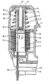
- the figure shows a longitudinal cut through an impact device according to the invention.
- a coil 2 is arranged through the cylindrical interior 3 of which a cup-shaped tappet 4 and a pusher knife 5 fixedly connected thereto are displaceably guided.
- the plunger 4 is additionally axially displaceable on a hollow cylinder 6.
- the widened base 7 of the hollow cylinder 6 is firmly connected to the device housing 1.
- An opening 8 in the device housing 1 connects the interior of the hollow cylinder 6 with the outside air.
- a valve flap 9 is fastened in such a way that it allows air flowing in from the outside to pass freely, but prevents the air from escaping from the housing.
- the space around the plunger 4 is also vented to the outside, which is represented by an opening 10 in the device housing 1.
- a conical coil spring 11 is supported against a spring ring 12 at the end of the plunger 4 and a washer 13 slid onto the plunger 4 in front of it.
- the abutment for this helical spring 11 is formed by a rib 14 of the device housing 1.
- the lower end of the impact knife 5 in the drawing is guided in a guide channel 15.
- a magazine guide 16 for a fastener magazine 17 leads at right angles to the guide channel 15.
- a fastening means is introduced into the guide channel 15 in front of the butt knife 5.
- the tappet 4 When a voltage pulse is applied to the coil 2, the tappet 4 is quickly drawn into the interior 3 of the coil by the resulting magnetic field (arrow 18).
- the butt knife 5 is moved through the guide channel 15, detaches a fastener from the fastener magazine 17 and drives it into a workpiece lying in front of the end of the guide channel 15.
- the tappet 4 sucked in outside air through the opening 8 and the interior of the hollow cylinder 6, the valve flap 9 allowing this outside air to enter unhindered.
- the impact movement was therefore not hindered by the air damper formed from the plunger 4 and the hollow cylinder 6.
- the magnetic field which collapses at the end of the voltage pulse releases the plunger 4 again, so that it can be moved back into its starting position under the action of the helical spring 11.
- the air in the interior of the plunger 4 is slowly pressed through a throttle gap 19 formed between the plunger 4 and the hollow cylinder 6, because the valve flap 9, which now closes the interior of the hollow cylinder 6, does not permit unhindered escape of the air to the outside.
- the return stroke movement in the direction of an arrow 20 is damped and prevents the plunger 4 from rebounding from its contact surface on the base 7 of the hollow cylinder 6. This ensures that the wrapping device functions properly.
Abstract
Es wird ein elektromagnetisch betriebenes Einschlaggerät vorgeschlagen, bei dem die Rückbewegung eines zum Einschlagen magnetisch bewegten Stößels (4) in seine Ruhestellung, durch einen mit einem Rückschlagventil (9) kombinierten Luftdämpfer (4, 6) gedämpft wird. Ein in das Innere des Gerätegehäuses (1) ragender Hohlzylinder (6) ist durch eine Öffnung (8) im Gerätegehäuse (1) mit der Außenluft verbunden und an seinem inneren Ende durch eine zum Gehäuseinneren hin abhebbare Ventilklappe (9) verschlossen. Der Hohlzylinder (6) dient als Führungsstange für den auf ihn aufgeschobenen, topfförmigen Stößel (4). Zwischen dem Hohlzylinder (6) und dem Stößel (4) ist ein Drosselspalt (19) vorgesehen. Der Drosselspalt (19) ist vorzugsweise so gestaltet, daß er sich gegen die Ruhelage ders Stößels (4) hin verengt. Auf diese Weise wird ein Zurückprellen des Stößels (4) und das unbeabsichtigte Lösen eines Befestigungsmittels aus dem Befestigunsmittelmagazin (17) und die sich daraus ergebende Betriebsstörung sicher vermieden.An electromagnetically driven impact device is proposed, in which the return movement of a plunger (4) that is magnetically moved to impact into its rest position is dampened by an air damper (4, 6) combined with a check valve (9). A hollow cylinder (6) projecting into the interior of the device housing (1) is connected to the outside air through an opening (8) in the device housing (1) and is closed at its inner end by a valve flap (9) that can be lifted off towards the interior of the device. The hollow cylinder (6) serves as a guide rod for the pot-shaped plunger (4) pushed onto it. A throttle gap (19) is provided between the hollow cylinder (6) and the tappet (4). The throttle gap (19) is preferably designed so that it narrows towards the rest position of the tappet (4). In this way, a rebound of the plunger (4) and the unintentional loosening of a fastener from the fastener magazine (17) and the resulting malfunction are reliably avoided.
Description
Die Erfindung geht aus von einem Einschlaggerät nach-der Gattung des Hauptanspruchs. Es ist schon ein solches Einschlaggerät bekannt,-bei dem nach dem Einschlagen der Stößel mittels einer Feder in seine Ausgangsstellung zurückgeführt wird. Ein Gummipuffer fängt den zurückkehrenden Stößel am Ende seines Rückweges ab. Daran ist nachteilig, daß die beim Abfangen des Stößels vom Gummipuffer gespeicherte Energie oftmals den Stößel soweit in seine Arbeitsrichtung zurückwirft, daß ein mit ihm verbundenes Stoßmesser das nächste vorliegende Befestigungsmittel vom Magazin löst und ein Stück weit in den Führungskanal zur Einschlagstelle hin transportiert. Erst danach kommt der Stößel schließlich in seiner Endlage am Gummipuffer zur Ruhe. Beim nächsten Einschlaghub des Stößels löst das Stoßmesser ein weiteres Befestigungsmittel vom Magazin, das auf das bereits im Führungskanal befindliche Befestigungsmittel stößt. So werden Betriebsstörungen verursacht.The invention is based on a wrapping device according to the type of the main claim. Such an impact device is already known, in which, after the tappet has been hammered in, a spring is used to return it to its starting position. A rubber buffer catches the returning plunger at the end of its return. This has the disadvantage that the energy stored when the plunger is intercepted by the rubber buffer often throws the plunger back so far in its working direction that an impact knife connected to it detaches the next available fastening means from the magazine and transports it a little way into the guide channel to the impact point. Only then does the tappet come to rest in its end position on the rubber buffer. During the next stroke of the ram, the impact knife releases another fastener from the magazine, which strikes the fastener already in the guide channel. This is how malfunctions are caused.
Ein zum Vernichten überschüssiger Schlagenergie nach der EU-Patentanmeldung 0054782 vorgesehenes Puffersystem könnte hier eventuell Abhilfe schaffen. Dieses Puffersystem ist aber verhältnismäßig aufwendig, braucht viel Raum und verschleißt verhältnismäßig schnell. Dies macht das Auswechseln des Pufferelementes erforderlich, wofür ebenfalls entsprechende konstruktive Vorsorge und sorgfältige Wartung des Gerätes erforderlich sind.A buffer system intended to destroy excess impact energy according to EU patent application 0054782 could possibly remedy this. This buffer system is relatively complex, takes up a lot of space and wears out relatively quickly. This makes it necessary to replace the buffer element, which also requires appropriate structural precaution and careful maintenance of the device.
Das erfindungsgemäße Einschlaggerät mit den kennzeichnenden Merkmalen des Hauptanspruchs hat demgegenüber den Vorteil, daß sein Luftdämpfer einfach im Aufbau und in der Lebensdauer den übrigen Bauteilen des Gerätes gleich ist. Außerdem wird für diesen Luftdämpfer weniger Raum benötigt. Durch die Kombination des Luftdämpfers mit dem Rückschlagventil wird ein idealer Arbeitszyklus aus ungedämpfter Einschlagbewegung und gedämpften Rückhub gewährleistet.The wrapping device according to the invention with the characterizing features of the main claim has the advantage that its air damper is simply the same in construction and in life as the other components of the device. In addition, less space is required for this air damper. The combination of the air damper with the check valve ensures an ideal working cycle of undamped impact movement and damped return stroke.
Durch die in den Unteransprüchen aufgeführten Maßnahmen sind vorteilhafte Weiterbildungen und Verbesserungen des im Hauptanspruch angegebenen Einschlaggerätes möglich. Besonders vorteilhaft ist die Ausbildung des Luftdämpfers zugleich als Stößelführung. Das erspart zusätzliche Führungsteile. Zusätzlich ergibt sich in der Ausbildung mit einem Hohlzylinder auf den ein topfförmig gestalteter Stößel aufgeschoben ist, eine ideale Dämpfungscharakteristik mit gegen das Ende der Rückhubbewegung wachsender Dämpferwirkung.The measures listed in the subclaims permit advantageous developments and improvements of the wrapping device specified in the main claim. The design of the air damper as a tappet guide is particularly advantageous. This saves additional guide parts. In addition, the design with a hollow cylinder onto which a cup-shaped tappet is pushed results in an ideal damping characteristic with a damping effect that increases towards the end of the return stroke movement.
Ein Ausführungsbeispiel des Erfindungsgegenstandes ist in der Zeichnung dargestellt und in der nachfolgenden Beschreibung näher erläutert. Die Figur zeigt einen Längsschnitt durch ein erfindungsgemäßes Einschlaggerät.An embodiment of the subject of the invention is shown in the drawing and explained in more detail in the following description. The figure shows a longitudinal cut through an impact device according to the invention.
In einem Gerätegehäuse 1 eines Einschlaggerätes ist eine Spule 2 angeordnet durch deren zylindrischen Innenraum 3 ein topfförmiger Stößel 4 und ein mit diesem fest verbundenes Stoßmesser 5 verschiebbar geführt ist. Der Stößel 4 lagert zusätzlich axial verschiebbar auf einem Hohlzylinder 6. Der verbreiterte Fuß 7 des Hohlzylinders 6 ist fest verbunden mit dem Gerätegehäuse 1. Eine Öffnung 8 im ist Gerätegehäuse 1 verbindet den Innenraum des Hohlzylinders 6 mit der Außenluft. Am gehäuseinneren Ende des Hohlzylinders 6 ist eine Ventilklappe 9 so befestigt, daß sie von außen einströmende Luft ungehindert durchläßt, den Luftaustritt aus dem Gehäuse aber verhindert. Der Raum um den Stößel 4 herum ist ebenfalls nach außen hin entlüftet, was durch eine Öffnung 10 im Gerätegehäuse 1 dargestellt ist. Eine konische Schraubenfeder 11 stützt sich gegen einen Federring 12 am Ende des Stößels 4 und eine davor auf den Stößel 4 aufgeschobene Scheibe 13 ab. Das Widerlager für diese Schraubenfeder 11 wird durch eine Rippe 14 des Gerätegehäuses 1 gebildet. Das in der Zeichnung untere Ende des Stoßmessers 5 ist in einem Führungskanal 15 geführt. Eine Magazinführung 16 für ein Befestigungsmittelmagazin 17 führt rechtwinklig zum Führungskanal 15 hin. So ist in an sich bekannter Weise jeweils ein Befestigungsmittel vor das Stoßmesser 5 in den Führungskanal 15 eingebracht.In a device housing 1 of a wrapping device, a coil 2 is arranged through the
Beim Anlegen eines Spannungsimpulses an die Spule 2 wird durch das entstehende Magnetfeld der Stößel 4 schnell in den Innenraum 3 der Spule hineingezogen (Pfeil 18). Dabei wird das Stoßmesser 5 durch den Führungskanal 15 bewegt, löst ein Befestigungsmittel vom Befestigungsmittelmagazin 17 und treibt dieses in ein vor dem Ende des Führungskanals 15 liegendes Werkstück ein. Bei dieser Bewegung hat der Stößel 4 durch die Öffnung 8 und den Innenraum des Hohlzylinders 6 Außenluft angesaugt, wobei die Ventilklappe 9 diese Außenluft ungehindert eintreten ließ. Die Einschlagbevegung wurde also durch den aus dem Stößel 4 und dem Hohlzylinder 6 gebildeten Luftdämpfer nicht behindert. Das am Ende des Spannungsimpulses zusammenbrechende Magnetfeld gibt den Stößel 4 wieder frei, so daß dieser unter der Wirkung der Schraubenfeder 11 in seine Ausgangsstellung zurückbewegt werden kann. Dabei wird die im Innenraum des Stößels 4 befindliche Luft langsam durch einen zwischen dem Stößel 4 und dem Hohlzylinder 6 gebildeten Drosselspalt 19 gepreßt, weil die nun den Innenraum des Hohlzylinders 6 verschließende Ventilklappe 9 ein unbehindertes Entweichen der Luft nach außen nicht zuläßt. Die Rückhubbewegung in Richtung eines Pfeiles 20 erfolgt gedämpft und verhindert ein Zurückprellen des Stößels 4 von seiner Anlagefläche am Fuß 7 des Hohlzylinders 6. Damit ist eine einwandfreie Funktion des Einschlaggerätes gewährleistet.When a voltage pulse is applied to the coil 2, the tappet 4 is quickly drawn into the
Claims (8)
Applications Claiming Priority (2)
| Application Number | Priority Date | Filing Date | Title |
|---|---|---|---|
| DE3232120 | 1982-08-28 | ||
| DE19823232120 DE3232120A1 (en) | 1982-08-28 | 1982-08-28 | ELECTROMAGNETICALLY OPERATED IMPACT DEVICE |
Publications (3)
| Publication Number | Publication Date |
|---|---|
| EP0104360A2 true EP0104360A2 (en) | 1984-04-04 |
| EP0104360A3 EP0104360A3 (en) | 1985-07-03 |
| EP0104360B1 EP0104360B1 (en) | 1987-10-28 |
Family
ID=6171976
Family Applications (1)
| Application Number | Title | Priority Date | Filing Date |
|---|---|---|---|
| EP83107492A Expired EP0104360B1 (en) | 1982-08-28 | 1983-07-29 | Electromagnetic driving tool |
Country Status (5)
| Country | Link |
|---|---|
| US (1) | US4515303A (en) |
| EP (1) | EP0104360B1 (en) |
| JP (1) | JPS5959361A (en) |
| BR (1) | BR8304632A (en) |
| DE (2) | DE3232120A1 (en) |
Cited By (5)
| Publication number | Priority date | Publication date | Assignee | Title |
|---|---|---|---|---|
| FR2571294A1 (en) * | 1984-10-09 | 1986-04-11 | Bosch Gmbh Robert | ELECTROMAGNETIC SHIFTING APPARATUS COMPRISING A PNEUMATIC SHOCK ABSORBER |
| FR2583715A1 (en) * | 1985-06-12 | 1986-12-26 | Lai Wen Tah | INCREASED IMPACT FORCE STAPLER, COMPRISING A DEVICE ABSORBING THE REBOUNDING STRENGTH |
| DE102004008959A1 (en) * | 2004-02-24 | 2005-09-08 | Aplus Pneumatic Corp. | Nail tacker for nails comprises a magazine containing nails and a nail driver for closing the nails from the magazine |
| WO2015169167A1 (en) * | 2014-05-05 | 2015-11-12 | 北京大风时代科技有限责任公司 | Electromagnetic nail gun |
| CN105451944A (en) * | 2013-07-31 | 2016-03-30 | 日立工机株式会社 | Driving-in machine |
Families Citing this family (17)
| Publication number | Priority date | Publication date | Assignee | Title |
|---|---|---|---|---|
| DE3405906A1 (en) * | 1984-02-18 | 1985-08-22 | Robert Bosch Gmbh, 7000 Stuttgart | DRIVING DEVICE FOR FASTENING AGENTS, ESPECIALLY ELECTROTACKER |
| US4940177A (en) * | 1988-12-30 | 1990-07-10 | Jimena Carlos L | Electric stapler having electronic control circuit |
| GB2275227B (en) * | 1993-02-23 | 1996-11-13 | Tohoku Ricoh Co Limited | Stencil duplication machine |
| DE19728176A1 (en) * | 1997-07-02 | 1999-01-07 | Hilti Ag | High pressure gas operated fitting tool |
| AU2001285301A1 (en) | 2000-08-25 | 2002-03-04 | John P. Barber | Impact device |
| US6783051B2 (en) * | 2002-01-15 | 2004-08-31 | The Fletcher-Terry Company | Point driver |
| US20040159695A1 (en) * | 2002-08-23 | 2004-08-19 | Chu-Kuo Wang | Nail stapler |
| US6742691B2 (en) * | 2002-08-23 | 2004-06-01 | Mu-Yu Chen | Nail stapler |
| US6662990B1 (en) * | 2003-01-03 | 2003-12-16 | Modern Pioneer Ltd. | Buffer apparatus of electrical nailing gun |
| CN2644112Y (en) * | 2003-07-04 | 2004-09-29 | 益卓有限公司 | Electric nail fixer |
| US6857549B1 (en) * | 2003-11-21 | 2005-02-22 | Navtor Technology Corporation | Nail driving gun with a shock-absorbing member |
| US7503400B2 (en) * | 2004-01-30 | 2009-03-17 | Arrow Fastener Co., Inc. | Two shot power nailer |
| GB2411143B (en) * | 2004-02-19 | 2005-12-28 | Aplus Pneumatic Corp | Nail stapler |
| US9071120B2 (en) * | 2011-07-19 | 2015-06-30 | Kanzaki Kokyukoki Mfg. Co., Ltd. | Linear actuator and boring device |
| WO2014156470A1 (en) | 2013-03-29 | 2014-10-02 | 日立工機株式会社 | Driving machine |
| WO2022159538A1 (en) | 2021-01-20 | 2022-07-28 | Milwaukee Electric Tool Corporation | Powered fastener driver |
| US20230081812A1 (en) * | 2021-09-15 | 2023-03-16 | Robert Bosch Gmbh | Head Valve System for Air Spring Power Tool |
Citations (4)
| Publication number | Priority date | Publication date | Assignee | Title |
|---|---|---|---|---|
| GB920586A (en) * | 1960-09-21 | 1963-03-06 | Bourcier Carbon Christian | Improvements in or relating to pneumatic shock absorbers |
| US3434026A (en) * | 1966-12-12 | 1969-03-18 | Fastener Corp | Electrically operated reciprocating tool |
| DE2729002A1 (en) * | 1977-06-28 | 1979-01-11 | Mueller E Gmbh & Co | Nail or staple driver operating from mains supply - has double coils energised in same direction by thyristors |
| FR2405119A1 (en) * | 1978-02-23 | 1979-05-04 | Swingline Inc | Magnetic field actuated portable fastener driver - has axially moving solenoid with tools imparting several impacts on one fastener (NL 6.4.79) |
Family Cites Families (4)
| Publication number | Priority date | Publication date | Assignee | Title |
|---|---|---|---|---|
| US1853695A (en) * | 1930-02-25 | 1932-04-12 | Clarence M Griggs | Pneumatic improvement for solenoid hammers |
| CA1039001A (en) * | 1975-02-13 | 1978-09-26 | Duo-Fast Corporation | Electric fastener driving tool |
| US4183453A (en) * | 1977-04-10 | 1980-01-15 | Swingline, Inc. | Electronically operated portable fastener driving tool |
| DE3047662C2 (en) * | 1980-12-18 | 1985-02-21 | Karl M. Reich Maschinenfabrik GmbH, 7440 Nürtingen | Buffer system for impact devices |
-
1982
- 1982-08-28 DE DE19823232120 patent/DE3232120A1/en not_active Withdrawn
-
1983
- 1983-06-10 US US06/503,176 patent/US4515303A/en not_active Expired - Fee Related
- 1983-07-29 DE DE8383107492T patent/DE3374184D1/en not_active Expired
- 1983-07-29 EP EP83107492A patent/EP0104360B1/en not_active Expired
- 1983-08-26 BR BR8304632A patent/BR8304632A/en not_active IP Right Cessation
- 1983-08-29 JP JP58156549A patent/JPS5959361A/en active Granted
Patent Citations (4)
| Publication number | Priority date | Publication date | Assignee | Title |
|---|---|---|---|---|
| GB920586A (en) * | 1960-09-21 | 1963-03-06 | Bourcier Carbon Christian | Improvements in or relating to pneumatic shock absorbers |
| US3434026A (en) * | 1966-12-12 | 1969-03-18 | Fastener Corp | Electrically operated reciprocating tool |
| DE2729002A1 (en) * | 1977-06-28 | 1979-01-11 | Mueller E Gmbh & Co | Nail or staple driver operating from mains supply - has double coils energised in same direction by thyristors |
| FR2405119A1 (en) * | 1978-02-23 | 1979-05-04 | Swingline Inc | Magnetic field actuated portable fastener driver - has axially moving solenoid with tools imparting several impacts on one fastener (NL 6.4.79) |
Cited By (6)
| Publication number | Priority date | Publication date | Assignee | Title |
|---|---|---|---|---|
| FR2571294A1 (en) * | 1984-10-09 | 1986-04-11 | Bosch Gmbh Robert | ELECTROMAGNETIC SHIFTING APPARATUS COMPRISING A PNEUMATIC SHOCK ABSORBER |
| FR2583715A1 (en) * | 1985-06-12 | 1986-12-26 | Lai Wen Tah | INCREASED IMPACT FORCE STAPLER, COMPRISING A DEVICE ABSORBING THE REBOUNDING STRENGTH |
| DE102004008959A1 (en) * | 2004-02-24 | 2005-09-08 | Aplus Pneumatic Corp. | Nail tacker for nails comprises a magazine containing nails and a nail driver for closing the nails from the magazine |
| CN105451944A (en) * | 2013-07-31 | 2016-03-30 | 日立工机株式会社 | Driving-in machine |
| CN105451944B (en) * | 2013-07-31 | 2017-12-12 | 日立工机株式会社 | Beating machine |
| WO2015169167A1 (en) * | 2014-05-05 | 2015-11-12 | 北京大风时代科技有限责任公司 | Electromagnetic nail gun |
Also Published As
| Publication number | Publication date |
|---|---|
| JPS5959361A (en) | 1984-04-05 |
| EP0104360B1 (en) | 1987-10-28 |
| BR8304632A (en) | 1984-04-03 |
| US4515303A (en) | 1985-05-07 |
| DE3232120A1 (en) | 1984-03-01 |
| DE3374184D1 (en) | 1987-12-03 |
| JPH0474149B2 (en) | 1992-11-25 |
| EP0104360A3 (en) | 1985-07-03 |
Similar Documents
| Publication | Publication Date | Title |
|---|---|---|
| EP0104360A2 (en) | Electromagnetic driving tool | |
| DE1426740C3 (en) | Reciprocating engine | |
| DE2641070C2 (en) | ||
| CH662977A5 (en) | DRILLING HAMMER. | |
| DE3437019C2 (en) | Electromagnetically driven wrapping machine with an air damper | |
| DE3236748A1 (en) | ELECTRICALLY POWERED TACKER O.AE. FOR DRIVING FASTENING ELEMENTS INTO A WORKPIECE | |
| DE2260365A1 (en) | AIR CUSHION STRIKING | |
| DE3111065C2 (en) | ||
| DE1265678B (en) | Device for driving clips or similar fasteners into a workpiece | |
| DE4035286C2 (en) | Stop with a damping device | |
| DE3228040C1 (en) | Suction gripping device | |
| EP1043497B1 (en) | Control valve | |
| DE1603712C3 (en) | Control device for the pneumatically operated LufteinlaBventil of a pneumatic hammering device for nails, staples or the like | |
| DE3504437C2 (en) | ||
| DE1147540B (en) | Device operated with compressed air for driving in staples, nails or the like. | |
| DE3207995C2 (en) | Valve for reversing the piston movement of a hydraulic cylinder-piston unit | |
| DE102015013422A1 (en) | damping element | |
| DE2845324B2 (en) | Fuel injection pump for internal combustion engines | |
| DE828201C (en) | Liquid shock absorbers, especially for motor vehicles | |
| AT220102B (en) | Motor-driven hammer | |
| DE2250475C3 (en) | Control valve device for the double-acting working cylinder of an impact device operated with compressed air | |
| DE880165C (en) | Damping device for electromagnetic impact devices | |
| AT220323B (en) | Hydraulic lifting device | |
| CH669252A5 (en) | LOCKING DEVICE ON AN AUTOMATIC TUBE ARM. | |
| DE2422223A1 (en) | Vent valve for compressed air hammer - has air pressure operated return valve situated near piston bottom dead centre |
Legal Events
| Date | Code | Title | Description |
|---|---|---|---|
| PUAI | Public reference made under article 153(3) epc to a published international application that has entered the european phase |
Free format text: ORIGINAL CODE: 0009012 |
|
| 17P | Request for examination filed |
Effective date: 19830729 |
|
| AK | Designated contracting states |
Designated state(s): DE FR GB |
|
| PUAL | Search report despatched |
Free format text: ORIGINAL CODE: 0009013 |
|
| AK | Designated contracting states |
Designated state(s): DE FR GB |
|
| 17Q | First examination report despatched |
Effective date: 19860616 |
|
| GRAA | (expected) grant |
Free format text: ORIGINAL CODE: 0009210 |
|
| AK | Designated contracting states |
Kind code of ref document: B1 Designated state(s): DE FR GB |
|
| REF | Corresponds to: |
Ref document number: 3374184 Country of ref document: DE Date of ref document: 19871203 |
|
| ET | Fr: translation filed | ||
| GBT | Gb: translation of ep patent filed (gb section 77(6)(a)/1977) | ||
| PLBE | No opposition filed within time limit |
Free format text: ORIGINAL CODE: 0009261 |
|
| STAA | Information on the status of an ep patent application or granted ep patent |
Free format text: STATUS: NO OPPOSITION FILED WITHIN TIME LIMIT |
|
| 26N | No opposition filed | ||
| REG | Reference to a national code |
Ref country code: FR Ref legal event code: D6 |
|
| REG | Reference to a national code |
Ref country code: GB Ref legal event code: 746 Effective date: 19951207 |
|
| REG | Reference to a national code |
Ref country code: GB Ref legal event code: IF02 |
|
| PGFP | Annual fee paid to national office [announced via postgrant information from national office to epo] |
Ref country code: GB Payment date: 20020711 Year of fee payment: 20 |
|
| PGFP | Annual fee paid to national office [announced via postgrant information from national office to epo] |
Ref country code: FR Payment date: 20020723 Year of fee payment: 20 |
|
| PGFP | Annual fee paid to national office [announced via postgrant information from national office to epo] |
Ref country code: DE Payment date: 20020826 Year of fee payment: 20 |
|
| PG25 | Lapsed in a contracting state [announced via postgrant information from national office to epo] |
Ref country code: GB Free format text: LAPSE BECAUSE OF EXPIRATION OF PROTECTION Effective date: 20030728 |
|
| REG | Reference to a national code |
Ref country code: GB Ref legal event code: PE20 |