EP0103658A1 - A layered dry-cell battery - Google Patents
A layered dry-cell battery Download PDFInfo
- Publication number
- EP0103658A1 EP0103658A1 EP82304884A EP82304884A EP0103658A1 EP 0103658 A1 EP0103658 A1 EP 0103658A1 EP 82304884 A EP82304884 A EP 82304884A EP 82304884 A EP82304884 A EP 82304884A EP 0103658 A1 EP0103658 A1 EP 0103658A1
- Authority
- EP
- European Patent Office
- Prior art keywords
- positive electrode
- dry
- carbon film
- paper sheet
- composite positive
- Prior art date
- Legal status (The legal status is an assumption and is not a legal conclusion. Google has not performed a legal analysis and makes no representation as to the accuracy of the status listed.)
- Granted
Links
- 239000002131 composite material Substances 0.000 claims abstract description 28
- 239000004033 plastic Substances 0.000 claims abstract description 11
- 229920003023 plastic Polymers 0.000 claims abstract description 11
- 239000002253 acid Substances 0.000 claims abstract description 3
- OKTJSMMVPCPJKN-UHFFFAOYSA-N Carbon Chemical compound [C] OKTJSMMVPCPJKN-UHFFFAOYSA-N 0.000 claims description 20
- 229910052799 carbon Inorganic materials 0.000 claims description 16
- 239000003792 electrolyte Substances 0.000 claims description 7
- 239000011260 aqueous acid Substances 0.000 claims description 6
- HCHKCACWOHOZIP-UHFFFAOYSA-N Zinc Chemical compound [Zn] HCHKCACWOHOZIP-UHFFFAOYSA-N 0.000 claims description 5
- 239000011701 zinc Substances 0.000 claims description 5
- 229910052725 zinc Inorganic materials 0.000 claims description 5
- NLXLAEXVIDQMFP-UHFFFAOYSA-N Ammonia chloride Chemical compound [NH4+].[Cl-] NLXLAEXVIDQMFP-UHFFFAOYSA-N 0.000 claims description 4
- NUJOXMJBOLGQSY-UHFFFAOYSA-N manganese dioxide Chemical compound O=[Mn]=O NUJOXMJBOLGQSY-UHFFFAOYSA-N 0.000 claims description 4
- 239000000203 mixture Substances 0.000 claims description 4
- 239000006230 acetylene black Substances 0.000 claims description 2
- 235000019270 ammonium chloride Nutrition 0.000 claims description 2
- 229910002804 graphite Inorganic materials 0.000 claims 1
- 239000010439 graphite Substances 0.000 claims 1
- XLYOFNOQVPJJNP-UHFFFAOYSA-N water Substances O XLYOFNOQVPJJNP-UHFFFAOYSA-N 0.000 claims 1
- 239000000463 material Substances 0.000 description 5
- 238000010276 construction Methods 0.000 description 2
- 239000004063 acid-resistant material Substances 0.000 description 1
- 229960001040 ammonium chloride Drugs 0.000 description 1
- 239000011230 binding agent Substances 0.000 description 1
Images
Classifications
-
- H—ELECTRICITY
- H01—ELECTRIC ELEMENTS
- H01M—PROCESSES OR MEANS, e.g. BATTERIES, FOR THE DIRECT CONVERSION OF CHEMICAL ENERGY INTO ELECTRICAL ENERGY
- H01M6/00—Primary cells; Manufacture thereof
- H01M6/04—Cells with aqueous electrolyte
- H01M6/06—Dry cells, i.e. cells wherein the electrolyte is rendered non-fluid
- H01M6/12—Dry cells, i.e. cells wherein the electrolyte is rendered non-fluid with flat electrodes
-
- H—ELECTRICITY
- H01—ELECTRIC ELEMENTS
- H01M—PROCESSES OR MEANS, e.g. BATTERIES, FOR THE DIRECT CONVERSION OF CHEMICAL ENERGY INTO ELECTRICAL ENERGY
- H01M4/00—Electrodes
- H01M4/02—Electrodes composed of, or comprising, active material
- H01M4/06—Electrodes for primary cells
-
- H—ELECTRICITY
- H01—ELECTRIC ELEMENTS
- H01M—PROCESSES OR MEANS, e.g. BATTERIES, FOR THE DIRECT CONVERSION OF CHEMICAL ENERGY INTO ELECTRICAL ENERGY
- H01M6/00—Primary cells; Manufacture thereof
- H01M6/42—Grouping of primary cells into batteries
- H01M6/46—Grouping of primary cells into batteries of flat cells
Definitions
- This invention relates to a layered dry-cell battery and more particularly to a battery having a plurality of dry cell units stacked one over another to form a series connection, each dry cell unit having a composite positive electrode formed into a tablet shape whose side or sides are enclosed with a water-proof and acid-resisting lining.
- layered dry-cell batteries are generally composed of a plurality of dry cell units stacked one over another and packed in a casing.
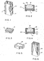
- a typical example is shown in Fig 1, wherein is the complete layered battery, 10 is one of the dry cell units and 17 is a casing in which the dry cell units 10 are packed.
- a conventional dry cell unit 10 is composed of a rectangular, composite positive electrode 15 containing manangese dioxide, a paper casing 14 which covers the bottom surface and the side surfaces of the composite positive electrode 15 (as also shown in Fig 3), a paper sheet 13 to abut the bottom surface of paprer casing 14, a negative electrode 12 consisting of a zinc sheet to abut paper sheet 13, and a carbon film 11 to abut negative electrode 12 so that composite positive electrode 15, paper casing 14, paper sheet 13, negative electrode (zinc sheet) 12 and carbon film 11 constitute a laminate which is further enclosed with a heat-shrinkable plastics shielding material or case 16 that. leaves the central area of the top surface of composite positive electrode 15 and the central area of the lower surface of carbon film 11 exposed.
- paper casing 14 which covers the bottom surface and sides of composite positive electrode 15, tends to expand after being soaked with electrolyte. Therefore, a large space at the bottom and around the composite positive electrode is occupied by the paper casing. As a result, a large portion of the space within the casing of a completed layered battery is not effectively utilized.
- this invention provides an improved layered dry-cell battery having a plurality of dry-cell units stacked one on top of another to form a series connection; said dry-cell units each comprising:
- This invention provides a layered dry-cell battery having a plurality of dry cell units 20 as shown in Figs 4 and 6.
- the dry cell units 20 are to be stacked one over another and packed in a casing in a similar manner to a conventional layered battery shown in Fig 1.
- the dry cell unit 20 comprises a composite positive electrode 25 which is composed of a mixture of manganese dioxide, ammoniumchloride, acetylene black, graphite powder and an electrolyte containing an aqueous acid solution as a binder, the mixture being compressed and formed into a tablet shape; lining 24, which is made of water-proof and acid-resisting material such as heat-shrinkable plastics, adapted to enclose the side or sides of tablet-shaped composite positive electrode 25 so as to leave the central area of the top and bottom surfaces exposed; a paper sheet 23 soaked with an aqueous acid solution to abut the exposed bottom surface of tablet-shaped composite positive electrode 25; a negative electrode 22 consisting of a zinc sheet to abut paper sheet 23; a carbon film 21 to abut negative electrode 22 so as to form a laminated construction, the laminate being provided with a heat shrinkable plastics shielding material or case 26 around the side or sides thereof as shown in Fig 4.
- a composite positive electrode 25 which is composed of
- Lining 24 is so disposed as to surround the side or sides of the tablet-shaped composite positive electrode 25 and then heated to shrink, as shown in Fig 5, so as . to enclose all the sides and corners of the tablet shaped composite positive electrode 25 leaving the central area of its top and bottom surfaces exposed.
- Heat shrinkable plastics shielding material or case 26 is disposed in the same manner around the laminate of tablet-shaped composite positive electrode 25 having-lining 24 surrounding its sides, paper sheet 23, negative electrode 22 and carbon film 21, as shown in Fig 4, leaving the central area of the top surface of the composite positive electrode and the lower surface of the carbon film exposed.
- the central part of the top surface of tablet-shaped composite positive electrode 15 is slightly elevated, as shown in Fig 4.
- the elevated top surface assures a good contact engagement with the upper surface of composite positive electrode 25 of one cell unit and the lower surface of carbon film 21 of another cell unit when they are stacked one over the other and packed in casing 27 as shown in Fig 6..
- lining 24 is made of water-proof and acid-resistant material such as heat shrinkable plastics, which will not expand after contact with electrolyte containing an aqueous acid solution, no extra space in casing 27 will be occupied by lining 24. As a result, the space within casing 27 can be effectively utilized or allocated, to enlarge the size or volume of composite positive electrode on which size the capacity, or the ampere-hour rating, of a complete layered battery depends.
Landscapes
- Chemical & Material Sciences (AREA)
- Chemical Kinetics & Catalysis (AREA)
- Electrochemistry (AREA)
- General Chemical & Material Sciences (AREA)
- Engineering & Computer Science (AREA)
- Manufacturing & Machinery (AREA)
- Sealing Battery Cases Or Jackets (AREA)
- Primary Cells (AREA)
- Cell Separators (AREA)
- Secondary Cells (AREA)
Abstract
Description
- This invention relates to a layered dry-cell battery and more particularly to a battery having a plurality of dry cell units stacked one over another to form a series connection, each dry cell unit having a composite positive electrode formed into a tablet shape whose side or sides are enclosed with a water-proof and acid-resisting lining.
- Conventional layered dry-cell batteries are generally composed of a plurality of dry cell units stacked one over another and packed in a casing. A typical example is shown in Fig 1, wherein is the complete layered battery, 10 is one of the dry cell units and 17 is a casing in which the
dry cell units 10 are packed. - A conventional
dry cell unit 10, as shown in Fig 2, is composed of a rectangular, compositepositive electrode 15 containing manangese dioxide, apaper casing 14 which covers the bottom surface and the side surfaces of the composite positive electrode 15 (as also shown in Fig 3), apaper sheet 13 to abut the bottom surface ofpaprer casing 14, anegative electrode 12 consisting of a zinc sheet to abutpaper sheet 13, and a carbon film 11 to abutnegative electrode 12 so that compositepositive electrode 15,paper casing 14,paper sheet 13, negative electrode (zinc sheet) 12 and carbon film 11 constitute a laminate which is further enclosed with a heat-shrinkable plastics shielding material orcase 16 that. leaves the central area of the top surface of compositepositive electrode 15 and the central area of the lower surface of carbon film 11 exposed. When assembling compositepositive electrode 15,paper casing 14 andpaper sheet 13, a suitable quantity of electrolyte such as an aqueous acid solution in added so as to soakpaper casing 14 andpaper sheet 13 with the aqueous acid solution, and therefore a voltage is generated betweencomposite electrode 15 and zinc sheetnegative electrode 17. When a plurality of the cell units are stacked one over another, that is, connected in a series, a voltage is provided equivalent to the sum of the voltages generated by each individual cell unit. - In such a conventional cell unit as described above
paper casing 14, which covers the bottom surface and sides of compositepositive electrode 15, tends to expand after being soaked with electrolyte. Therefore, a large space at the bottom and around the composite positive electrode is occupied by the paper casing. As a result, a large portion of the space within the casing of a completed layered battery is not effectively utilized. - It is a primary object of this invention to provide an improved battery of which the capacity, or the ampere-hour rating, is increased over conventional layered dry-cell batteries.
- In view of aforesaid problem with conventional batteries, this invention provides an improved layered dry-cell battery having a plurality of dry-cell units stacked one on top of another to form a series connection; said dry-cell units each comprising:
- a positive electrode which includes an electrolyte formed into a shape having a top surface, a bottom surface and at least one side;
- a water-proof and acid resistant lining enclosing the side or sides of the positive electrode and leaving exposed central areas of the top and bottom surfaces of the.positive electrode;
- a paper sheet abutting the bottom surface of the positive electrode;
- a negative electrode in sheet form abutting the paper sheet;
- a carbon film having an upper surface abutting the negative electrode and a lower surface; and a plastics case retaining the positive electrode the lining, the paper sheet, the negative electrode and the carbon film as a laminate with the central area of the top surface of the positive electrode and the central area of the lower surface of the carbon film exposed.
-
- Fig 1 is a perspective view of a conventional layered dry-cell battery, partially in section to show its internal arrangement.
- Fig 2 is an enlarged cross-sectional view of a dry cell unit of a conventional battery.
- Fig 3 is a perspective view of a composite positive electrode being wrapped in a paper case according to a conventional construction.
- Fig 4 is an enlarged cross-sectional view of a dry cell unit employed in the battery of this invention.
- Fig 5 is a perspective view of a composite positive electrode being enclosed with a plastics sheet material or case partially in section to show its configuration.
- Fig 6 is a perspective view of a complete battery of this invention, partially in section.
- This invention provides a layered dry-cell battery having a plurality of
dry cell units 20 as shown in Figs 4 and 6. Thedry cell units 20 are to be stacked one over another and packed in a casing in a similar manner to a conventional layered battery shown in Fig 1. - As shown in Fig 4, the
dry cell unit 20 according to this invention comprises a compositepositive electrode 25 which is composed of a mixture of manganese dioxide, ammoniumchloride, acetylene black, graphite powder and an electrolyte containing an aqueous acid solution as a binder, the mixture being compressed and formed into a tablet shape;lining 24, which is made of water-proof and acid-resisting material such as heat-shrinkable plastics, adapted to enclose the side or sides of tablet-shaped compositepositive electrode 25 so as to leave the central area of the top and bottom surfaces exposed; apaper sheet 23 soaked with an aqueous acid solution to abut the exposed bottom surface of tablet-shaped compositepositive electrode 25; anegative electrode 22 consisting of a zinc sheet to abutpaper sheet 23; acarbon film 21 to abutnegative electrode 22 so as to form a laminated construction, the laminate being provided with a heat shrinkable plastics shielding material orcase 26 around the side or sides thereof as shown in Fig 4. -
Lining 24 is so disposed as to surround the side or sides of the tablet-shaped compositepositive electrode 25 and then heated to shrink, as shown in Fig 5, so as . to enclose all the sides and corners of the tablet shaped compositepositive electrode 25 leaving the central area of its top and bottom surfaces exposed. Heat shrinkable plastics shielding material orcase 26 is disposed in the same manner around the laminate of tablet-shaped compositepositive electrode 25 having-lining 24 surrounding its sides,paper sheet 23,negative electrode 22 andcarbon film 21, as shown in Fig 4, leaving the central area of the top surface of the composite positive electrode and the lower surface of the carbon film exposed. - The central part of the top surface of tablet-shaped composite
positive electrode 15 is slightly elevated, as shown in Fig 4. The elevated top surface assures a good contact engagement with the upper surface of compositepositive electrode 25 of one cell unit and the lower surface ofcarbon film 21 of another cell unit when they are stacked one over the other and packed incasing 27 as shown in Fig 6.. - Because
lining 24 is made of water-proof and acid-resistant material such as heat shrinkable plastics, which will not expand after contact with electrolyte containing an aqueous acid solution, no extra space incasing 27 will be occupied bylining 24. As a result, the space withincasing 27 can be effectively utilized or allocated, to enlarge the size or volume of composite positive electrode on which size the capacity, or the ampere-hour rating, of a complete layered battery depends.
Claims (3)
Priority Applications (3)
| Application Number | Priority Date | Filing Date | Title |
|---|---|---|---|
| AT82304884T ATE20695T1 (en) | 1982-09-16 | 1982-09-16 | FLAT DRY BATTERIES. |
| EP82304884A EP0103658B1 (en) | 1982-09-16 | 1982-09-16 | A layered dry-cell battery |
| DE8282304884T DE3271942D1 (en) | 1982-09-16 | 1982-09-16 | A layered dry-cell battery |
Applications Claiming Priority (1)
| Application Number | Priority Date | Filing Date | Title |
|---|---|---|---|
| EP82304884A EP0103658B1 (en) | 1982-09-16 | 1982-09-16 | A layered dry-cell battery |
Publications (2)
| Publication Number | Publication Date |
|---|---|
| EP0103658A1 true EP0103658A1 (en) | 1984-03-28 |
| EP0103658B1 EP0103658B1 (en) | 1986-07-09 |
Family
ID=8189771
Family Applications (1)
| Application Number | Title | Priority Date | Filing Date |
|---|---|---|---|
| EP82304884A Expired EP0103658B1 (en) | 1982-09-16 | 1982-09-16 | A layered dry-cell battery |
Country Status (3)
| Country | Link |
|---|---|
| EP (1) | EP0103658B1 (en) |
| AT (1) | ATE20695T1 (en) |
| DE (1) | DE3271942D1 (en) |
Citations (5)
| Publication number | Priority date | Publication date | Assignee | Title |
|---|---|---|---|---|
| US2536697A (en) * | 1946-04-09 | 1951-01-02 | Ruben Samuel | Primary cell and battery |
| US2658936A (en) * | 1949-01-19 | 1953-11-10 | Gen Dry Batteries Inc | Dry cell battery |
| GB774151A (en) * | 1954-02-12 | 1957-05-08 | Wonder Piles | An electric battery with flat cells |
| FR1400194A (en) * | 1963-07-05 | 1965-05-21 | Electric Storage Battery Co | electric accumulator electrode |
| US4118860A (en) * | 1977-01-27 | 1978-10-10 | Polaroid Corporation | Method of making a flat battery |
-
1982
- 1982-09-16 DE DE8282304884T patent/DE3271942D1/en not_active Expired
- 1982-09-16 EP EP82304884A patent/EP0103658B1/en not_active Expired
- 1982-09-16 AT AT82304884T patent/ATE20695T1/en active
Patent Citations (5)
| Publication number | Priority date | Publication date | Assignee | Title |
|---|---|---|---|---|
| US2536697A (en) * | 1946-04-09 | 1951-01-02 | Ruben Samuel | Primary cell and battery |
| US2658936A (en) * | 1949-01-19 | 1953-11-10 | Gen Dry Batteries Inc | Dry cell battery |
| GB774151A (en) * | 1954-02-12 | 1957-05-08 | Wonder Piles | An electric battery with flat cells |
| FR1400194A (en) * | 1963-07-05 | 1965-05-21 | Electric Storage Battery Co | electric accumulator electrode |
| US4118860A (en) * | 1977-01-27 | 1978-10-10 | Polaroid Corporation | Method of making a flat battery |
Non-Patent Citations (1)
| Title |
|---|
| PATENTS ABSTRACTS OF JAPAN, vol. 5, no. 30 (E-47)(702), February 24, 1981, & JP - A - 55 157864 (FUJI DENKI KAGAKU K.K.) 08.12.1980 * |
Also Published As
| Publication number | Publication date |
|---|---|
| DE3271942D1 (en) | 1986-08-14 |
| EP0103658B1 (en) | 1986-07-09 |
| ATE20695T1 (en) | 1986-07-15 |
Similar Documents
| Publication | Publication Date | Title |
|---|---|---|
| EP1217681A3 (en) | Sealed lead-acid cells and batteries | |
| GB1332944A (en) | Electrochemical cell with spirally wound electrodes | |
| DE3685822D1 (en) | BATTERY. | |
| US2880259A (en) | Primary battery | |
| US3708340A (en) | Galvanic battery wherein each cell is enclosed in a cover comprising electrically insulating and electrically conductive plastic foils | |
| GB1529920A (en) | Electric batteries | |
| GB1422782A (en) | Alkaline electric cells | |
| GB1527460A (en) | Primary or secondary electric cell or battery particularly an alkaline storage cell or battery | |
| EP1264357B1 (en) | Battery comprising a plurality of series-connected galvanic cells | |
| GB1396340A (en) | Lead storage batte'y | |
| EP0103658B1 (en) | A layered dry-cell battery | |
| US3078329A (en) | Battery assembly | |
| US3247023A (en) | Lead-acid storage battery plate | |
| US2658936A (en) | Dry cell battery | |
| US3003011A (en) | System for the construction of electrical secondary cells, i.e. storage batteries | |
| GB2133922A (en) | Battery | |
| EP0195567A3 (en) | Bipolar storage battery | |
| ES8103483A1 (en) | Lead acid electric storage batteries. | |
| JPS639104Y2 (en) | ||
| JPS5956350A (en) | Laminated battery | |
| EP0406466A1 (en) | Storage battery | |
| GB2133921A (en) | Improvements relating to layer- built batteries | |
| US1867423A (en) | Shield for batteries and their parts | |
| GB2136193A (en) | Closed cylindrical storage battery | |
| KR900004585Y1 (en) | Electrode assembly |
Legal Events
| Date | Code | Title | Description |
|---|---|---|---|
| PUAI | Public reference made under article 153(3) epc to a published international application that has entered the european phase |
Free format text: ORIGINAL CODE: 0009012 |
|
| 17P | Request for examination filed |
Effective date: 19830916 |
|
| AK | Designated contracting states |
Designated state(s): AT BE CH DE FR GB IT LI LU NL SE |
|
| GRAA | (expected) grant |
Free format text: ORIGINAL CODE: 0009210 |
|
| AK | Designated contracting states |
Kind code of ref document: B1 Designated state(s): AT BE CH DE FR GB IT LI LU NL SE |
|
| PG25 | Lapsed in a contracting state [announced via postgrant information from national office to epo] |
Ref country code: NL Effective date: 19860709 Ref country code: LI Effective date: 19860709 Ref country code: CH Effective date: 19860709 Ref country code: AT Effective date: 19860709 |
|
| REF | Corresponds to: |
Ref document number: 20695 Country of ref document: AT Date of ref document: 19860715 Kind code of ref document: T |
|
| PG25 | Lapsed in a contracting state [announced via postgrant information from national office to epo] |
Ref country code: SE Effective date: 19860731 |
|
| REF | Corresponds to: |
Ref document number: 3271942 Country of ref document: DE Date of ref document: 19860814 |
|
| ITF | It: translation for a ep patent filed | ||
| PG25 | Lapsed in a contracting state [announced via postgrant information from national office to epo] |
Ref country code: LU Free format text: LAPSE BECAUSE OF NON-PAYMENT OF DUE FEES Effective date: 19860930 |
|
| REG | Reference to a national code |
Ref country code: CH Ref legal event code: PL |
|
| ET | Fr: translation filed | ||
| NLV1 | Nl: lapsed or annulled due to failure to fulfill the requirements of art. 29p and 29m of the patents act | ||
| PLBE | No opposition filed within time limit |
Free format text: ORIGINAL CODE: 0009261 |
|
| STAA | Information on the status of an ep patent application or granted ep patent |
Free format text: STATUS: NO OPPOSITION FILED WITHIN TIME LIMIT |
|
| 26N | No opposition filed | ||
| ITTA | It: last paid annual fee | ||
| PGFP | Annual fee paid to national office [announced via postgrant information from national office to epo] |
Ref country code: GB Payment date: 20011010 Year of fee payment: 20 Ref country code: FR Payment date: 20011010 Year of fee payment: 20 |
|
| PGFP | Annual fee paid to national office [announced via postgrant information from national office to epo] |
Ref country code: DE Payment date: 20011015 Year of fee payment: 20 |
|
| PGFP | Annual fee paid to national office [announced via postgrant information from national office to epo] |
Ref country code: BE Payment date: 20011116 Year of fee payment: 20 |
|
| REG | Reference to a national code |
Ref country code: GB Ref legal event code: IF02 |
|
| PG25 | Lapsed in a contracting state [announced via postgrant information from national office to epo] |
Ref country code: GB Free format text: LAPSE BECAUSE OF EXPIRATION OF PROTECTION Effective date: 20020915 |
|
| BE20 | Be: patent expired |
Owner name: *KAN-CHEUNG LO Effective date: 20020916 |
|
| REG | Reference to a national code |
Ref country code: GB Ref legal event code: PE20 Effective date: 20020915 |