EP0103526A2 - Gas convection oven - Google Patents
Gas convection oven Download PDFInfo
- Publication number
- EP0103526A2 EP0103526A2 EP83401784A EP83401784A EP0103526A2 EP 0103526 A2 EP0103526 A2 EP 0103526A2 EP 83401784 A EP83401784 A EP 83401784A EP 83401784 A EP83401784 A EP 83401784A EP 0103526 A2 EP0103526 A2 EP 0103526A2
- Authority
- EP
- European Patent Office
- Prior art keywords
- heat exchanger
- oven
- convection
- gas
- burner
- Prior art date
- Legal status (The legal status is an assumption and is not a legal conclusion. Google has not performed a legal analysis and makes no representation as to the accuracy of the status listed.)
- Granted
Links
Images


Classifications
-
- F—MECHANICAL ENGINEERING; LIGHTING; HEATING; WEAPONS; BLASTING
- F28—HEAT EXCHANGE IN GENERAL
- F28F—DETAILS OF HEAT-EXCHANGE AND HEAT-TRANSFER APPARATUS, OF GENERAL APPLICATION
- F28F1/00—Tubular elements; Assemblies of tubular elements
- F28F1/02—Tubular elements of cross-section which is non-circular
-
- F—MECHANICAL ENGINEERING; LIGHTING; HEATING; WEAPONS; BLASTING
- F24—HEATING; RANGES; VENTILATING
- F24C—DOMESTIC STOVES OR RANGES ; DETAILS OF DOMESTIC STOVES OR RANGES, OF GENERAL APPLICATION
- F24C15/00—Details
- F24C15/32—Arrangements of ducts for hot gases, e.g. in or around baking ovens
- F24C15/322—Arrangements of ducts for hot gases, e.g. in or around baking ovens with forced circulation
Definitions
- the present invention relates generally to heating and more particularly to gas convection ovens, especially those used for heating food, for example for thawing or cooking purposes.
- gas convection ovens useful in commercial applications, such as in restaurants, cafeterias, and the like, as opposed to domestic use.
- Food placed inside a convection oven is processed by moving heated air along a circulatory path directed and arranged to provide throughout the food chamber or heating chamber substantially uniform temperatures of a preselected and controllable level.
- the circulatory path is generally defined by the walls of the oven, by baffling and by the food supporting means in the food chamber.
- the air is moved along the circulatory path by a fan or blower usually located adjacent the food chamber in a convection blower chamber. The blower is in the circulatory path.
- the circulated air and gases in convection ovens has been heated by passing them over and around electrically heated coils, steam pipes; heated flues, or tube-like heat exchangers, such as that shown in the noted patent, and relying only upon an exchange of heat between the heating system and the air the desired air temperature in the oven could be maintained.
- the noted patent too, is disclosed the possibility of allowing the products of combustion actually to enter the circulatory air path of the convection oven but this occurs at a limited outlet area of the convection blower air flow.
- the burner is of the type that directs a jet of gas into the heat exchanger tube.
- the inlet to the heat exchanger tube also is open to the atmosphere so that air may be drawn into the heat exchanger tube to support combustion of the gas.
- the amount of air entering the heat exchanger tube thus, is uncontrolled, and there is the possibility of unwanted material entering the open inlet of the heat exchanger tube.
- the heat exchanger tube disclosed in such patent has several linear lengths connected together at angles to extend generally parallel to several of the walls of the convection blower chamber so that air blown by the convection blower would flow across at least several of those linear tubular extents to be heated by the hot gases flowing through the latter.
- a conical inlet baffle guides air from the heating or food chamber toward the center or inlet of the convection blower wheel, and a perimeter portion of such baffle and the oven walls guide air flow from the outlet of the convection blower wheel, as such air flows past the heat exchanger, into the heating compartment. Baffles on walls of the heating compartment and the oven walls further guide air flow toward the food or the material therein.
- one aspect of the present invention relates to a convection oven including a heating compartment, a package gas burner, a heat exchanger for conducting therethrough the products of combustion from combustion of gas initiated at the package gas burner, and a convection blower for blowing air past the heat exchanger for heating thereby and into the heating compartment for heating the same, and the blower including an inlet for drawing in air from the heating compartment for recirculation thereof past the heat exchanger and into the heating compartment.
- a convection oven includes a heating compartment, a burner for effecting combustion of gas, a heat exchanger for conducting therethrough the products of combustion from the combustion of gas initiated at the burner, and a convection blower for blowing air past the heat exchanger for heating thereby and into the heating compartment for heating the same, and the heat exchanger including a first tubular portion relatively proximate the burner and having a surface area configuration of a shape and position with respect to air flowing from the blower to draw air blown thereacross so as to flow across substantially the entire extent of such surface area.
- a heating system including a heat exchanger and a heat input source for supplying hot fluid- like material into the heat exchanger for flowing therein, and the heat exchanger has a surface area portion tending to draw fluid flowing over the exterior extent thereof towards such exterior so as to flow over substantially the entire extent of such surface area portion.
- a gas convection oven includes a blower compartment having plural walls, the adjacent walls being generally at right angle relation to each other, a heat exchanger for conducting products of gas combustion therethrough, a convection blower for blowing air across the heat exchanger and into a heating area for heating the latter, and a burner for burning gas at an inlet to the heat exchanger, the burner being a powered burner for delivering a forced combination flow of gas and air into the heat exchanger as combustion occurs, and the powered burner and convection blower being cooperatively related to provide substantially complete combustion of the gas.
- Another object is to improve the combustion efficiency in a gas comvection oven.
- An additional object is to improve the heat transfer efficiency in a gas convection oven.
- a further object is to improve the longevity and/or reliability of gas convection oven equipment.
- Still another object is to facilitate maintaining a gas convection oven.
- Still an additional object is to facilitate maintaining cleanliness of a gas convection oven.
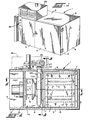
- a gas convection oven in accordance with the present invention is generally indicated at 1.
- the oven I is formed by a box-like housing 2 having well insulated top, bottom, side and end walls 3, 4, 5 and 6, respectively.
- the space within the housing 2 is divided into a relatively large heating/food processing compartment or chamber 7, which takes up a substantial part of the total interior space of the oven 1, a convection blower/heat exchanger chamber 8, and an equipment chamber 9, as is seen most clearly in Figs. 2 and 4.
- a wall 10 divides the equipment chamber from the convection blower/heat exchanger compartment 8, and there is a partial separation of the latter and the heating compartment 7 provided by an air inlet baffle 11.
- the wall 10 preferably is insulated to protect the motor and/or other equipment and controls contained in the equipment chamber 9 from the high temperatures normally present in the other two chambers.
- Food to be processed is conveniently placed in the heating chamber 7 through the oven door 12 and onto suitable means, such as trays, racks, etc., that may be removably supported in the heating compartment, for example in the manner shown in the above mentioned patent.
- suitable means such as trays, racks, etc.
- the trays are spaced apart throughout the heating chamber 7 to permit heated air and gases to be freely and uniformly circulated over, around, and about all the goods being processed. It is desirable to provide and to maintain all of the food at a relatively uniform temperature, and proper arrangement of the trays or similar means contributes to this result.
- openings 13 in the side wall baffles 14, 15 positioned in the heating chamber 7 to direct air flow from the convection blower compartment 8 into the heating chamber helps control air/tempera- ture distribution in the heating chamber 7, as is described in the above mentioned patent.
- the flow of heated air and gases to process the food is provided by a convection blower 18 having a conventional blower wheel 19 driven by an electric motor 20.
- the motor 20 is mounted on the wall 10 in the equipment chamber 9. The motor extends through the wall 10 and supports the wheel 19 centrally of one end of the food processing/heating chamber 7.
- the flow of air provided by the blower is directed in a circulatory path that traverses both the heating chamber 7 and the convection blower/heat exchange chamber 8, importantly, over and around the food to be processed. More particularly, air leaving the wheel 19 generally in a radial flow direction is directed along the front and back sides of the heating chamber 7 and toward the opposite end of the latter relative to the convection blower wheel via side passages provided by the side walls 13 and baffle plates 14, 15. Such circulation is indicated by the several arrows shown in Fig. 4, for example.
- the baffle plates 14, 15 are spaced from and parallel to the adjacent walls and are preferably supported on posts 22 or other means.
- the baffle plate 14 is supported on the back wall of the heating chamber 7 and the baffle plate 15 is supported on the door 16 which forms substantially the front wall l3 of the heating chamber 7.
- the baffle plates 14, 15 are spaced from each other and, accordingly, accommodate in the space therebetween a rack for supporting food to be processed in the heating chamber 7.
- the baffle plates 14, 15 terminate short of the end wall 6 so that circulation is continued from the side passages they provide into the central portion of the heating chamber 7 between the baffle plates, as the arrows show in Fig. 4. Openings preferably are provided in the baffle plates 14, 15 to permit secondary air circulation from the side passages into the central portion of the heating chamber to ensure temperature uniformity throughout the space containing the food.
- the air circulation path is directed back to the blower 19 by the conical inlet baffle 11 placed between the heating chamber 7 and blower chamber 8 between the side baffle plates 14, 15.
- the conical central portion 24 of the baffle 11 directs air circulation into the axial air inlet of the blower wheel 19, completing the air circulatory flow path.
- the baffle plates 14, 15 may have a series of varying diameter openings therein for directing flow directly onto food product in the heating chamber 7 in a uniform manner.
- slots or other types of openings may be provided in the baffle plates for such purpose.
- Heat is preferably provided for the gas convection oven 1 by a package gas burner 25, such as a Model G-2' SD power gas burner manufactured by the R. W. Beckett Corporation, Elyria, Ohio.
- a package gas burner 25 such as a Model G-2' SD power gas burner manufactured by the R. W. Beckett Corporation, Elyria, Ohio.
- power gas burner is provided as an integral package that can be mounted externally of the chambers 7, 8 but still be safely housed within a separate compartment 26, for example at the top of the oven 1.
- the power gas burner includes a pre-mix system that mixes gas and air, pressure controls, a power fan, various electronic controls, electric combustion ignition, and other safety, control and efficiency features.
- the same may be mounted in relatively minimum space that is highly accessible at the top front of the oven 1.
- the outlet 27 from the burner 25 may be coupled directly to the heat exchanger 28 of the present invention via a flange connection 29 that provides a flow path isolated from the external environment and, therefore, avoids the possibility of unnecessary additional air or other foreign material being drawn into the heat exchanger and into the internal portion of the oven 1.
- the power gas burner moreover, may be periodically ignited and shut down, for example under control of a conventional thermostat control including a heat sensor located in or proximate to the chambers 7, 8.
- the heat exchanger 28 which is seen most clearly in Figs. 2-7, the same is in the form of a tube 40 through which the hot flame and gas products of combustion derived from such flame produced by the gas/air mixture emanating from the power gas burner 25 may flow.
- Such flame and gas products of combustion effect heating of the heat exchanger tube. 40, which is positioned in the path of air flow from the convection blower 18 into the heating chamber 7 thereby to heat such flowing air.
- the inlet end 41 of the heat exchanger tube 40 is coupled at the flange connection 29 to the power gas burner 25, as was mentioned above.
- the heat exchanger tube 40 is of a generally spiral shape having respective linear portions joined at angular corners with the respective linear portions being positioned parallel and relatively adjacent front and back side walls, bottom wall, and a portion of the top wall of the convection blower chamber 8.
- the general shape and operation of the heat exchanger tube 40 is similar to what is described in the above mentioned patent.
- the heat exchanger tube 40 preferably is formed of stainless steel or other high temperature withstanding material. Such material also should have a good thermal conductivity in order to transfer heat from the material flowing therethrough to the air flowing over the external surface area thereof.
- the heat exchanger tube has a gas outlet tubular end 45 having a pair of slot-like cut-outs 46 directly facing into the air inlet area of the convection blower wheel 19.
- Such tubular outlet extension 45 passes through a cut-out 47 that accommodates the same in the inlet baffle 11. Air flowing around the side of the heat exchanger outlet 45 and being drawn into the convection blower wheel 19 central area tends to draw the gas products of combustion out from the heat exchanger tube and rapidly to disperse the same in the large quantity of air being circulated generally turbulently in the convection blower wheel 19 and area proximate thereto at the outlet thereof.
- burner-oven efficiency is in excess of 90%.
- the balance achieved in accordance with the present invention effects a high energy usage efficiency in connection with such combustion.
- heat is exchanged not only by air passing over the heat exchanger tube 40 but also by the subsequent dispersion of the remaining hot gas products of combustion into the circulating air, energy usage efficiency is appreciable and heat distribution in the oven is uniform. Too, since the combustion process is so thorough, it has been found that the amount of carbon monoxide entering the oven via the heat exchanger tube is very small, thus improving safe operation of the gas convection oven 1 and quality of food preparation therein.
- the heat exchanger tube 40 more particularly, includes generally linear portions 50, 51, 52, 53 and the outlet extension 45. Conventional mitred 45° angle elbow joints 54, 55, 56 join respective adjacent linear portions of the heat exchanger tube, as is seen in the several figures.
- the heat exchanger tube 40 is relatively securely mounted in the convection blower chamber 8 by various mounting brackets, such as those shown at 60, 61, and the slotted opening in the air inlet baffle 11 further secures the heat exchanger tube 40, particularly the outlet 45 thereof in position.
- the slot-like openings 46 in the outlet of tht is particularly securely mounted in the convection blower chamber 8 by various mounting brackets, such as those shown at 60, 61, and the slotted opening in the air inlet baffle 11 further secures the heat exchanger tube 40, particularly the outlet 45 thereof in position.
- the slot-like openings 46 in the outlet of tht is particularly securely mounted in the convection blower chamber 8 by various mounting brackets, such as those shown at 60, 61, and the slotted opening
- heat exchanger tube 40 help assure both structural strength of the outlet area where there is a relatively high velocity flow of air directed in a concentrated flow pattern on the curved upstream surface of the outlet 45 on the opposite side of such slot-like openings; and such surface curvature and slot-like openings cooperate to provide an air foil type effect to draw out from the heat exchanger tube 40 gas products of combustion at a flow rate that is proportionately representative of the rate of flow of air produced by the convection blower 19. Therefore, as the blower speed increases or decreases, the negative pressure or drawing out effect relative to the gas products of combustion from the heat exchanger tube 40 will vary in a corresponding fashion.
- adjacent the inlet portion of the heat exchanger tube 40 is a linear extent of the heat exchanger tube that is not of circular cross section, although the other portions illustrated in the drawings are generally of circular cross section, as can be seen, for example, in Fig. 4.
- the portion 65 is of elliptical cross section with the axis of the ellipse preferably oriented at a 45° angle with respect to the plane of the adjacent wall 66 of the convection blower chamber 8.
- Neck up and neck down pipe sections 67, 68 couple the elliptical cross section portion 65 of the heat exchanger tube 40 to the respective upstream and downstream portions of the heat exchanger tube 40.
- the elliptical cross section portion 65 it is the purpose of the elliptical cross section portion 65 to provide an external surface area in exposure to the air flowing from the convection blower wheel 19 tending to draw the air flow over substantially the entire extent of such heat exchanger tube portion 65 to maximize the cooling effect of such portion and to obtain maximum thermal energy transfer directly to the air. It has been found that the power gas burner 25 produces so much heat at the area of such portion 65 that the same tends to glow red evidencing substantial heat concentration. Were the portion 65 simply of typical circular cross section of the remaining extent of the heat exchanger tube 40 beyond the portion 65, the downstream back side of such heat exchanger tube would not receive maximum air flow thereon, and in fact would be somewhat shielded from air flow thereon, whereby such back side portion would tend to succumb to heat fatigue prematurely.
- the elliptical cross section portion or other shape that provides a configuration of the external surface area of the portion 65 such that the same would tend to draw maximum air flow thereover would avoid such premature heat fatigue.
- the above mentioned preferred 45° angle of the elliptical axis orientation, the larger radial portion of the ellipse being upstream and the narrower radial portion downstream relative to convection air flow direction, and the positioning of the portion 65 in proximity relation to the convection chamber wall and to an adjacent wall portion of the air inlet baffle 11 further assures guidance of the air flow against the entire surface area of the heat exchanger tube portion 65.
- Efficient combustion in the heat exchanger tube 40 generally concentrated in the portion 65, releases high amounts of heat, and the same is further promoted by reducing the resistance to gaseous fluid flow through the heat exchanger tube 40.
- the negative pressure effect at the outlet 46 enhances such effect even though the total length of the heat exchanger is relatively extensive.
- the extensive length helps to assure maximum exposure and thermal energy transfer to the air flowing across the heat exchanger and uniformity of distribution of thermal energy during operation of the gas convection oven.
- the locating of the convection blower wheel 19 centrally in the convection blower chamber 8 and relative to the spiral formation, as seen in Fig. 3, of the heat exchanger tube 40 further helps to balance the system with respect to heat distribution and to optimize thermal energy transfer efficiency.
- the flow restriction between the elliptical portion 65 and adjacent walls and the wider open areas at other parts of the heat exchanger tube also help balance heat distribution in the heating chamber 7.
- the length of the linear extent of the heat exchanger tube directly from the power gas burner 25 preferably is adequate to sheathe the entire flame from the burner 25. This avoids extensive heat concentration at the area where the first bend in the heat exchanger tube 40 occurs.
- Heat is introduced into the gas convection oven 1 by the exchange of heat from the heat cxchanger tube 40 to the air flowing thereover and directing of that air flow to the heating chamber 7 as well as from the gas products of combustion that enter via the outlet 45 of the heat exchanger tube 40.
- An outlet stack or flue 70 allows hot air or other gases to exit the gas convection oven 1 in a controlled manner.
- the stack 70 may be located in position to pass up through the burner housing portion or compartment 26, as is seen, for example, in Fig. 1, and may be coupled to a conventional vent pipe.
- the power gas burner 25 is positioned at the front top of the oven for access convenience for servicing and to provide maximum unimpeded oven food or other material capacity.
- the gas convection oven disclosed and claimed herein is well adapted to processing food, including thawing frozen foods and in addition to being used in the food service industry, may be used for other purposes as well.
- the side baffle plates 14, 15 and the conical inlet baffle 11 are removably mounted for ease and convenience in cleaning the heating chamber 7 and convection blower chamber 8.
- an air filter such as a metal filter, provided at the upstream end of the conical air inlet baffle 11 (means for mounting the sam'e being illustrated, for example, at 75 in Fig. 6) to remove particulate material from the circulating air.
- conventional means may be employed to provide moisture inlet to the heating chamber or convection blower chamber to maintain a desired humidity effect therein, as is well known in the art.
- moisture inlet to the heating chamber or convection blower chamber Preferably there is no need to provide supplemental air inlet passages for the gas convection oven.
- air in the heating chamber 7 and convection blower chamber 8 is continuously recirculated with there being a flow through of gaseous products from the heat exchanger tube into the chambers 7, 8 and, as appropriate, an outflow of gaseous material via the stack.
- FIG. 8 there is shown a modified convection blower chamber 8'.
- Such convection blower chamber is provided as part of a larger capacity gas convection oven I'.
- the several portions of the oven I' illustrated in Fig. 8 are designated with primed reference numerals where such parts correspond to those described above with reference to Figs. 1-7.
- the height of the gas convection oven l' is about twice that of the gas convection oven 1 and, accordingly, to provide for adequate air flow two blower wheels 19' are provided.
- One or more air inlet baffles ll one being designated by the phantom line 19' in Fig.
- the heat exchanger tube 40' extends along the lengths of the front, bottom and back walls of the convection blower chamber 8' and across a portion of the top wall with an outlet 45' of the type shown in Fig. 3 opening toward the inlet to the upper blower wheel 19'.
- the elliptical cross section portion 65' of the heat exchanger tube 40' is of approximately the same length as that disclosed at 65 in Fig. 3 but may be extended, if necessary, to accommodate a larger flame and greater heat intensity produced by the power gas burner or package burner 25'. Operation of the gas convection oven I' would be similar to that of the gas convection oven 1 except that both convection blower wheels 19' ordinary would be employed to effect the desired air circulation in the heating chamber (not shown).
- gas provided the power gas burner 25, for example, and air mixed with such gas is ignited and combustion occurs producing a flame that enters the heat exchanger tube portion 65.
- the convection blower wheel 19 is turned by the motor 20 causing air flow across the entire heat exchanger tube 40 to effect heat transfer to the air and cooling of the heat exchanger tube. Air flow follows the arrows depicting the air flow pattern, for example, in Fig. 4 tending to heat the heating chamber 7 and the food product or other material therein.
- Controls 80 of conventional design may be provided adjacent the equipment chamber 9 for effecting monitoring and control of the various portions of the convection oven 1.
- Such controls may include the above mentioned thermostat as well as speed controls for the convection blower 19.
- the invention does provide means for effecting heating of food or other material in a heating chamber 7 in a relatively highly efficient and energy efficient manner.
Abstract
Description
- The present invention relates generally to heating and more particularly to gas convection ovens, especially those used for heating food, for example for thawing or cooking purposes. In accordance with the preferred embodiment and best mode of the present invention there is disclosed a gas convection oven useful in commercial applications, such as in restaurants, cafeterias, and the like, as opposed to domestic use.
- In commercial applications for food heating it is necessary to provide relatively large heating compartments for containing food intended for cooking, baking, frying, thawing, etc. It is desirable that heat in such heating compartments be relatively uniformly distributed throughout the same for uniform or controlled heating of product therein. It is desirable, too, that the entire appliance, i.e. a gas convection oven, be capable of being cleaned with relative ease in order to maintain high standards of cleanliness. It also is important to maintain a high degree of reliability of the equipment and facility of servicing the same.
- In U.S. Patent No. 3,605,717 there is disclosed a convection oven in which combustion of gas effects the primary heat input. Disclosure of such patent is incorporated in its entirety by reference. In such patent there is disclosed principles of convection heating in a commercial heating appliance.
- Food placed inside a convection oven is processed by moving heated air along a circulatory path directed and arranged to provide throughout the food chamber or heating chamber substantially uniform temperatures of a preselected and controllable level. The circulatory path is generally defined by the walls of the oven, by baffling and by the food supporting means in the food chamber. The air is moved along the circulatory path by a fan or blower usually located adjacent the food chamber in a convection blower chamber. The blower is in the circulatory path.
- In the past, the circulated air and gases in convection ovens has been heated by passing them over and around electrically heated coils, steam pipes; heated flues, or tube-like heat exchangers, such as that shown in the noted patent, and relying only upon an exchange of heat between the heating system and the air the desired air temperature in the oven could be maintained. In the noted patent, too, is disclosed the possibility of allowing the products of combustion actually to enter the circulatory air path of the convection oven but this occurs at a limited outlet area of the convection blower air flow. In such patent the burner is of the type that directs a jet of gas into the heat exchanger tube. The inlet to the heat exchanger tube, however, also is open to the atmosphere so that air may be drawn into the heat exchanger tube to support combustion of the gas. The amount of air entering the heat exchanger tube, thus, is uncontrolled, and there is the possibility of unwanted material entering the open inlet of the heat exchanger tube.
- The heat exchanger tube disclosed in such patent has several linear lengths connected together at angles to extend generally parallel to several of the walls of the convection blower chamber so that air blown by the convection blower would flow across at least several of those linear tubular extents to be heated by the hot gases flowing through the latter. A conical inlet baffle guides air from the heating or food chamber toward the center or inlet of the convection blower wheel, and a perimeter portion of such baffle and the oven walls guide air flow from the outlet of the convection blower wheel, as such air flows past the heat exchanger, into the heating compartment. Baffles on walls of the heating compartment and the oven walls further guide air flow toward the food or the material therein.
- In the present day energy climate, it is desirable to try to optimize energy usage efficiency. In the context of gas convection heating, it is desirable to optimize the thoroughness of the heat exchange process and combustion efficiency. It also is desirable, at the same time, to improve reliability of the convection heating equipment, to facilitate servicing of such equipment, to maintain cleanliness of such equipment, and so on.
- With the foregoing and following description in mind, then, one aspect of the present invention relates to a convection oven including a heating compartment, a package gas burner, a heat exchanger for conducting therethrough the products of combustion from combustion of gas initiated at the package gas burner, and a convection blower for blowing air past the heat exchanger for heating thereby and into the heating compartment for heating the same, and the blower including an inlet for drawing in air from the heating compartment for recirculation thereof past the heat exchanger and into the heating compartment.
- Briefly, according to another aspect of the invention a convection oven includes a heating compartment, a burner for effecting combustion of gas, a heat exchanger for conducting therethrough the products of combustion from the combustion of gas initiated at the burner, and a convection blower for blowing air past the heat exchanger for heating thereby and into the heating compartment for heating the same, and the heat exchanger including a first tubular portion relatively proximate the burner and having a surface area configuration of a shape and position with respect to air flowing from the blower to draw air blown thereacross so as to flow across substantially the entire extent of such surface area.
- According to an additional aspect there is a heating system including a heat exchanger and a heat input source for supplying hot fluid- like material into the heat exchanger for flowing therein, and the heat exchanger has a surface area portion tending to draw fluid flowing over the exterior extent thereof towards such exterior so as to flow over substantially the entire extent of such surface area portion.
- According to a further aspect of the invention, a gas convection oven includes a blower compartment having plural walls, the adjacent walls being generally at right angle relation to each other, a heat exchanger for conducting products of gas combustion therethrough, a convection blower for blowing air across the heat exchanger and into a heating area for heating the latter, and a burner for burning gas at an inlet to the heat exchanger, the burner being a powered burner for delivering a forced combination flow of gas and air into the heat exchanger as combustion occurs, and the powered burner and convection blower being cooperatively related to provide substantially complete combustion of the gas.
- It is, therefore, a primary object of the present invention to provide improvements in gas convection heating system, particularly ovens, such as those employed in commercial food heating.
- Another object is to improve the combustion efficiency in a gas comvection oven.
- An additional object is to improve the heat transfer efficiency in a gas convection oven.
- A further object is to improve the longevity and/or reliability of gas convection oven equipment.
- Still another object is to facilitate maintaining a gas convection oven.
- Still an additional object is to facilitate maintaining cleanliness of a gas convection oven.
- Even another object is to improve the safe operation of a gas convection oven.
- These and other objects and advantages of the present invention will become more apparent as the following description proceeds.
- To the accomplishment of the foregoing and related ends, the invention, then, comprises the features hereinafter fully described in the specification and particularly pointed out in the claims, the following description and the annexed drawings setting forth in detail certain illustrative embodiments of the invention, these being indicative, however, of but several of the various ways in which the principles of the invention may be employed.
- In the annexed drawings:
- Fig. 1 is a perspective view of a gas convection oven embodying a preferred form of the present invention;
- Fig. 2 is a side elevation view of the oven of Fig. 1 and sectioned as indicated;
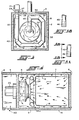
- Fig. 3 is a transverse section through the preferred embodiment taken in the planes indicated at 3-3 in Fig. 2;
- Fig. 4 is a top plan view sectioned on the planes of 4-4 in Fig. 2;
- Figs. 5A and 5B are, respectively, side and back views of the heat exchanger tube outlet;
- Fig. 6 is an enlarged perspective view of the convection blower/ heat exchanger chamber with the inlet baffle and air filter removed;
- Fig. 7 is an enlarged perspective view looking toward the convection blower/heat exchanger chamber with the conical air inlet baffle ready to be positioned in final assembly relation dividing such chamber from the heating chamber; and
- Fig. 8 is a schematic elevation view of the convection blower/ heat exchanger chamber of a modified gas convection oven having plural convection blowers.
- Referring now in detail to the drawings, wherein like reference numerals designate like parts in the several figures, and initially to Figs. 1-6, a gas convection oven in accordance with the present invention is generally indicated at 1. The oven I is formed by a box-
like housing 2 having well insulated top, bottom, side andend walls housing 2 is divided into a relatively large heating/food processing compartment orchamber 7, which takes up a substantial part of the total interior space of theoven 1, a convection blower/heat exchanger chamber 8, and anequipment chamber 9, as is seen most clearly in Figs. 2 and 4. Awall 10 divides the equipment chamber from the convection blower/heat exchanger compartment 8, and there is a partial separation of the latter and theheating compartment 7 provided by anair inlet baffle 11. Thewall 10 preferably is insulated to protect the motor and/or other equipment and controls contained in theequipment chamber 9 from the high temperatures normally present in the other two chambers. - Food to be processed is conveniently placed in the
heating chamber 7 through the oven door 12 and onto suitable means, such as trays, racks, etc., that may be removably supported in the heating compartment, for example in the manner shown in the above mentioned patent. Preferably the trays are spaced apart throughout theheating chamber 7 to permit heated air and gases to be freely and uniformly circulated over, around, and about all the goods being processed. It is desirable to provide and to maintain all of the food at a relatively uniform temperature, and proper arrangement of the trays or similar means contributes to this result. Furthermore, the arrangement ofopenings 13 in theside wall baffles heating chamber 7 to direct air flow from theconvection blower compartment 8 into the heating chamber helps control air/tempera- ture distribution in theheating chamber 7, as is described in the above mentioned patent. - The flow of heated air and gases to process the food is provided by a
convection blower 18 having aconventional blower wheel 19 driven by anelectric motor 20. Themotor 20 is mounted on thewall 10 in theequipment chamber 9. The motor extends through thewall 10 and supports thewheel 19 centrally of one end of the food processing/heating chamber 7. - The flow of air provided by the blower is directed in a circulatory path that traverses both the
heating chamber 7 and the convection blower/heat exchange chamber 8, importantly, over and around the food to be processed. More particularly, air leaving thewheel 19 generally in a radial flow direction is directed along the front and back sides of theheating chamber 7 and toward the opposite end of the latter relative to the convection blower wheel via side passages provided by theside walls 13 andbaffle plates baffle plates baffle plate 14 is supported on the back wall of theheating chamber 7 and thebaffle plate 15 is supported on thedoor 16 which forms substantially the front wall l3 of theheating chamber 7. Thebaffle plates heating chamber 7. - The
baffle plates end wall 6 so that circulation is continued from the side passages they provide into the central portion of theheating chamber 7 between the baffle plates, as the arrows show in Fig. 4. Openings preferably are provided in thebaffle plates - The air circulation path is directed back to the
blower 19 by theconical inlet baffle 11 placed between theheating chamber 7 andblower chamber 8 between theside baffle plates central portion 24 of thebaffle 11 directs air circulation into the axial air inlet of theblower wheel 19, completing the air circulatory flow path. - As is shown in Fig. 2, the
baffle plates heating chamber 7 in a uniform manner. Alternatively, slots or other types of openings may be provided in the baffle plates for such purpose. - Heat is preferably provided for the
gas convection oven 1 by apackage gas burner 25, such as a Model G-2' SD power gas burner manufactured by the R. W. Beckett Corporation, Elyria, Ohio. Such as power gas burner is provided as an integral package that can be mounted externally of thechambers separate compartment 26, for example at the top of theoven 1. The power gas burner includes a pre-mix system that mixes gas and air, pressure controls, a power fan, various electronic controls, electric combustion ignition, and other safety, control and efficiency features. - Using such a package gas burner, the same may be mounted in relatively minimum space that is highly accessible at the top front of the
oven 1. Moreover, theoutlet 27 from theburner 25 may be coupled directly to theheat exchanger 28 of the present invention via aflange connection 29 that provides a flow path isolated from the external environment and, therefore, avoids the possibility of unnecessary additional air or other foreign material being drawn into the heat exchanger and into the internal portion of theoven 1. The power gas burner, moreover, may be periodically ignited and shut down, for example under control of a conventional thermostat control including a heat sensor located in or proximate to thechambers - Using the power gas burner in accordance with the present invention energy efficiency is improved because there is no escape of heat at the area of the combustion flame. Safe operation is enhanced because of the shielding of the combustion flame, it being confined at the outlet of the power gas burner and in the heat exchanger tube, which will be described in greater detail below. Additionally, the possibility of foreign material entering the heat exchanger tube and subsequently itself burning or contaminating the material in the
heating chamber 7 is avoided using the power gas burner/heat exchanger arrangement of the present invention. - Referring now to the
heat exchanger 28, which is seen most clearly in Figs. 2-7, the same is in the form of atube 40 through which the hot flame and gas products of combustion derived from such flame produced by the gas/air mixture emanating from thepower gas burner 25 may flow. Such flame and gas products of combustion effect heating of the heat exchanger tube. 40, which is positioned in the path of air flow from theconvection blower 18 into theheating chamber 7 thereby to heat such flowing air. Theinlet end 41 of theheat exchanger tube 40 is coupled at theflange connection 29 to thepower gas burner 25, as was mentioned above. Theheat exchanger tube 40 is of a generally spiral shape having respective linear portions joined at angular corners with the respective linear portions being positioned parallel and relatively adjacent front and back side walls, bottom wall, and a portion of the top wall of theconvection blower chamber 8. The general shape and operation of theheat exchanger tube 40 is similar to what is described in the above mentioned patent. - Due to the high intensity and substantial heat produced by the gas combustion at the outlet of the
power gas burner 25 relative to the cooling effect achieved in the past using an open gun type burner for gas convection ovens, theheat exchanger tube 40 preferably is formed of stainless steel or other high temperature withstanding material. Such material also should have a good thermal conductivity in order to transfer heat from the material flowing therethrough to the air flowing over the external surface area thereof. - Preferably the heat exchanger tube has a gas outlet
tubular end 45 having a pair of slot-like cut-outs 46 directly facing into the air inlet area of theconvection blower wheel 19. Suchtubular outlet extension 45 passes through a cut-out 47 that accommodates the same in theinlet baffle 11. Air flowing around the side of theheat exchanger outlet 45 and being drawn into theconvection blower wheel 19 central area tends to draw the gas products of combustion out from the heat exchanger tube and rapidly to disperse the same in the large quantity of air being circulated generally turbulently in theconvection blower wheel 19 and area proximate thereto at the outlet thereof. It has been found that using thepower gas burner 25,heat exchanger tube 40 and particular outlet 45-46 arrangement of the present invention, burner-oven efficiency is in excess of 90%. Thus, the balance achieved in accordance with the present invention effects a high energy usage efficiency in connection with such combustion. Moreover, because heat is exchanged not only by air passing over theheat exchanger tube 40 but also by the subsequent dispersion of the remaining hot gas products of combustion into the circulating air, energy usage efficiency is appreciable and heat distribution in the oven is uniform. Too, since the combustion process is so thorough, it has been found that the amount of carbon monoxide entering the oven via the heat exchanger tube is very small, thus improving safe operation of thegas convection oven 1 and quality of food preparation therein. - The
heat exchanger tube 40, more particularly, includes generallylinear portions outlet extension 45. Conventional mitred 45° angle elbow joints 54, 55, 56 join respective adjacent linear portions of the heat exchanger tube, as is seen in the several figures. Theheat exchanger tube 40 is relatively securely mounted in theconvection blower chamber 8 by various mounting brackets, such as those shown at 60, 61, and the slotted opening in theair inlet baffle 11 further secures theheat exchanger tube 40, particularly theoutlet 45 thereof in position. The slot-like openings 46 in the outlet of tht.heat exchanger tube 40 help assure both structural strength of the outlet area where there is a relatively high velocity flow of air directed in a concentrated flow pattern on the curved upstream surface of theoutlet 45 on the opposite side of such slot-like openings; and such surface curvature and slot-like openings cooperate to provide an air foil type effect to draw out from theheat exchanger tube 40 gas products of combustion at a flow rate that is proportionately representative of the rate of flow of air produced by theconvection blower 19. Therefore, as the blower speed increases or decreases, the negative pressure or drawing out effect relative to the gas products of combustion from theheat exchanger tube 40 will vary in a corresponding fashion. - Referring, now, particularly to Figs. 3, 4 and 6, adjacent the inlet portion of the
heat exchanger tube 40 is a linear extent of the heat exchanger tube that is not of circular cross section, although the other portions illustrated in the drawings are generally of circular cross section, as can be seen, for example, in Fig. 4. However, theportion 65 is of elliptical cross section with the axis of the ellipse preferably oriented at a 45° angle with respect to the plane of the adjacent wall 66 of theconvection blower chamber 8. Neck up and neck downpipe sections 67, 68 couple the ellipticalcross section portion 65 of theheat exchanger tube 40 to the respective upstream and downstream portions of theheat exchanger tube 40. It is the purpose of the ellipticalcross section portion 65 to provide an external surface area in exposure to the air flowing from theconvection blower wheel 19 tending to draw the air flow over substantially the entire extent of such heatexchanger tube portion 65 to maximize the cooling effect of such portion and to obtain maximum thermal energy transfer directly to the air. It has been found that thepower gas burner 25 produces so much heat at the area ofsuch portion 65 that the same tends to glow red evidencing substantial heat concentration. Were theportion 65 simply of typical circular cross section of the remaining extent of theheat exchanger tube 40 beyond theportion 65, the downstream back side of such heat exchanger tube would not receive maximum air flow thereon, and in fact would be somewhat shielded from air flow thereon, whereby such back side portion would tend to succumb to heat fatigue prematurely. In contrast, the elliptical cross section portion or other shape that provides a configuration of the external surface area of theportion 65 such that the same would tend to draw maximum air flow thereover would avoid such premature heat fatigue. Further to assure such maximum air flow, the above mentioned preferred 45° angle of the elliptical axis orientation, the larger radial portion of the ellipse being upstream and the narrower radial portion downstream relative to convection air flow direction, and the positioning of theportion 65 in proximity relation to the convection chamber wall and to an adjacent wall portion of theair inlet baffle 11 further assures guidance of the air flow against the entire surface area of the heatexchanger tube portion 65. - Efficient combustion in the
heat exchanger tube 40, generally concentrated in theportion 65, releases high amounts of heat, and the same is further promoted by reducing the resistance to gaseous fluid flow through theheat exchanger tube 40. Thus, the negative pressure effect at theoutlet 46 enhances such effect even though the total length of the heat exchanger is relatively extensive. The extensive length, however, helps to assure maximum exposure and thermal energy transfer to the air flowing across the heat exchanger and uniformity of distribution of thermal energy during operation of the gas convection oven. The locating of theconvection blower wheel 19 centrally in theconvection blower chamber 8 and relative to the spiral formation, as seen in Fig. 3, of theheat exchanger tube 40 further helps to balance the system with respect to heat distribution and to optimize thermal energy transfer efficiency. The flow restriction between theelliptical portion 65 and adjacent walls and the wider open areas at other parts of the heat exchanger tube also help balance heat distribution in theheating chamber 7. - The length of the linear extent of the heat exchanger tube directly from the
power gas burner 25 preferably is adequate to sheathe the entire flame from theburner 25. This avoids extensive heat concentration at the area where the first bend in theheat exchanger tube 40 occurs. - Heat is introduced into the
gas convection oven 1 by the exchange of heat from theheat cxchanger tube 40 to the air flowing thereover and directing of that air flow to theheating chamber 7 as well as from the gas products of combustion that enter via theoutlet 45 of theheat exchanger tube 40. - An outlet stack or flue 70 allows hot air or other gases to exit the
gas convection oven 1 in a controlled manner. The stack 70 may be located in position to pass up through the burner housing portion orcompartment 26, as is seen, for example, in Fig. 1, and may be coupled to a conventional vent pipe. - Preferably the
power gas burner 25 is positioned at the front top of the oven for access convenience for servicing and to provide maximum unimpeded oven food or other material capacity. - The gas convection oven disclosed and claimed herein is well adapted to processing food, including thawing frozen foods and in addition to being used in the food service industry, may be used for other purposes as well. The
side baffle plates conical inlet baffle 11 are removably mounted for ease and convenience in cleaning theheating chamber 7 andconvection blower chamber 8. Moreover, preferably an air filter, such as a metal filter, provided at the upstream end of the conical air inlet baffle 11 (means for mounting the sam'e being illustrated, for example, at 75 in Fig. 6) to remove particulate material from the circulating air. Moreover, if desired, conventional means may be employed to provide moisture inlet to the heating chamber or convection blower chamber to maintain a desired humidity effect therein, as is well known in the art. Preferably there is no need to provide supplemental air inlet passages for the gas convection oven. Rather, air in theheating chamber 7 andconvection blower chamber 8 is continuously recirculated with there being a flow through of gaseous products from the heat exchanger tube into thechambers - Turning briefly to Fig. 8, there is shown a modified convection blower chamber 8'. Such convection blower chamber is provided as part of a larger capacity gas convection oven I'. The several portions of the oven I' illustrated in Fig. 8 are designated with primed reference numerals where such parts correspond to those described above with reference to Figs. 1-7. The height of the gas convection oven l' is about twice that of the
gas convection oven 1 and, accordingly, to provide for adequate air flow two blower wheels 19' are provided. One or more air inlet baffles ll, one being designated by the phantom line 19' in Fig. 8 directs air from the heating chamber (not shown) of the enlarged gas convection oven 1' into the convection blower chamber 8'. The heat exchanger tube 40' extends along the lengths of the front, bottom and back walls of the convection blower chamber 8' and across a portion of the top wall with an outlet 45' of the type shown in Fig. 3 opening toward the inlet to the upper blower wheel 19'. The elliptical cross section portion 65' of the heat exchanger tube 40' is of approximately the same length as that disclosed at 65 in Fig. 3 but may be extended, if necessary, to accommodate a larger flame and greater heat intensity produced by the power gas burner or package burner 25'. Operation of the gas convection oven I' would be similar to that of thegas convection oven 1 except that both convection blower wheels 19' ordinary would be employed to effect the desired air circulation in the heating chamber (not shown). - In use of the
gas convection ovens 1, 1', gas provided thepower gas burner 25, for example, and air mixed with such gas is ignited and combustion occurs producing a flame that enters the heatexchanger tube portion 65. Theconvection blower wheel 19 is turned by themotor 20 causing air flow across the entireheat exchanger tube 40 to effect heat transfer to the air and cooling of the heat exchanger tube. Air flow follows the arrows depicting the air flow pattern, for example, in Fig. 4 tending to heat theheating chamber 7 and the food product or other material therein. -
Controls 80 of conventional design may be provided adjacent theequipment chamber 9 for effecting monitoring and control of the various portions of theconvection oven 1. Such controls may include the above mentioned thermostat as well as speed controls for theconvection blower 19. - In view of the foregoing it will be appreciated that the invention does provide means for effecting heating of food or other material in a
heating chamber 7 in a relatively highly efficient and energy efficient manner.
Claims (18)
Priority Applications (1)
| Application Number | Priority Date | Filing Date | Title |
|---|---|---|---|
| AT83401784T ATE43704T1 (en) | 1982-09-14 | 1983-09-13 | GAS HEATED CONVECTION OVEN. |
Applications Claiming Priority (2)
| Application Number | Priority Date | Filing Date | Title |
|---|---|---|---|
| US418056 | 1982-09-14 | ||
| US06/418,056 US4484561A (en) | 1982-09-14 | 1982-09-14 | Gas convection oven |
Publications (3)
| Publication Number | Publication Date |
|---|---|
| EP0103526A2 true EP0103526A2 (en) | 1984-03-21 |
| EP0103526A3 EP0103526A3 (en) | 1986-02-05 |
| EP0103526B1 EP0103526B1 (en) | 1989-05-31 |
Family
ID=23656500
Family Applications (1)
| Application Number | Title | Priority Date | Filing Date |
|---|---|---|---|
| EP83401784A Expired EP0103526B1 (en) | 1982-09-14 | 1983-09-13 | Gas convection oven |
Country Status (6)
| Country | Link |
|---|---|
| US (1) | US4484561A (en) |
| EP (1) | EP0103526B1 (en) |
| JP (1) | JPS5971931A (en) |
| AT (1) | ATE43704T1 (en) |
| CA (1) | CA1211018A (en) |
| DE (1) | DE3379970D1 (en) |
Cited By (7)
| Publication number | Priority date | Publication date | Assignee | Title |
|---|---|---|---|---|
| EP0244927A2 (en) * | 1986-05-01 | 1987-11-11 | Premark Feg Corporation | Gas convection oven |
| GB2279224A (en) * | 1993-05-05 | 1995-01-04 | Haas Franz Waffelmasch | Continuous baker's oven |
| FR2710401A1 (en) * | 1993-09-22 | 1995-03-31 | Rosinox | Gas stove with hot-air agitation |
| GB2305237A (en) * | 1995-09-14 | 1997-04-02 | Electrolux Zanussi Grandi Impianti Spa | Forced convection oven |
| FR2899317A1 (en) * | 2006-04-03 | 2007-10-05 | Thirode Grandes Cuisines Poligny | Heat exchanger for gas burner of e.g. gas oven, has connecting rod fixed to large diameter tubular part and small diameter pipes, where tubular part, connecting rod and pipes form ring while leaving central space of ring to be free |
| WO2011116170A3 (en) * | 2010-03-17 | 2011-12-15 | Duke Manufacturing Co. | An oven for heating food |
| EP3460339A1 (en) * | 2017-09-22 | 2019-03-27 | Franke Technology and Trademark Ltd | Fan oven with additional shroud element |
Families Citing this family (30)
| Publication number | Priority date | Publication date | Assignee | Title |
|---|---|---|---|---|
| US4671250A (en) * | 1986-07-28 | 1987-06-09 | Thermo Electron Corporation | Direct-firing gas convection oven |
| US4854860A (en) * | 1987-12-02 | 1989-08-08 | Gas Research Institute | Convective heat transfer within an industrial heat treating furnace |
| US4813398A (en) * | 1988-05-09 | 1989-03-21 | Hobart Corporation | Convection oven |
| US4867132A (en) * | 1988-11-23 | 1989-09-19 | Garland Commercial Industries, Inc. | Gas fired convection oven with improved air delivery and heat exchange structure |
| US4972824A (en) * | 1988-12-02 | 1990-11-27 | Welbilt Corporation | Commercial hot air impingement cooking apparatus |
| US4928663A (en) * | 1989-01-31 | 1990-05-29 | Bakers Pride Oven Co. | Enhanced air-flow convection oven |
| US4966546A (en) * | 1989-05-01 | 1990-10-30 | Mobil Oil Corporation | Convective thermoforming oven |
| US5165889A (en) * | 1989-05-19 | 1992-11-24 | Import-Export Research And Development, Inc. | Gas convection oven with heat exchanger and baffles |
| US5016606A (en) * | 1989-08-31 | 1991-05-21 | Gas Research Institute | Gas-fired oven |
| US6140626A (en) * | 1998-04-23 | 2000-10-31 | Turbochef Technologies, Inc. | System for rapid air temperature modification in a recycling oven |
| US5845631A (en) * | 1997-08-21 | 1998-12-08 | Kerry Ingredients, Inc. | Heat exchanger for convection baking ovens |
| US6615819B1 (en) | 2000-03-10 | 2003-09-09 | General Electric Company | Convection oven |
| US6717114B2 (en) | 2001-12-14 | 2004-04-06 | Maytag Corporation | Convection fan assembly for a cooking appliance |
| US20050103322A1 (en) * | 2003-11-14 | 2005-05-19 | Smith Robert L. | Dual flow convection oven |
| PL1714084T3 (en) * | 2003-12-30 | 2013-07-31 | Arcelik As | An owen |
| DE102006004900A1 (en) * | 2006-02-03 | 2007-08-16 | Viessmann Werke Gmbh & Co Kg | heater |
| US8075304B2 (en) * | 2006-10-19 | 2011-12-13 | Wayne/Scott Fetzer Company | Modulated power burner system and method |
| US8022341B2 (en) * | 2007-05-15 | 2011-09-20 | Appliance Scientific, Inc. | High-speed cooking oven with optimized cooking efficiency |
| US8138452B2 (en) * | 2008-07-14 | 2012-03-20 | Whirlpool Corporation | Convection oven |
| DE102008053145A1 (en) * | 2008-10-24 | 2010-04-29 | Rational Ag | Flow guiding device for a cooking appliance |
| DE102008058718A1 (en) * | 2008-11-24 | 2010-05-27 | Rational Ag | Cooking device i.e. gas confection oven, has heat exchanger tube whose heat energy transfer coefficient per unit length increases for transferring heat energy from wall of tube to medium |
| JP2011147468A (en) * | 2010-01-19 | 2011-08-04 | Nepuree Corp | Device and method for heating hood material |
| US8895902B2 (en) | 2010-03-17 | 2014-11-25 | Duke Manufacturing Co. | Oven for heating food |
| US9127888B2 (en) * | 2010-07-02 | 2015-09-08 | Asc Process Systems | Industrial oven for curing composite material structures |
| US9372005B2 (en) * | 2012-11-30 | 2016-06-21 | Alto-Shaam, Inc. | Heat exchanger for oven |
| US9879865B2 (en) | 2015-06-08 | 2018-01-30 | Alto-Shaam, Inc. | Cooking oven |
| US10337745B2 (en) | 2015-06-08 | 2019-07-02 | Alto-Shaam, Inc. | Convection oven |
| US10890336B2 (en) | 2015-06-08 | 2021-01-12 | Alto-Shaam, Inc. | Thermal management system for multizone oven |
| US9677774B2 (en) | 2015-06-08 | 2017-06-13 | Alto-Shaam, Inc. | Multi-zone oven with variable cavity sizes |
| US10088172B2 (en) | 2016-07-29 | 2018-10-02 | Alto-Shaam, Inc. | Oven using structured air |
Citations (3)
| Publication number | Priority date | Publication date | Assignee | Title |
|---|---|---|---|---|
| US2410285A (en) * | 1941-04-18 | 1946-10-29 | John H Leonard | Gas range oven |
| US3384068A (en) * | 1966-12-09 | 1968-05-21 | American Gas Ass | Gas oven system |
| US3605717A (en) * | 1969-11-10 | 1971-09-20 | Crown X Inc | Convection oven |
Family Cites Families (5)
| Publication number | Priority date | Publication date | Assignee | Title |
|---|---|---|---|---|
| US2262158A (en) * | 1937-01-05 | 1941-11-11 | Bryant Heater Co | Heat exchanger |
| US2429360A (en) * | 1942-03-03 | 1947-10-21 | Edward L Kells | Deep fat fryer |
| US2617407A (en) * | 1949-06-21 | 1952-11-11 | Charles W Johnson | Heater for stock watering tanks |
| US3324844A (en) * | 1965-11-09 | 1967-06-13 | Vulcan Hart Corp | Heat distribution system for gas-fired ovens |
| US4044751A (en) * | 1975-05-19 | 1977-08-30 | Combustion Research Corporation | Radiant energy heating system with power exhaust and excess air inlet |
-
1982
- 1982-09-14 US US06/418,056 patent/US4484561A/en not_active Expired - Lifetime
-
1983
- 1983-09-13 EP EP83401784A patent/EP0103526B1/en not_active Expired
- 1983-09-13 AT AT83401784T patent/ATE43704T1/en not_active IP Right Cessation
- 1983-09-13 CA CA000436586A patent/CA1211018A/en not_active Expired
- 1983-09-13 JP JP58167690A patent/JPS5971931A/en active Pending
- 1983-09-13 DE DE8383401784T patent/DE3379970D1/en not_active Expired
Patent Citations (3)
| Publication number | Priority date | Publication date | Assignee | Title |
|---|---|---|---|---|
| US2410285A (en) * | 1941-04-18 | 1946-10-29 | John H Leonard | Gas range oven |
| US3384068A (en) * | 1966-12-09 | 1968-05-21 | American Gas Ass | Gas oven system |
| US3605717A (en) * | 1969-11-10 | 1971-09-20 | Crown X Inc | Convection oven |
Cited By (11)
| Publication number | Priority date | Publication date | Assignee | Title |
|---|---|---|---|---|
| EP0244927A2 (en) * | 1986-05-01 | 1987-11-11 | Premark Feg Corporation | Gas convection oven |
| EP0244927A3 (en) * | 1986-05-01 | 1989-02-08 | Hobart Corporation | Gas convection oven and heat exchanger therefor |
| GB2279224A (en) * | 1993-05-05 | 1995-01-04 | Haas Franz Waffelmasch | Continuous baker's oven |
| GB2279224B (en) * | 1993-05-05 | 1996-11-20 | Haas Franz Waffelmasch | Continuous oven for making baked ware |
| FR2710401A1 (en) * | 1993-09-22 | 1995-03-31 | Rosinox | Gas stove with hot-air agitation |
| GB2305237A (en) * | 1995-09-14 | 1997-04-02 | Electrolux Zanussi Grandi Impianti Spa | Forced convection oven |
| GB2305237B (en) * | 1995-09-14 | 1999-12-22 | Electrolux Zanussi Grandi Impi | Cooking oven with forced ventilation |
| FR2899317A1 (en) * | 2006-04-03 | 2007-10-05 | Thirode Grandes Cuisines Poligny | Heat exchanger for gas burner of e.g. gas oven, has connecting rod fixed to large diameter tubular part and small diameter pipes, where tubular part, connecting rod and pipes form ring while leaving central space of ring to be free |
| EP1843101A3 (en) * | 2006-04-03 | 2012-12-05 | Thirode Grandes Cuisines Poligny | Heat-exchange device for a gas burner. |
| WO2011116170A3 (en) * | 2010-03-17 | 2011-12-15 | Duke Manufacturing Co. | An oven for heating food |
| EP3460339A1 (en) * | 2017-09-22 | 2019-03-27 | Franke Technology and Trademark Ltd | Fan oven with additional shroud element |
Also Published As
| Publication number | Publication date |
|---|---|
| ATE43704T1 (en) | 1989-06-15 |
| EP0103526B1 (en) | 1989-05-31 |
| US4484561A (en) | 1984-11-27 |
| JPS5971931A (en) | 1984-04-23 |
| EP0103526A3 (en) | 1986-02-05 |
| CA1211018A (en) | 1986-09-09 |
| DE3379970D1 (en) | 1989-07-06 |
Similar Documents
| Publication | Publication Date | Title |
|---|---|---|
| US4484561A (en) | Gas convection oven | |
| US3605717A (en) | Convection oven | |
| US4648377A (en) | Gas convection oven and heat exchanger therefor | |
| US4813398A (en) | Convection oven | |
| US5655511A (en) | Gas fired convection oven | |
| US4867132A (en) | Gas fired convection oven with improved air delivery and heat exchange structure | |
| US4909236A (en) | Gas convection oven and module thereof comprising a heat exchanger | |
| US5617776A (en) | Induced draft gas fired fryer | |
| EP0094816B1 (en) | Apparatus and method for heating food products | |
| US5222474A (en) | Convection cooking oven with enhanced temperature distribution uniformity | |
| US4602612A (en) | Deep-fat fryer | |
| US5165889A (en) | Gas convection oven with heat exchanger and baffles | |
| JP2011012956A (en) | Rack oven, convection oven, and method in convection oven | |
| US5016606A (en) | Gas-fired oven | |
| US4624301A (en) | Gas convection oven with egg-shaped heat exchanger tube | |
| US3590803A (en) | Food-treatment apparatus with gas-circulating means | |
| US6029653A (en) | Induced draft heat exchanger with serpentine baffles | |
| US11369118B2 (en) | Conveyor oven heat delivery system | |
| EP0125750A2 (en) | High efficiency frying apparatus with supercharged burning system | |
| US5460158A (en) | Gas-fired direct heat steam oven | |
| CA2129283C (en) | Furnace with supplementary heat exchange means | |
| US5746195A (en) | Flow turbulence creating arrangement of a gas-fired deep fat fryer | |
| GB2215177A (en) | Heating gas convection ovens | |
| US11369117B2 (en) | Conveyor oven air system | |
| US2555842A (en) | Air heating furnace and heat exchange structure therefor |
Legal Events
| Date | Code | Title | Description |
|---|---|---|---|
| PUAI | Public reference made under article 153(3) epc to a published international application that has entered the european phase |
Free format text: ORIGINAL CODE: 0009012 |
|
| AK | Designated contracting states |
Designated state(s): AT BE CH DE FR GB IT LI LU NL SE |
|
| PUAL | Search report despatched |
Free format text: ORIGINAL CODE: 0009013 |
|
| AK | Designated contracting states |
Designated state(s): AT BE CH DE FR GB IT LI LU NL SE |
|
| 17P | Request for examination filed |
Effective date: 19860718 |
|
| 17Q | First examination report despatched |
Effective date: 19861106 |
|
| GRAA | (expected) grant |
Free format text: ORIGINAL CODE: 0009210 |
|
| AK | Designated contracting states |
Kind code of ref document: B1 Designated state(s): AT BE CH DE FR GB IT LI LU NL SE |
|
| PG25 | Lapsed in a contracting state [announced via postgrant information from national office to epo] |
Ref country code: SE Effective date: 19890531 Ref country code: NL Effective date: 19890531 Ref country code: IT Free format text: LAPSE BECAUSE OF FAILURE TO SUBMIT A TRANSLATION OF THE DESCRIPTION OR TO PAY THE FEE WITHIN THE PRESCRIBED TIME-LIMIT;WARNING: LAPSES OF ITALIAN PATENTS WITH EFFECTIVE DATE BEFORE 2007 MAY HAVE OCCURRED AT ANY TIME BEFORE 2007. THE CORRECT EFFECTIVE DATE MAY BE DIFFERENT FROM THE ONE RECORDED. Effective date: 19890531 Ref country code: AT Effective date: 19890531 |
|
| REF | Corresponds to: |
Ref document number: 43704 Country of ref document: AT Date of ref document: 19890615 Kind code of ref document: T |
|
| REF | Corresponds to: |
Ref document number: 3379970 Country of ref document: DE Date of ref document: 19890706 |
|
| ET | Fr: translation filed | ||
| PG25 | Lapsed in a contracting state [announced via postgrant information from national office to epo] |
Ref country code: GB Effective date: 19890913 |
|
| PG25 | Lapsed in a contracting state [announced via postgrant information from national office to epo] |
Ref country code: LU Free format text: LAPSE BECAUSE OF NON-PAYMENT OF DUE FEES Effective date: 19890930 Ref country code: LI Effective date: 19890930 Ref country code: CH Effective date: 19890930 Ref country code: BE Effective date: 19890930 |
|
| NLV1 | Nl: lapsed or annulled due to failure to fulfill the requirements of art. 29p and 29m of the patents act | ||
| PLBE | No opposition filed within time limit |
Free format text: ORIGINAL CODE: 0009261 |
|
| STAA | Information on the status of an ep patent application or granted ep patent |
Free format text: STATUS: NO OPPOSITION FILED WITHIN TIME LIMIT |
|
| BERE | Be: lapsed |
Owner name: CRESCENT METAL PRODUCTS INC. Effective date: 19890930 |
|
| GBPC | Gb: european patent ceased through non-payment of renewal fee | ||
| 26N | No opposition filed | ||
| REG | Reference to a national code |
Ref country code: CH Ref legal event code: PL |
|
| PGFP | Annual fee paid to national office [announced via postgrant information from national office to epo] |
Ref country code: DE Payment date: 19910828 Year of fee payment: 9 |
|
| PGFP | Annual fee paid to national office [announced via postgrant information from national office to epo] |
Ref country code: FR Payment date: 19911007 Year of fee payment: 9 |
|
| PG25 | Lapsed in a contracting state [announced via postgrant information from national office to epo] |
Ref country code: FR Effective date: 19930528 |
|
| PG25 | Lapsed in a contracting state [announced via postgrant information from national office to epo] |
Ref country code: DE Effective date: 19930602 |
|
| REG | Reference to a national code |
Ref country code: FR Ref legal event code: ST |