EP0103341A1 - Reading apparatus - Google Patents
Reading apparatus Download PDFInfo
- Publication number
- EP0103341A1 EP0103341A1 EP83201305A EP83201305A EP0103341A1 EP 0103341 A1 EP0103341 A1 EP 0103341A1 EP 83201305 A EP83201305 A EP 83201305A EP 83201305 A EP83201305 A EP 83201305A EP 0103341 A1 EP0103341 A1 EP 0103341A1
- Authority
- EP
- European Patent Office
- Prior art keywords
- work support
- rod
- latching
- stand
- lever
- Prior art date
- Legal status (The legal status is an assumption and is not a legal conclusion. Google has not performed a legal analysis and makes no representation as to the accuracy of the status listed.)
- Granted
Links
- 229910000831 Steel Inorganic materials 0.000 claims description 7
- 239000010959 steel Substances 0.000 claims description 7
- 238000010276 construction Methods 0.000 description 4
- 230000008878 coupling Effects 0.000 description 4
- 238000010168 coupling process Methods 0.000 description 4
- 238000005859 coupling reaction Methods 0.000 description 4
- 239000013013 elastic material Substances 0.000 description 3
- 239000000463 material Substances 0.000 description 3
- 229920003023 plastic Polymers 0.000 description 2
- 229920005439 Perspex® Polymers 0.000 description 1
- 239000004411 aluminium Substances 0.000 description 1
- 229910052782 aluminium Inorganic materials 0.000 description 1
- XAGFODPZIPBFFR-UHFFFAOYSA-N aluminium Chemical compound [Al] XAGFODPZIPBFFR-UHFFFAOYSA-N 0.000 description 1
- 238000006073 displacement reaction Methods 0.000 description 1
- 238000002955 isolation Methods 0.000 description 1
- 229910052751 metal Inorganic materials 0.000 description 1
- 239000002184 metal Substances 0.000 description 1
- 239000004926 polymethyl methacrylate Substances 0.000 description 1
- 230000035939 shock Effects 0.000 description 1
Images
Classifications
-
- A—HUMAN NECESSITIES
- A47—FURNITURE; DOMESTIC ARTICLES OR APPLIANCES; COFFEE MILLS; SPICE MILLS; SUCTION CLEANERS IN GENERAL
- A47B—TABLES; DESKS; OFFICE FURNITURE; CABINETS; DRAWERS; GENERAL DETAILS OF FURNITURE
- A47B19/00—Reading-desks; Lecterns; Pulpits, i.e. free-standing
- A47B19/10—Reading-desks; Lecterns; Pulpits, i.e. free-standing characterised by association with auxiliary devices, e.g. paper clamps, line indicators
Definitions
- the invention relates to a reading apparatus comprising a work support, which is carried by a stand and on which a record carrier such as a book or magazine can be placed, and comprising a lens which is connected to the stand and whose distance from the work support is adjustable, which work support is vertically adjustable relative to the stand, which stand comprises two upwardly directed longitudinal guides which extend parallel to one another for the vertical adjustment of the work support, a weight-compensation means being arranged between the stand and the work support and a latching device being provided, which device comprises a latching rod, which is situated between the longitudinal guides, and a latching lever which extends transversely of said rod and which is provided with a hole through which the rod extends, which lever is pivotally connected to the work support and is urged in an oblique position relative to the rod by a spring.
- a reading apparatus of this type is disclosed in United States Patent Specification 1,451,182 and serves to enable the visually handicapped to read books, newspapers, magazines etc. with the aid of a magnifying lens.
- the work support of the known reading apparatus is adjustable in the vertical direction by the actuation of a stationarily arranged foot-pedal. This pedal imposes a critical sitting posture and prohibits the use of the work support on a table top.
- the construction of the known reading apparatus with a horizontally stationary work support generally requires a continual movement of the head of the reader.
- the invention is characterized in that the work support is also movable in a horizontal direction relative to the stand, and near the end which is remote from the latching rod the latching lever is connected to an elastic hook, which hook is coupled to an actuating rod so as to be horizontally slidable, which rod is arranged on the work support and is connected to at least one control lever situated near one of the lateral sides of the work support.
- the reading apparatus in accordance with the invention is easy to operate during reading and can be placed on, for example, a table top.
- a preferred embodiment of the invention is characterized in that two control levers are situated on the work support, which control levers near an upright side of the work support are each pivotally connected thereto, the actuating rod extending between the control levers in a horizontal direction.
- a further preferred embodiment of the invention is characterized in that the latching lever is situated at least partly in a housing which is connected to the work support and which is disposed between the two longitudinal guides, a wall of said housing being provided with slot whose lower edge constitutes a pivot for the latching lever.
- weight-compensation means comprise a length of strip steel which is coiled at least partly inside the housing, the non-coiled portion between the housing and the stand being situated near the latching rod between the longitudinal guides.
- Still another preferred embodiment of the invention is characterized in that for the vertical guidance of the work support the housing carries a plurality of bearings which are arranged in pairs below and above the latching lever and which co-operate with the longitudinal guides during the vertical adjustment of the work support. In this way a smooth height adjustment of the work support is obtained.
- another preferred embodiment of the invention which is provided with an illuminating device whose distance from the work support is adjusable, is characterized in that the illuminating device is adjustably connected to the lower surface of the stand by means of a pivotable parallelogram mechanism and the magnifying lens is connected to the upper side of the illuminating device.
- the parallelogram mechanism ensures that the parallel position of the work support and the lens is maintained without obstrucing the field of view.
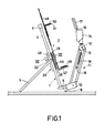
- the reading apparatus shown in Figs. 1 and 2 comprises a stand 1 carrying a work support 2.
- the stand 1 comprises two tubes 3 and 5 which function as longitudinal guides and which are preferably made of aluminium to minimize their weight. At the lower ends the tubes are interconnected by a member 5 which bears on a surface such as a table top by means of legs 6. From the member 5 the tubes 3 and 4 extend parallel to one another in an upward direction, the tubes being interconnected at their upper ends by a connecting member 7.
- a latching rod 8 extends substantially midway between the tubes 3 and 4, the ends of the rod being connected to the members 5 and 7 respectively.
- the rod 8 is chrome-plated and has a diameter which is small relative to that of the tubes 3 and 4.
- the stand 1 comprises a supporting bracket 9, which is pivotally connected to the tubes 3 and 4 which can be pivoted towards the work support 2 for easy storage of the reading apparatus.
- a U-shaped bracket 10 which carries the pivots of a parallelogram mechanism 11.
- said parallelogram mechanism comprises a substantially triangular plate 12, which on both sides carries a pin 13, which pins function as handles.
- the parallelogram mechanism 11 can be adjusted realtive to the work support.
- On the plate 12 an illuminating device 14 is arranged, which device comprises a tubular lamp 15 which extends substantially horizontally.
- the illuminating device quick-connect coupling enabling a magnifying lens 17 to be mounted and, if required, to be replaced rapidly and easily.
- the plate 12, the illuminating device 14 and the magnifying lens 17 are arranged in such a way that the lens 17 extends substantially parallel to the work support 2.
- the parallelogram mechanism 11 ensures also during its adjustment when the distance of the lens 17 relative to the work support 2 is adjusted, the lens remains in a parallel position relative to the work support 2.
- the parallelogram mechanism 11 comprises a tension spring 18 which maintains the lens setting.
- One end portion of a bolt 19 to which the spring 18 is secured limits the pivotal movement of the parallelogram mechanism 11 in the clockwise direction.
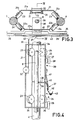
- a housing 20 is arranged,-which housing comprises walls 21 and 22 which extend parallel to the tubes 3 and 4 (see Figs. 3 and 4).
- each of the two walls comprises a side portion 21b, 21c and 22b, 22c, respectively which is bent through substantiaaly 45 0 .
- the side portions 21b and 21c are disposed so that bearings 23 on the inner sides of these side portions extend substantially in radial directions of the tubes 3 and 4.
- bearings 24 also extend in substantially radial directions of the tubes 3 and 4.
- the bearings 23 are situated inside the housing 20 and the bearings 24 are disposed outside the housing in the space between the housing and the work support 2.
- the bearings 23 and 24 are arranged pairwise at an angle of substantially 90 0 relative to each other near the tubes 3 and 4 respectively, so that both on the lower side and the upper side of the housing four bearings are present (see Fig. 4).
- This arrangement of the bearings relative to each other and the construction of the housing 20 provide a satisfactory compensation of forces and a smooth guidance during the vertical adjustment of the housing 20.
- the wall 22 carries a substantially horizontal bearing support 25, on which bearings 26 are mounted near the two ends.
- the wall 22 carries a bearing support 27 on which a bearing 28 is mounted.
- a three-point mounting for the work support 2 is obtained, the lower surface of a horizontal ledge 29 engaging with the bearings 26 and the lower surface of a ledge 30, which extends parallel to the ledge 29, engaging with the bearing 28.
- the lower bearings 26 and the upper bearing 28 together ensure that the work support 2 is guided horizontally relative to the stand 1.
- the wall 21 On the inner side the wall 21 carries a pair of projections 31 between which a roller 32 is mounted for rotation.
- a length of-steel strip 33 is coiled on the roller 32 at least partly inside the housing.
- the steel strip 33 extends from the roller 32 substantially parallel-to the latching rod 8 through a slot in an upper wall 34 of the housing towards the member 7, to which the upper end of the steel strip 33 is anchored.
- the steel strip 33 compensates for the weight of the work support
- a latching device 37 which comprises the latching rod 8 and a latching lever 38 which extends transversely of the latching rod.
- the latching lever 38 is made of a metal which is soft in comparison with the material of the rod 8.
- the latching lever 38 has a hole 39 through which the rod 8 extends, the lever extending from the rod 8 through a slot 40 in an outward direction relative to the housing 20. The lower edge of the slot 40 constitutes a fulcrum for the lever 38.
- the lever 38 is bent obliquely, downwards, a leaf spring 41 ensuring that in the retaining position the lever 38 is urged into an oblique position relative to the rod 8.
- the oblique portion of the lever 38 is connected to an elastic hook 42, the hook engaging with anactuatingrod 43, which rod is thus coupled to the hook 42 so as to be slidable in a horizontal direction.
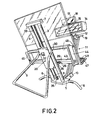
- the actating rod 43 extends to a point near the upright sides of the work support 2, where the control levers 44 and 45 are located. Relative to the upright sides of the work support said control levers are arranged in such a manner that each individual control lever can be operated without special attention.
- the control levers 44 and 45 are mounted so as to be pivotable about spindles 46, the rod 43 extending through portions of the lever which are situated at some distance from the spindle 46.
- each lever is urged away from the work support 2 via the hook 42 and the actuating rod 43. This ensures that after release of the control levers 44 and 45 the rod 43 is pivoted in the direction indicated by the arrow A, so that the latching lever occupies the oblique position relative to the rod 8 as described hereinbefore.
- the work support 2 is provided with a supporting bracket 47 which extends substantially perpendicularly relative to the major surface of the work support 2.
- this bracket is provided with elastic material with a high surface-friction.
- a part of the work support 2 which covers approximately 40 % of its height reckoned from the support bracket 47 is preferably made of a non-transparent plastics material and an upper part of the work support is made of a transparent plastics material such as perspe.
- On this upper part two magnetic strips 49 are arranged parallel to one another, the side of a bracket 50 which faces the work support being attracted against the magnetic strips.
- the side of the bracket 50 which faces the supporting bracket 47 is also provided with an elastic material 51 with a high surface-friction.
- This bracket 50 in combination with the bracket 47 serves as a flattening means for keeping pages of an open book in a flat condition.
- the bracket 47 is formed with a slot, not shown, in which the parallelogram mechanism 11 can move up to the end of the slot upon a pivotal movement towards the work support 2. This limits pivotal movements of the parallelogram mechanism 11 in an anticlockwise direction and moreover it provides a compact storage position of the parallelogram mechanism and the parts connected thereto.
- the quick-connect coupling 16 enables the rectangular lens 17 to be readily interchanged by one which provides the required degree of magnification.
- the parallelogram mechanism 11 enables the magnifying lens 17 to be adjusted as regards the distance from the work support, the lens being constantly maintained in a position parallel relative to the work support. This results in an easy adjustment of the focal distance of the loop relative to a record carrier placed on the work support, such as a book, a magazine or a newspaper. This focal distance must be adjusted in conformity with the thickness of the record carrier.
- the pages of a book are kept in a flat condition between the brackets 47 and 50, the elastic material on the brackets ensuring that the pages cannot bulge.
- the entire page area remains free, enabling the entire page to be followed unimpededly with the lens 17.
- the work support 2 is movable both in the vertical direction and in the horizontal direction. A user who is sitting on a chair with his eyes before the lens 17 can move the work support 2 to the desired position without having to move his head. Since the user is generally visually handicapped, it is important that the work support 2 can be moved as easily as possible without tiring and intricate manipulations.
- the horizontal displacement i.e. when following the lines of text, is effected very smoothly owing to the presence of the bearings 26 and 28.
- the horizontally slidable coupling between the actuating rod 43 and the hook 42 ensures that the line-height setting is maintained.
- the latching device 37 ensures that the housing 20 and the work support 2 carried by this housing cannot be lowered unintentionally, for example if the work support is subject to a shock.
- the weight-compensation means comprising the steel strip 33 ensures that a smooth movement is obtained. For this the user only has to pull one of the two control levers 44 or 45 slightly towards himself against spring force, the spring force itself being an indication to the user that the line height may change.
- the special bearing arrangement of the housing 20 on the two tubes 3 and 4 guarantees that height adjustment proceeds very gradually yet smoothly.
- the perspex upper part of the work support 2 ensures a minimal isolation of the user from his surrounding. Moreover, it is to be noted that in the swung-in condition the reading apparatus occupies a minimal space.
Landscapes
- Facsimile Scanning Arrangements (AREA)
- Tables And Desks Characterized By Structural Shape (AREA)
Abstract
Description
- The invention relates to a reading apparatus comprising a work support, which is carried by a stand and on which a record carrier such as a book or magazine can be placed, and comprising a lens which is connected to the stand and whose distance from the work support is adjustable, which work support is vertically adjustable relative to the stand, which stand comprises two upwardly directed longitudinal guides which extend parallel to one another for the vertical adjustment of the work support, a weight-compensation means being arranged between the stand and the work support and a latching device being provided, which device comprises a latching rod, which is situated between the longitudinal guides, and a latching lever which extends transversely of said rod and which is provided with a hole through which the rod extends, which lever is pivotally connected to the work support and is urged in an oblique position relative to the rod by a spring.
- A reading apparatus of this type is disclosed in United States Patent Specification 1,451,182 and serves to enable the visually handicapped to read books, newspapers, magazines etc. with the aid of a magnifying lens. For a smooth movement of the matter to be read and the lens while reading consecutive lines of text the work support of the known reading apparatus is adjustable in the vertical direction by the actuation of a stationarily arranged foot-pedal. This pedal imposes a critical sitting posture and prohibits the use of the work support on a table top. Moreover, in practice the construction of the known reading apparatus with a horizontally stationary work support generally requires a continual movement of the head of the reader.
- It is the object of the invention to provide an easy-to-operate reading apparatus of simple construction, which yields optimum results, when used by a visually handicapped person.
- To this end the invention is characterized in that the work support is also movable in a horizontal direction relative to the stand, and near the end which is remote from the latching rod the latching lever is connected to an elastic hook, which hook is coupled to an actuating rod so as to be horizontally slidable, which rod is arranged on the work support and is connected to at least one control lever situated near one of the lateral sides of the work support.
- This results in a reading apparatus which enables the text to be read to be followed easily and which does not require a continual movement of the head. When following the individual lines of text the work support is moved in a horizontal direction in such a way that the line-height setting is maintained by the horizontally slidable coupling between the actuating rod.and the elastic hook. By means of the control levers on the work support the latching device can be released for moving the support in the vertical direction, allowing the hand to remain at the same place on the support both during the height adjustment and the horizontal adjustment of the support. Thus, the reading apparatus in accordance with the invention is easy to operate during reading and can be placed on, for example, a table top.
- A preferred embodiment of the invention is characterized in that two control levers are situated on the work support, which control levers near an upright side of the work support are each pivotally connected thereto, the actuating rod extending between the control levers in a horizontal direction. These steps result in a convenient operation and, consequently, a smooth adjustment of the work support by means of the two conveniently arranged. control levers.
- A further preferred embodiment of the invention is characterized in that the latching lever is situated at least partly in a housing which is connected to the work support and which is disposed between the two longitudinal guides, a wall of said housing being provided with slot whose lower edge constitutes a pivot for the latching lever. This yields a simple and cheap but adequately shielded construction.
- Another preferred embodiment of the invention is characterized in that the weight-compensation means comprise a length of strip steel which is coiled at least partly inside the housing, the non-coiled portion between the housing and the stand being situated near the latching rod between the longitudinal guides. This results in a compact arrangement of the weight-comprensation means, which is practically invisible from the front of the reading apparatus.
- Still another preferred embodiment of the invention is characterized in that for the vertical guidance of the work support the housing carries a plurality of bearings which are arranged in pairs below and above the latching lever and which co-operate with the longitudinal guides during the vertical adjustment of the work support. In this way a smooth height adjustment of the work support is obtained.
- Finally, another preferred embodiment of the invention, which is provided with an illuminating device whose distance from the work support is adjusable, is characterized in that the illuminating device is adjustably connected to the lower surface of the stand by means of a pivotable parallelogram mechanism and the magnifying lens is connected to the upper side of the illuminating device. The parallelogram mechanism ensures that the parallel position of the work support and the lens is maintained without obstrucing the field of view.
- An embodiment of the invention will now be described in more detail, by way of example, with reference to the drawings. In the drawings:
- Fig. 1 is a side view of a reading apparatus in accordance with the invention;
- Fig. 2 is a perspective rear view of the reading apparatus shown in Fig. 1;
- Fig. 3 is a cross-sectional view, on an enlarged scale, taken on the lines III-III in Fig. 1;
- Fig. 4 is a cross-sectional view taken on the lines IV-IV in Fig. 3.
- ' The reading apparatus shown in Figs. 1 and 2 comprises a stand 1 carrying a
work support 2. For this purpose the stand 1 comprises twotubes member 5 which bears on a surface such as a table top by means oflegs 6. From themember 5 thetubes 3 and 4 extend parallel to one another in an upward direction, the tubes being interconnected at their upper ends by a connecting member 7. Alatching rod 8 extends substantially midway between thetubes 3 and 4, the ends of the rod being connected to themembers 5 and 7 respectively. Preferably , therod 8 is chrome-plated and has a diameter which is small relative to that of thetubes 3 and 4. Further, the stand 1 comprises a supportingbracket 9, which is pivotally connected to thetubes 3 and 4 which can be pivoted towards thework support 2 for easy storage of the reading apparatus. - At the front side of the member 5 a
U-shaped bracket 10 is arranged which carries the pivots of aparallelogram mechanism 11. At the side which is remote from thebracket 10 said parallelogram mechanism comprises a substantiallytriangular plate 12, which on both sides carries apin 13, which pins function as handles. In this way theparallelogram mechanism 11 can be adjusted realtive to the work support. On theplate 12 anilluminating device 14 is arranged, which device comprises atubular lamp 15 which extends substantially horizontally. At the upper side the illuminating device quick-connect coupling enabling amagnifying lens 17 to be mounted and, if required, to be replaced rapidly and easily. Preferably, theplate 12, theilluminating device 14 and themagnifying lens 17 are arranged in such a way that thelens 17 extends substantially parallel to thework support 2. Theparallelogram mechanism 11 ensures also during its adjustment when the distance of thelens 17 relative to thework support 2 is adjusted, the lens remains in a parallel position relative to the work support 2.For this purpose theparallelogram mechanism 11 comprises atension spring 18 which maintains the lens setting. One end portion of abolt 19 to which thespring 18 is secured limits the pivotal movement of theparallelogram mechanism 11 in the clockwise direction. - Between the
tubes 3 and 4 ahousing 20 is arranged,-which housing compriseswalls tubes 3 and 4 (see Figs. 3 and 4). On both sides if their major portions each of the two walls comprises aside portion substantiaaly 450. As shown in Fig. 3 theside portions bearings 23 on the inner sides of these side portions extend substantially in radial directions of thetubes 3 and 4. On the outer sides of theside portions 22c bearings 24 also extend in substantially radial directions of thetubes 3 and 4. Thus, thebearings 23 are situated inside thehousing 20 and thebearings 24 are disposed outside the housing in the space between the housing and thework support 2. Thebearings tubes 3 and 4 respectively, so that both on the lower side and the upper side of the housing four bearings are present (see Fig. 4). This arrangement of the bearings relative to each other and the construction of thehousing 20 provide a satisfactory compensation of forces and a smooth guidance during the vertical adjustment of thehousing 20. - Near the lower side the
wall 22 carries a substantiallyhorizontal bearing support 25, on whichbearings 26 are mounted near the two ends. Near the upper side thewall 22 carries abearing support 27 on which abearing 28 is mounted. In this way a three-point mounting for thework support 2 is obtained, the lower surface of ahorizontal ledge 29 engaging with thebearings 26 and the lower surface of aledge 30, which extends parallel to theledge 29, engaging with thebearing 28. Thelower bearings 26 and the upper bearing 28 together ensure that thework support 2 is guided horizontally relative to the stand 1. On the inner side thewall 21 carries a pair ofprojections 31 between which aroller 32 is mounted for rotation. A length of-steel strip 33 is coiled on theroller 32 at least partly inside the housing. Thesteel strip 33 extends from theroller 32 substantially parallel-to thelatching rod 8 through a slot in anupper wall 34 of the housing towards the member 7, to which the upper end of thesteel strip 33 is anchored. Thesteel strip 33 compensates for the weight of thework support 2. - On the
latching rod 8 near themember 5 an elastic, preferably rubber,buffer 35 is arranged, which buffer limits the downward travel of thehousing 20 by abutment against alower wall 36 of the housing. For retaining thehousing 20 and thework support 2 carried by said housing after vertical adjustment there is provided alatching device 37, which comprises thelatching rod 8 and alatching lever 38 which extends transversely of the latching rod. Preferably, thelatching lever 38 is made of a metal which is soft in comparison with the material of therod 8. Thelatching lever 38 has ahole 39 through which therod 8 extends, the lever extending from therod 8 through aslot 40 in an outward direction relative to thehousing 20. The lower edge of theslot 40 constitutes a fulcrum for thelever 38. Outside thehousing 20 thelever 38 is bent obliquely, downwards, aleaf spring 41 ensuring that in the retaining position thelever 38 is urged into an oblique position relative to therod 8. The oblique portion of thelever 38 is connected to anelastic hook 42, the hook engaging withanactuatingrod 43, which rod is thus coupled to thehook 42 so as to be slidable in a horizontal direction. As is shown in Fig. 2, theactating rod 43 extends to a point near the upright sides of thework support 2, where the control levers 44 and 45 are located. Relative to the upright sides of the work support said control levers are arranged in such a manner that each individual control lever can be operated without special attention. The control levers 44 and 45 are mounted so as to be pivotable aboutspindles 46, therod 43 extending through portions of the lever which are situated at some distance from thespindle 46. By means of. theleaf spring 41 each lever is urged away from thework support 2 via thehook 42 and theactuating rod 43. This ensures that after release of the control levers 44 and 45 therod 43 is pivoted in the direction indicated by the arrow A, so that the latching lever occupies the oblique position relative to therod 8 as described hereinbefore. However, if the ends of the control levers 44 and/or 45 are moved towards thework support 2, therod 43 is pivoted against spring force in a direction opposite to that indicated by the arrow A, so that inside thehousing 20 the latchinglever 38 occupies a substantially perpendicular position relative to therod 8. As a result of this unlatching is effected, because the diameter of thehole 39 is slightly greater than the outer diameter of therod 8, which enables thehousing 20 and consequently thework support 2 connected thereto, to be positioned in an easy manner. - Near the lower edge the
work support 2 is provided with a supportingbracket 47 which extends substantially perpendicularly relative to the major surface of thework support 2. Preferably this bracket is provided with elastic material with a high surface-friction. A part of thework support 2 which covers approximately 40 % of its height reckoned from thesupport bracket 47 is preferably made of a non-transparent plastics material and an upper part of the work support is made of a transparent plastics material such as perspe. On this upper part twomagnetic strips 49 are arranged parallel to one another, the side of abracket 50 which faces the work support being attracted against the magnetic strips. The side of thebracket 50 which faces the supportingbracket 47 is also provided with anelastic material 51 with a high surface-friction. Thisbracket 50 in combination with thebracket 47 serves as a flattening means for keeping pages of an open book in a flat condition. For the description of such a flattening device reference is made to the Applicant's non-prepublished Netherlands Patent Application no. 8200327 filed on 29 January 1982. Thebracket 47 is formed with a slot, not shown, in which theparallelogram mechanism 11 can move up to the end of the slot upon a pivotal movement towards thework support 2. This limits pivotal movements of theparallelogram mechanism 11 in an anticlockwise direction and moreover it provides a compact storage position of the parallelogram mechanism and the parts connected thereto. - After the
stand 9 has been swung out the reading apparatus is placed on a surface such as a table top, desk or bed. The quick-connect coupling 16 enables therectangular lens 17 to be readily interchanged by one which provides the required degree of magnification. Theparallelogram mechanism 11 enables the magnifyinglens 17 to be adjusted as regards the distance from the work support, the lens being constantly maintained in a position parallel relative to the work support. This results in an easy adjustment of the focal distance of the loop relative to a record carrier placed on the work support, such as a book, a magazine or a newspaper. This focal distance must be adjusted in conformity with the thickness of the record carrier. The pages of a book are kept in a flat condition between thebrackets lens 17. As thework support 2 is movable both in the vertical direction and in the horizontal direction. A user who is sitting on a chair with his eyes before thelens 17 can move thework support 2 to the desired position without having to move his head. Since the user is generally visually handicapped, it is important that thework support 2 can be moved as easily as possible without tiring and intricate manipulations. The horizontal displacement, i.e. when following the lines of text, is effected very smoothly owing to the presence of thebearings rod 43 and thehook 42 ensures that the line-height setting is maintained. The latchingdevice 37 ensures that thehousing 20 and thework support 2 carried by this housing cannot be lowered unintentionally, for example if the work support is subject to a shock. When adjusting the line-height of the book or the like present on the work support the weight-compensation means comprising thesteel strip 33 ensures that a smooth movement is obtained. For this the user only has to pull one of the twocontrol levers housing 20 on the twotubes 3 and 4 guarantees that height adjustment proceeds very gradually yet smoothly. When the correct line-height is reached thelever levers - It is to be noted that the perspex upper part of the
work support 2 ensures a minimal isolation of the user from his surrounding. Moreover, it is to be noted that in the swung-in condition the reading apparatus occupies a minimal space.
Claims (7)
Applications Claiming Priority (2)
| Application Number | Priority Date | Filing Date | Title |
|---|---|---|---|
| NL8203552 | 1982-09-13 | ||
| NL8203552A NL8203552A (en) | 1982-09-13 | 1982-09-13 | READING LESSON. |
Publications (2)
| Publication Number | Publication Date |
|---|---|
| EP0103341A1 true EP0103341A1 (en) | 1984-03-21 |
| EP0103341B1 EP0103341B1 (en) | 1986-05-07 |
Family
ID=19840264
Family Applications (1)
| Application Number | Title | Priority Date | Filing Date |
|---|---|---|---|
| EP19830201305 Expired EP0103341B1 (en) | 1982-09-13 | 1983-09-12 | Reading apparatus |
Country Status (3)
| Country | Link |
|---|---|
| EP (1) | EP0103341B1 (en) |
| DE (1) | DE3363412D1 (en) |
| NL (1) | NL8203552A (en) |
Cited By (1)
| Publication number | Priority date | Publication date | Assignee | Title |
|---|---|---|---|---|
| CN112932067A (en) * | 2021-02-07 | 2021-06-11 | 深圳腾盛云科技有限公司 | Tensile teaching podium of intelligence |
Citations (3)
| Publication number | Priority date | Publication date | Assignee | Title |
|---|---|---|---|---|
| DE143193C (en) * | ||||
| GB191402330A (en) * | 1912-12-30 | 1914-06-04 | Ignacz Kaufmann | An Improved Apparatus for Facilitating Reading. |
| US1451182A (en) * | 1921-04-08 | 1923-04-10 | Robert M Searle | Reading appliance |
-
1982
- 1982-09-13 NL NL8203552A patent/NL8203552A/en not_active Application Discontinuation
-
1983
- 1983-09-12 EP EP19830201305 patent/EP0103341B1/en not_active Expired
- 1983-09-12 DE DE8383201305T patent/DE3363412D1/en not_active Expired
Patent Citations (3)
| Publication number | Priority date | Publication date | Assignee | Title |
|---|---|---|---|---|
| DE143193C (en) * | ||||
| GB191402330A (en) * | 1912-12-30 | 1914-06-04 | Ignacz Kaufmann | An Improved Apparatus for Facilitating Reading. |
| US1451182A (en) * | 1921-04-08 | 1923-04-10 | Robert M Searle | Reading appliance |
Cited By (1)
| Publication number | Priority date | Publication date | Assignee | Title |
|---|---|---|---|---|
| CN112932067A (en) * | 2021-02-07 | 2021-06-11 | 深圳腾盛云科技有限公司 | Tensile teaching podium of intelligence |
Also Published As
| Publication number | Publication date |
|---|---|
| NL8203552A (en) | 1984-04-02 |
| EP0103341B1 (en) | 1986-05-07 |
| DE3363412D1 (en) | 1986-06-12 |
Similar Documents
| Publication | Publication Date | Title |
|---|---|---|
| US4893775A (en) | Copy holder stand | |
| US5433415A (en) | Adjustable book holder | |
| US4240663A (en) | Adjustable stacking chair | |
| US4275863A (en) | Bock holder | |
| US5221070A (en) | Adjustable book holder | |
| US5052650A (en) | Copyholder | |
| US7541533B2 (en) | Apparatus having page turning capability for reading assistance | |
| US5373772A (en) | Page turner | |
| KR20000016844A (en) | A sheet stand | |
| EP0032305B1 (en) | A document cover supporting mechanism for a copying apparatus | |
| EP0103341B1 (en) | Reading apparatus | |
| US4882969A (en) | Page turning device | |
| US4172660A (en) | Copying apparatus cover | |
| US5458312A (en) | Inverted book holder | |
| US5259581A (en) | Inverted book holding and page turning device | |
| US4472897A (en) | Universally adjustable paper holder apparatus | |
| US20010023916A1 (en) | Book display method and apparatus | |
| US2741869A (en) | Reading stand | |
| US4327889A (en) | Reading-apparatus | |
| US5067682A (en) | Book holder | |
| CA1310243C (en) | Copyholder | |
| US5489079A (en) | Side facing book holding and page turning device | |
| US4329799A (en) | Typing copy stand | |
| US5275306A (en) | Literature dispensing mechanism | |
| US4054373A (en) | Microform viewer |
Legal Events
| Date | Code | Title | Description |
|---|---|---|---|
| PUAI | Public reference made under article 153(3) epc to a published international application that has entered the european phase |
Free format text: ORIGINAL CODE: 0009012 |
|
| AK | Designated contracting states |
Designated state(s): BE DE FR GB NL |
|
| 17P | Request for examination filed |
Effective date: 19840705 |
|
| GRAA | (expected) grant |
Free format text: ORIGINAL CODE: 0009210 |
|
| AK | Designated contracting states |
Kind code of ref document: B1 Designated state(s): BE DE FR GB NL |
|
| REF | Corresponds to: |
Ref document number: 3363412 Country of ref document: DE Date of ref document: 19860612 |
|
| ET | Fr: translation filed | ||
| PLBE | No opposition filed within time limit |
Free format text: ORIGINAL CODE: 0009261 |
|
| STAA | Information on the status of an ep patent application or granted ep patent |
Free format text: STATUS: NO OPPOSITION FILED WITHIN TIME LIMIT |
|
| 26N | No opposition filed | ||
| PGFP | Annual fee paid to national office [announced via postgrant information from national office to epo] |
Ref country code: NL Payment date: 19870930 Year of fee payment: 5 |
|
| PG25 | Lapsed in a contracting state [announced via postgrant information from national office to epo] |
Ref country code: GB Effective date: 19880912 |
|
| PG25 | Lapsed in a contracting state [announced via postgrant information from national office to epo] |
Ref country code: BE Effective date: 19880930 |
|
| BERE | Be: lapsed |
Owner name: TECHNISCHE HOGESCHOOL EINDHOVEN Effective date: 19880930 |
|
| PG25 | Lapsed in a contracting state [announced via postgrant information from national office to epo] |
Ref country code: NL Effective date: 19890401 |
|
| REG | Reference to a national code |
Ref country code: GB Ref legal event code: PCNP |
|
| NLV4 | Nl: lapsed or anulled due to non-payment of the annual fee | ||
| PG25 | Lapsed in a contracting state [announced via postgrant information from national office to epo] |
Ref country code: FR Free format text: LAPSE BECAUSE OF NON-PAYMENT OF DUE FEES Effective date: 19890531 |
|
| GBPC | Gb: european patent ceased through non-payment of renewal fee | ||
| PG25 | Lapsed in a contracting state [announced via postgrant information from national office to epo] |
Ref country code: DE Effective date: 19890601 |
|
| REG | Reference to a national code |
Ref country code: FR Ref legal event code: ST |